Surveillance Robot Design and Implementation
VerifiedAdded on 2020/03/23
|13
|2827
|258
AI Summary
This assignment details the design and implementation of a cost-effective surveillance robot controlled via a mobile phone. The robot features an automatic answering mode for incoming calls and utilizes key inputs (2, 4, 6, 8) on the controller for movement (forward, left turn, right turn, backward). A separate radio frequency controller manages the robotic arm and camera. The document explores potential future upgrades like bomb disposal capabilities, live video streaming, weight reduction, night vision, stair climbing, and solar recharging.
Contribute Materials
Your contribution can guide someone’s learning journey. Share your
documents today.
PROJECT DESIGN
ABSTRACT: Disasters, natural or man-made are very difficult to predict. Man-made
disasters can be prevented to a certain level, but if disaster strikes, an effective post disaster
management is necessary which includes immediate searching and rescuing of trapped,
unfortunate human beings and animals. Sometimes human beings, themselves cannot engage
directly in such hazardous/ unstable regions for search and rescue operations, which puts their
lives in danger too. Therefore, we make use of Robots which should be both fast and
powerful.
This robot is designed for search and rescue in the roughest terrains, which are in accessible
to other ordinary robots. It is built for power and speed. It is an omnidirectional differentially
driven tracked vehicle powered by 4DC geared motors (Ghangrekar, 2009) of 45rpm speed
and delivering a torque of 3kgf-cm each. It is remote controlled by two 433MHz ASK
Transmitter/Receiver, which together provided 8 coded channels (Schöner, 2015). It has a
range of about 120 metres. A wireless camera set is mounted on the robot which transmits
live video & audio to a receiver which is connected to a desktop/laptop via USB TV tuner
(Yuh, 2012). This captured video /image can be used for surveillance and /or image
processing.
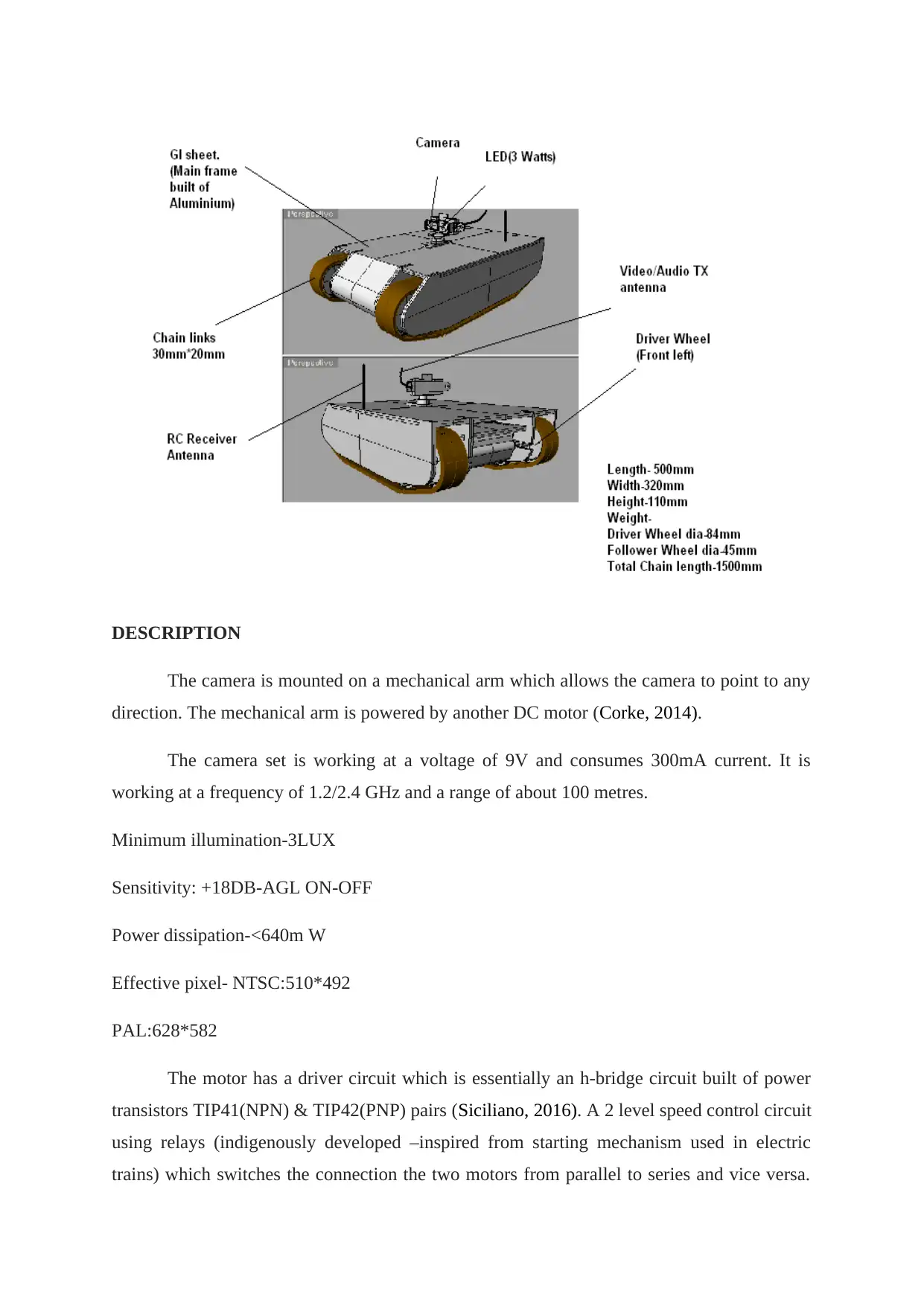
DESIGN (Perspective)
Secure Best Marks with AI Grader
Need help grading? Try our AI Grader for instant feedback on your assignments.
DESCRIPTION
The camera is mounted on a mechanical arm which allows the camera to point to any
direction. The mechanical arm is powered by another DC motor (Corke, 2014).
The camera set is working at a voltage of 9V and consumes 300mA current. It is
working at a frequency of 1.2/2.4 GHz and a range of about 100 metres.
Minimum illumination-3LUX
Sensitivity: +18DB-AGL ON-OFF
Power dissipation-<640m W
Effective pixel- NTSC:510*492
PAL:628*582
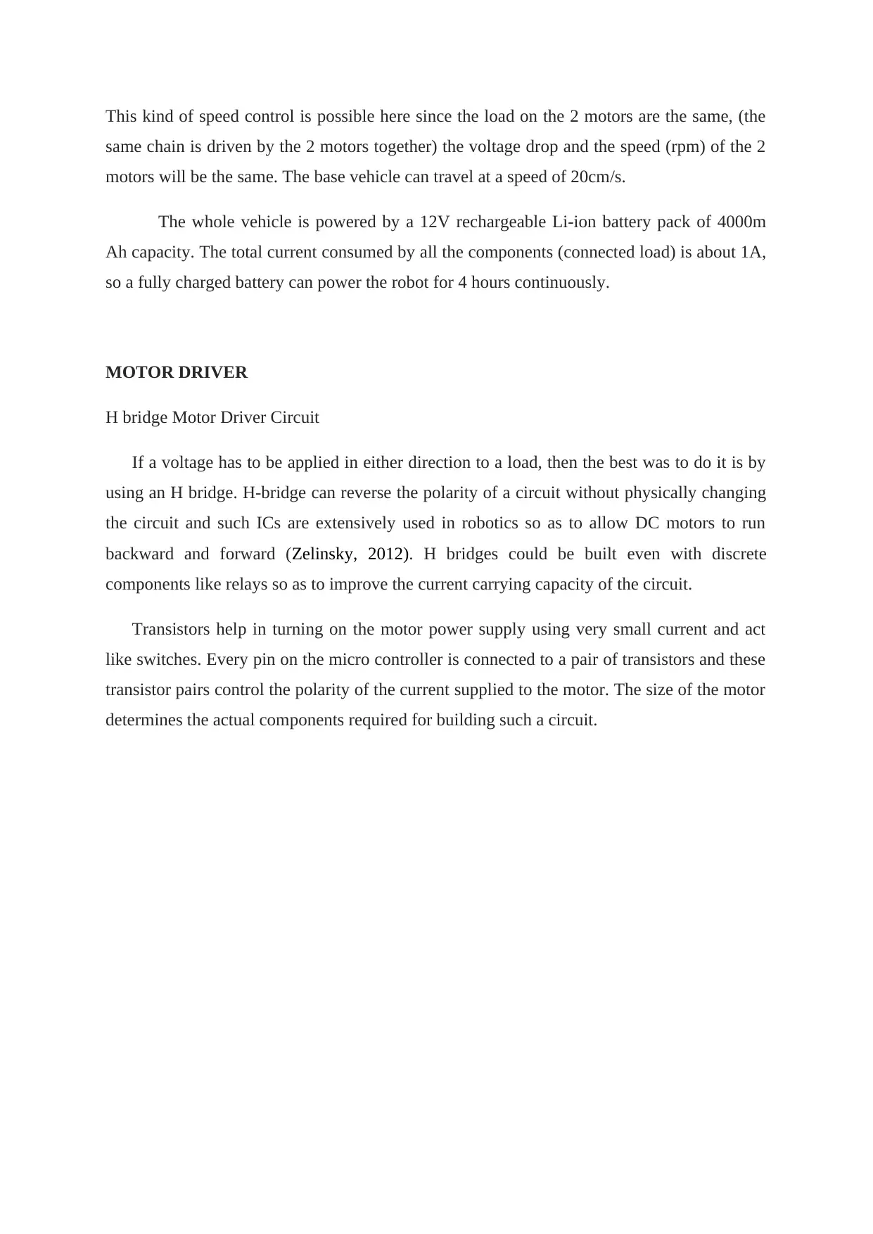
The motor has a driver circuit which is essentially an h-bridge circuit built of power
transistors TIP41(NPN) & TIP42(PNP) pairs (Siciliano, 2016). A 2 level speed control circuit
using relays (indigenously developed –inspired from starting mechanism used in electric
trains) which switches the connection the two motors from parallel to series and vice versa.
This kind of speed control is possible here since the load on the 2 motors are the same, (the
same chain is driven by the 2 motors together) the voltage drop and the speed (rpm) of the 2
motors will be the same. The base vehicle can travel at a speed of 20cm/s.
The whole vehicle is powered by a 12V rechargeable Li-ion battery pack of 4000m
Ah capacity. The total current consumed by all the components (connected load) is about 1A,
so a fully charged battery can power the robot for 4 hours continuously.
MOTOR DRIVER
H bridge Motor Driver Circuit
If a voltage has to be applied in either direction to a load, then the best was to do it is by
using an H bridge. H-bridge can reverse the polarity of a circuit without physically changing
the circuit and such ICs are extensively used in robotics so as to allow DC motors to run
backward and forward (Zelinsky, 2012). H bridges could be built even with discrete
components like relays so as to improve the current carrying capacity of the circuit.
Transistors help in turning on the motor power supply using very small current and act
like switches. Every pin on the micro controller is connected to a pair of transistors and these
transistor pairs control the polarity of the current supplied to the motor. The size of the motor
determines the actual components required for building such a circuit.
MOTOR SPECIFICATION
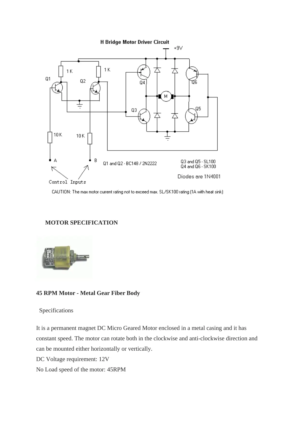
45 RPM Motor - Metal Gear Fiber Body
Specifications
It is a permanent magnet DC Micro Geared Motor enclosed in a metal casing and it has
constant speed. The motor can rotate both in the clockwise and anti-clockwise direction and
can be mounted either horizontally or vertically.
DC Voltage requirement: 12V
No Load speed of the motor: 45RPM
Secure Best Marks with AI Grader
Need help grading? Try our AI Grader for instant feedback on your assignments.
Torque generated by the motor: 3Kg-cm
No load current requirement of the motor: 0.03A
Locked rotor current: >=0.17A
STARTING AND SPEED CONTROL OF MOTORS
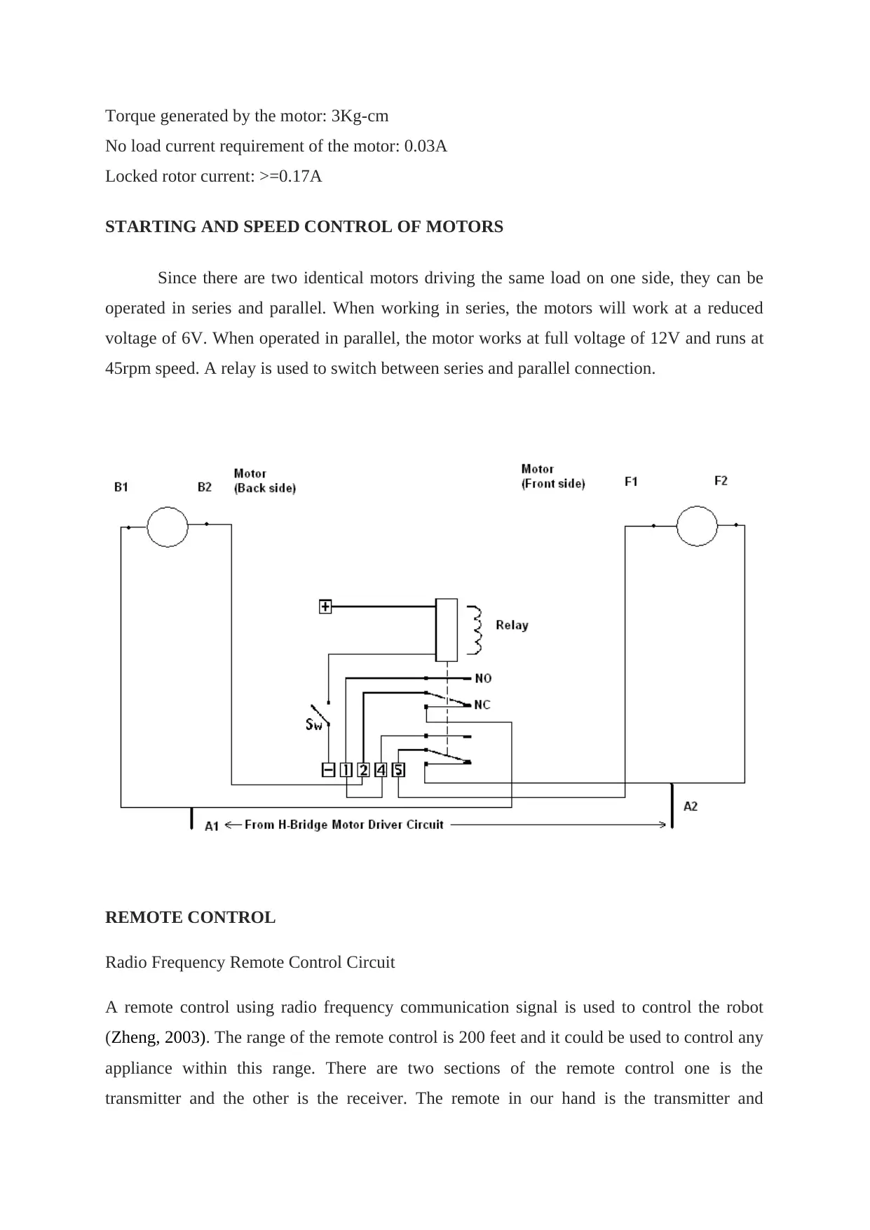
Since there are two identical motors driving the same load on one side, they can be
operated in series and parallel. When working in series, the motors will work at a reduced
voltage of 6V. When operated in parallel, the motor works at full voltage of 12V and runs at
45rpm speed. A relay is used to switch between series and parallel connection.
REMOTE CONTROL
Radio Frequency Remote Control Circuit
A remote control using radio frequency communication signal is used to control the robot
(Zheng, 2003). The range of the remote control is 200 feet and it could be used to control any
appliance within this range. There are two sections of the remote control one is the
transmitter and the other is the receiver. The remote in our hand is the transmitter and
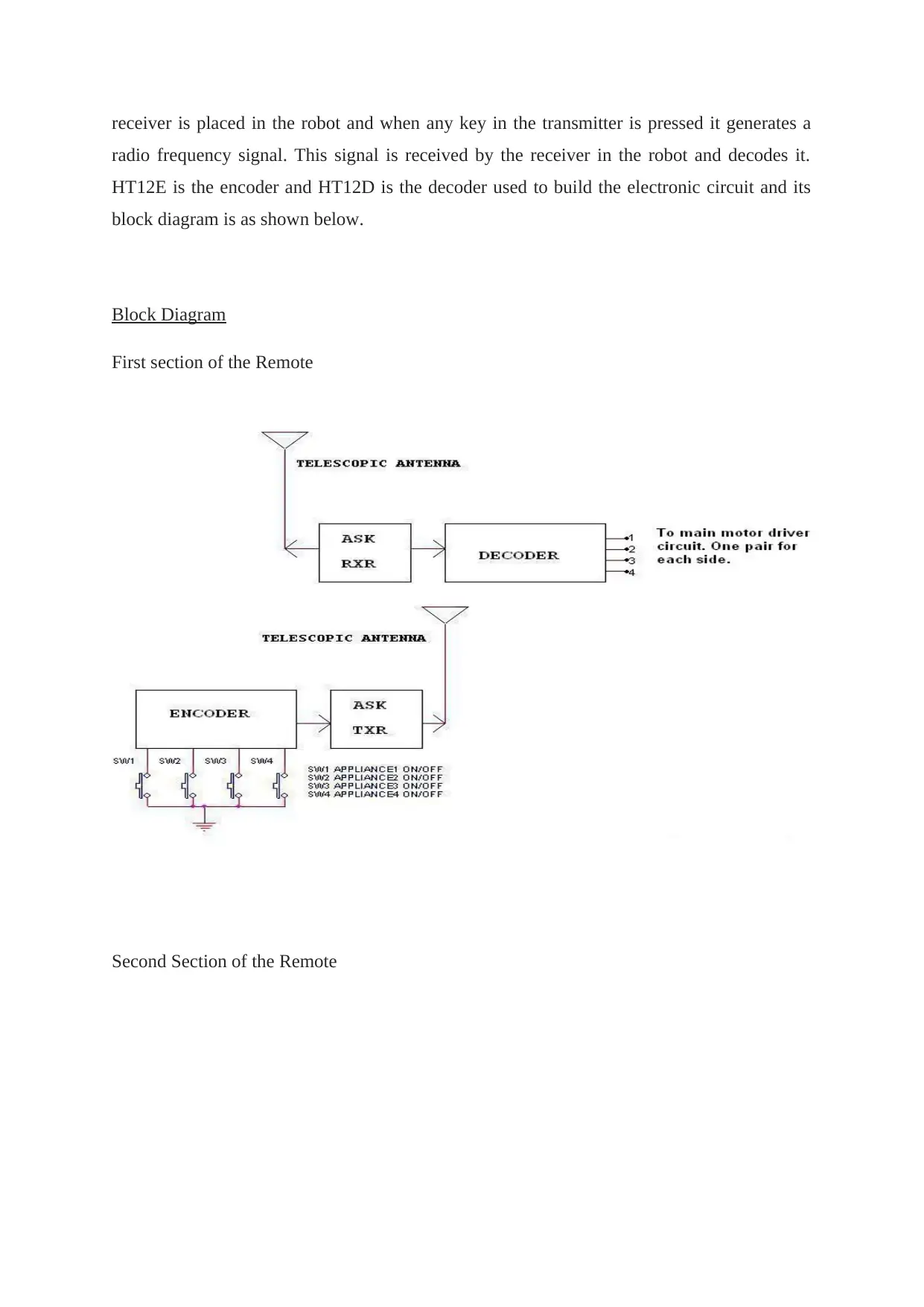
receiver is placed in the robot and when any key in the transmitter is pressed it generates a
radio frequency signal. This signal is received by the receiver in the robot and decodes it.
HT12E is the encoder and HT12D is the decoder used to build the electronic circuit and its
block diagram is as shown below.
Block Diagram
First section of the Remote
Second Section of the Remote
radio frequency signal. This signal is received by the receiver in the robot and decodes it.
HT12E is the encoder and HT12D is the decoder used to build the electronic circuit and its
block diagram is as shown below.
Block Diagram
First section of the Remote
Second Section of the Remote
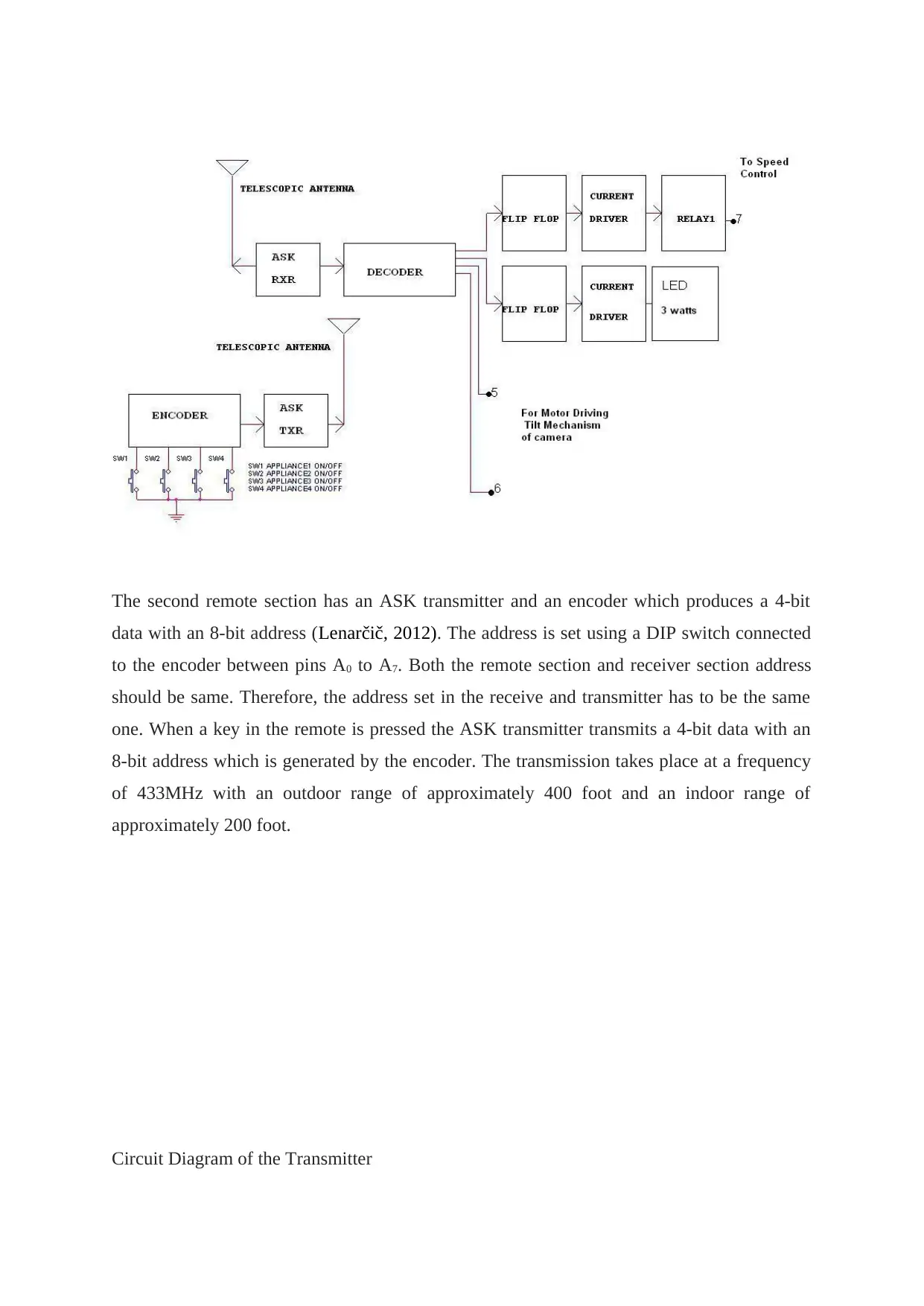
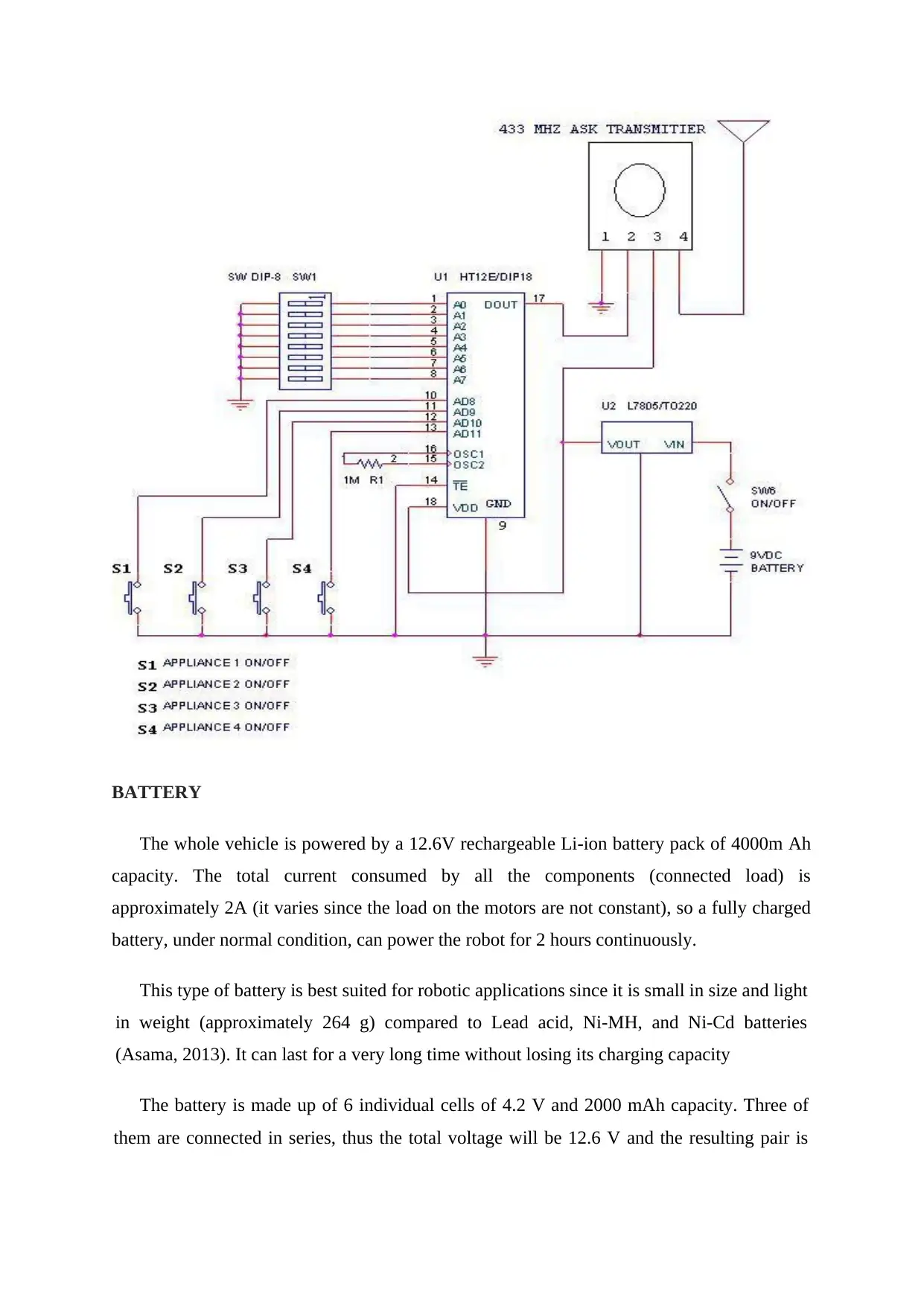
The second remote section has an ASK transmitter and an encoder which produces a 4-bit
data with an 8-bit address (Lenarčič, 2012). The address is set using a DIP switch connected
to the encoder between pins A0 to A7. Both the remote section and receiver section address
should be same. Therefore, the address set in the receive and transmitter has to be the same
one. When a key in the remote is pressed the ASK transmitter transmits a 4-bit data with an
8-bit address which is generated by the encoder. The transmission takes place at a frequency
of 433MHz with an outdoor range of approximately 400 foot and an indoor range of
approximately 200 foot.
Circuit Diagram of the Transmitter
Paraphrase This Document
Need a fresh take? Get an instant paraphrase of this document with our AI Paraphraser
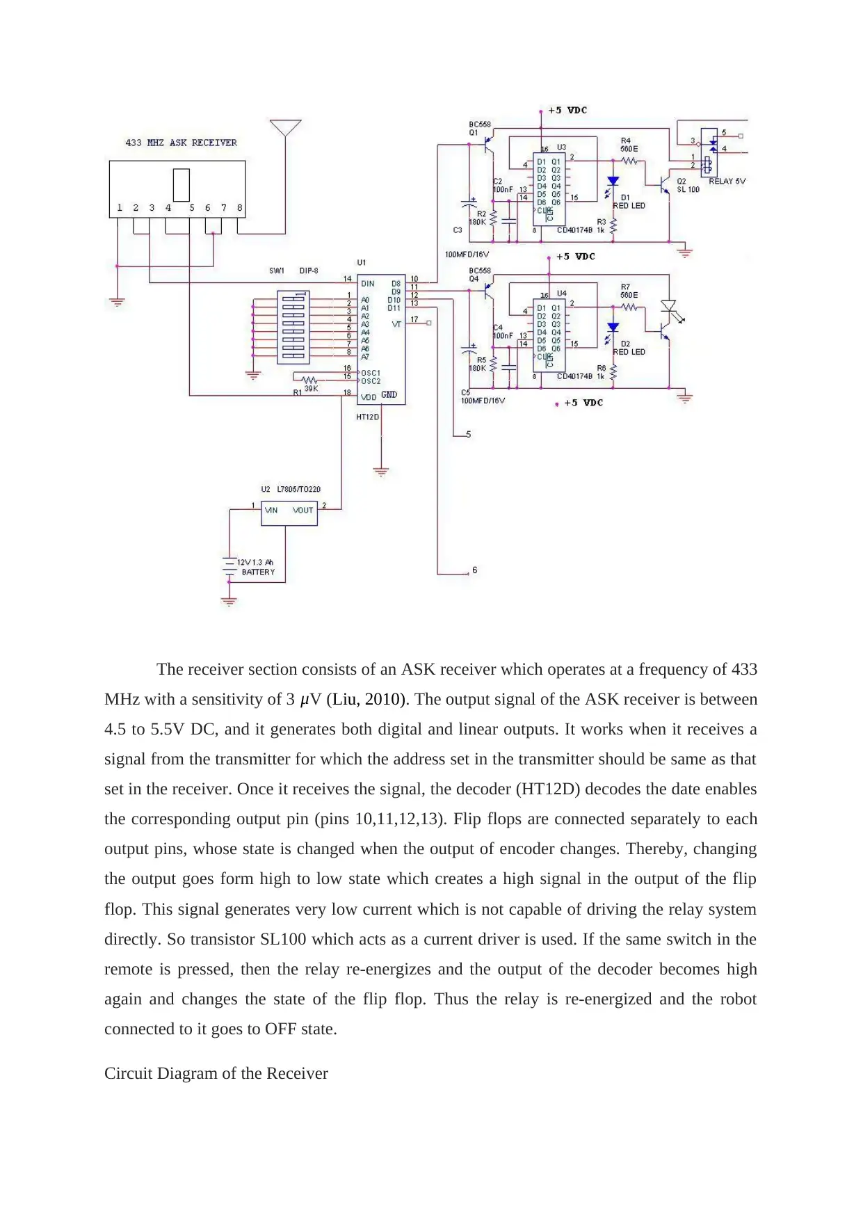
The receiver section consists of an ASK receiver which operates at a frequency of 433
MHz with a sensitivity of 3 μV (Liu, 2010). The output signal of the ASK receiver is between
4.5 to 5.5V DC, and it generates both digital and linear outputs. It works when it receives a
signal from the transmitter for which the address set in the transmitter should be same as that
set in the receiver. Once it receives the signal, the decoder (HT12D) decodes the date enables
the corresponding output pin (pins 10,11,12,13). Flip flops are connected separately to each
output pins, whose state is changed when the output of encoder changes. Thereby, changing
the output goes form high to low state which creates a high signal in the output of the flip
flop. This signal generates very low current which is not capable of driving the relay system
directly. So transistor SL100 which acts as a current driver is used. If the same switch in the
remote is pressed, then the relay re-energizes and the output of the decoder becomes high
again and changes the state of the flip flop. Thus the relay is re-energized and the robot
connected to it goes to OFF state.
Circuit Diagram of the Receiver
BATTERY
The whole vehicle is powered by a 12.6V rechargeable Li-ion battery pack of 4000m Ah
capacity. The total current consumed by all the components (connected load) is
approximately 2A (it varies since the load on the motors are not constant), so a fully charged
battery, under normal condition, can power the robot for 2 hours continuously.
This type of battery is best suited for robotic applications since it is small in size and light
in weight (approximately 264 g) compared to Lead acid, Ni-MH, and Ni-Cd batteries
(Asama, 2013). It can last for a very long time without losing its charging capacity
The battery is made up of 6 individual cells of 4.2 V and 2000 mAh capacity. Three of
them are connected in series, thus the total voltage will be 12.6 V and the resulting pair is
connected in parallel thus the charge capacity is doubled to 4000mAh and the max discharge
current is also doubled to 4 Amps.
BATTERY CHARGER
The charger provides maximum protection for the Li-Ion / Li-Po batteries. When a
traditional charger only charges the battery pack in series without detecting the defective cell
in the battery pack a charger that charges the cells individually is used. Thereby, ensuring a
long battery life and perfect charging of each cell it also has indication for power and charge.
The input for the battery is 12 V DC, which has to be provided separately through a power
supply.
CHASSIS
The chassis is completely built using PVC rectangular channels (casing and capping). It is
very easy to work on this material but the disadvantage is that it is not very strong. All the
members are fastened using nuts and bolts.
APPLICATIONS
In military (Roberts, 2006), to spy on enemies and to watch their movements (should
be equipped with IR cameras for night vision), to detect mine fields, trenches etc.
In industries, as mobile surveillance systems
In shops and showrooms for security
To monitor a burnt, unstable building from the inside
Can even be used for night patrolling
Can be fitted with a robotic arm for picking up objects, which will be used for bomb
disposals.
Videography and photography in dangerous environments such as in the wild or near
a volcano.
In commando operations; to negotiate with terrorists; can carry weapons which are
small and automatic, but then its mission changes from search & rescue to search &
destroy (Pratihar, 2010).
REFLECTION
Secure Best Marks with AI Grader
Need help grading? Try our AI Grader for instant feedback on your assignments.
As can been seen from the design part the robot is controlled using radio frequency
controllers and during the designing stage it was decided to mount the camera on a robotic
arm so that the camera angle could be changed as per requirement. But all the four channels
in the initial radio frequency controller were used up by the four motors mounted to rotate the
wheel. Therefore, it was decided to add another radio frequency controller for controlling the
robotic arm on which the camera is to be mounted.
The radio frequency controller had two more channels remaining since only two channels
were required by the robotic arm one channel for clockwise rotation of the motor used in the
arm and the other for anticlockwise rotation. The other two channels in the radio frequency
controller were used to control the camera on-off. Now the intent was to use two radio
frequency controllers but the problem was that when one controller is operating the other
controller ceases to operate. This problem is due to the radio controller itself because radio
frequency is the band which has the highest level of noise in it and is therefore susceptible to
heavy interference and that is why only one is operating at a time because the one that is
operating blocks the signal from the other from reaching the receiver.
The problem had to be solved and for this a signal which is not susceptible to noise was
required to be transmitted and it was decided to control the robot using DTMF (dual tone
multiple frequency) signals (Dasch, 2013). DTMF signal is the signal which produces the
beep sound when one of the keys in a cell phone is pressed in between a call. Each key
produces a unique tone which is actually the combination of two signals of different
frequencies and since it is a combination of two different frequencies it is not affected by
surrounding noises which comprise of signals of singular frequency. Now the problem was
how to implement the controls which uses such a signal.
The answer was to use a DTMF decoder which can decode the DTMF signal. Now for
controlling the vehicle using a DTMF decoder a receiver and transmitter was required and
two mobile phones were used as the receiver and transmitter (Cox, 2012). The receiver
mobile phone was attached to the DTMF decoder and it was set it automatic answering mode
so that when you make a call to the receiver mobile phone it answers it automatically thereby
avoiding the human interface (National Research Council, 2003). The transmitting mobile
phone acts as the controller and keys 2, 4, 6 and 8 were used to control the robot. 2 is for
forward movement, 4 for turning left, 6 for turning right and 8 for backward movement
(Koskinen, 2014). The radio frequency controller was used to control the robotic arm and the
camera only in which case it worked without any interference.
PROFESSIONAL PRACTICE / FUTURE WORK
Various types of improvements could be brought out in the design like connecting a robotic
for bomb disposal, a tab with internet connection could be connected to broadcast live videos,
the weight of the robot could be brought down by replacing the chassis with aluminum. The
camera could be replaced using night vision IR cameras, the robot could be designed to climb
stairs and the camera could be controlled more precisely using servomotors. The charger used
to recharge the battery could be replaced by an inbuilt solar recharging system thereby,
making the robot sustainable and giving it increased working hours.
CONCLUSION
This is a highly economic surveillance robot with simple and worldwide control
range. Its design could be easily manufactured as all parts are locally available and requires
less maintenance. Above all it is a multipurpose robot; it can be used for military operations
by upgrading it with stealth mechanisms, small automatic weapons, GPS etc. But at the same
time it can be readily used for home security purpose and controls are simple also any mobile
phone can be used for controlling the robot.
REFERENCES
Asama, H.T. F. (2013). Distributed Autonomous Robotic Systems 2. Spain: Springer.
Corke, P.I. (2014). Experimental Robotics VI. New York: Springer.
Cox, I.J. (2012). Autonomous Robot Vehicles. New York: Springer.
Dasch, J.M. (2013). The TARDEC Story: Sixty-five Years of Innovation 1946-2010. London:
Government Printing Office.
Ghangrekar, S. Y. (2009). A Path Planning and Obstacle Avoidance Algorithm for an
Autonomous Robotic Vehicle. China: University of North Carolina at Charlotte.
Koskinen, K.A.H. (2014). Intelligent Autonomous Vehicles 1995. London: Elsevier.
Liu, H.D.G. (2010). Robot Intelligence: An Advanced Knowledge Processing Approach.
London: Springer.
Lenarčič, J.V. P. (2012). Recent Advances in Robot Kinematics. Spain: Springer.
National Research Council (2003). Technology Development for Army Unmanned Ground
Vehicles. London: National Academies Press.
Pratihar, D.K. (2010). Intelligent Autonomous Systems: Foundations and Applications. New
York: Springer.
Roberts, G.N. (2006). Advances in Unmanned Marine Vehicles. Michigan: IET.
Schöner, G.J. S. (2015). Dynamic Thinking: A Primer on Dynamic Field Theory. California:
Oxford University Press.
Siciliano, B. (2016). Springer Handbook of Robotics. Michigan: Springer.
Yuh, J.T.U. (2012). Underwater Robots. Chicago: Springer.
Zelinsky, A. (2012). Field and Service Robotics. Springer.
Zheng, Y. F. (2003). Recent Trends in Mobile Robots. Brazil: World Scientific.
1 out of 13
Your All-in-One AI-Powered Toolkit for Academic Success.
+13062052269
info@desklib.com
Available 24*7 on WhatsApp / Email
![[object Object]](/_next/static/media/star-bottom.7253800d.svg)
Unlock your academic potential
© 2024 | Zucol Services PVT LTD | All rights reserved.
