Career Episode 2: Shunt Reactor Assessment at Chhukha Bus
VerifiedAdded on 2020/05/28
|7
|1681
|47
Project
AI Summary
This document presents a career episode focusing on the assessment of shunt reactor requirements at the Chhukha Hydropower Plant. The student, an electrical engineer, was tasked with analyzing the need for a shunt reactor at the 220kV bus to address voltage and reactive power issues. The pr...
Career Episode 2: Assessment of Shunt Reactor Requirement at Chhukha Bus for
voltage and Reactive Power Control
a. Introduction
CE 2.1: I would provide a brief explanation about my involvement for the assessment of the
shunt reactor in this episode. The shunt reactor requirement was at substation bus of
220Kv value. I had been working as an electrical engineer at Chhukha Hydropower
Plant of the generator maintenance unit under the maintenance division. The Chhukha
Hydropower Plant had been under the governance of the Druk Green Power
Corporation Ltd (DGPC) and it is located at a distance of about 90 km car travelling
distance from the city of Thimphu. The office of Druk Green Power Corporation Ltd
(DGPC) is situated in the capital city of Bhutan, Thimpu.
b. Background
CE 2.2: The Druk Green Power Corporation Ltd (DGPC) is the sole electricity production
organization that operates and maintains its 4 large scale hydropower plants within
Bhutan. Out of the 4 hydropower plants of Druk Green Power Corporation Ltd
(DGPC), the Chhukha Hydropower Plant holds the place for the oldest power plant of
DGPC as it was the first hydropower plant of the organization which was built in
1983. The use of the four power generators has helped the Chhukha Hydropower
Plant for achieving a total capacity of 336 MW (three hundred and thirty six
megawatt). The power generated in the Chhukha Hydropower Plant would be
transferred in India through the 4 power lines of 220 KV (two hundred and twenty
kilo volts) and 66 KV (sixty six kilo volts) that would help in meeting the needs of
domestic consumption.
Paraphrase This Document
Need a fresh take? Get an instant paraphrase of this document with our AI Paraphraser
CE 2.3: The maintenance division of Chhukha Hydropower Plant had been assigned with the
responsibility of carrying out the requirement analysis for installation of the shunt
reactor installation at the 220kv bus of the power plant so that the plant can be
improved a bit. The power plant had been experiencing massive winding failure at the
generator-1 that has been caused due to the extreme grid disturbances occurred in
September 2011. The issue of massive winding failure happened during the peak
months when the Chhukha Hydropower Plant had been operating at full throttle. The
Executive Engineer for the Maintenance Division of Chhukha Hydropower Plant had
instructed me to restore the stator. I was assigned the task to restoration of the stator
of the generator-1 of Chhukha Hydropower Plant within the period of 3 weeks of
duration. I had been assured by the Executive Engineer to be assisted completely from
other non-technical and technical staffs present in Chhukha Hydropower Plant. I had
to play the role of project manager by managing and leading the restoration team for
restoring the stator. The following diagram would show the contemporary
organogram depicting my position in the green block below,
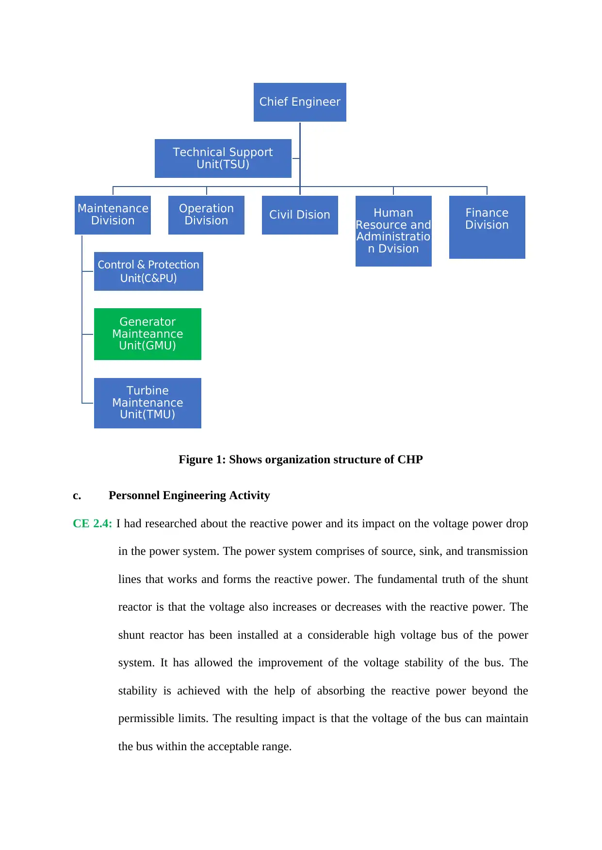
Figure 1: Shows organization structure of CHP
c. Personnel Engineering Activity
CE 2.4: I had researched about the reactive power and its impact on the voltage power drop
in the power system. The power system comprises of source, sink, and transmission
lines that works and forms the reactive power. The fundamental truth of the shunt
reactor is that the voltage also increases or decreases with the reactive power. The
shunt reactor has been installed at a considerable high voltage bus of the power
system. It has allowed the improvement of the voltage stability of the bus. The
stability is achieved with the help of absorbing the reactive power beyond the
permissible limits. The resulting impact is that the voltage of the bus can maintain
the bus within the acceptable range.
Chief Engineer
Maintenance
Division
Control & Protection
Unit(C&PU)
Generator
Mainteannce
Unit(GMU)
Turbine
Maintenance
Unit(TMU)
Operation
Division Civil Dision Human
Resource and
Administratio
n Dvision
Finance
Division
Technical Support
Unit(TSU)
⊘ This is a preview!⊘
Do you want full access?
Subscribe today to unlock all pages.

Trusted by 1+ million students worldwide
CE 2.5: I had done analysis for the voltage data of the bus and the operational division of the
Chhukha Hydropower Plant had maintained the data for 2010, 2011, and 2012. I
collected the data from the operational division for the mentioned three years and it
helped in finding the deviation of the voltage data from the standard value. To check
out the accuracy of the data stored, I even cross checked the collected data by asking
about it from the various shift engineers. The collected data were,
2010 -> 230 KV
2011 -> 228 KV
2012 -> 225 KV
I did the trend analysis of the data in Ms-Excel to observe the bus voltage over the
years and it came out that the trended and calculated voltage has shown improvement
in the profile. The values were referred to the standard IEC/IEEE/CIGRE and other
international relevant journals were checked for checking the permissible limits of
220KV. The average voltage values were determined for each of the year and the
values came close to the permissible limits. Hence the voltage issue problem was
ruled out from Chhukha Hydropower Plant.
CE 2.6: I did similar analysis on the reactor power of the 4 Chhukha Hydropower Plant’s
generators. The grid system experienced that was prior to the stator winding failure
incident of September 2011 was also analysed by me. I found out about the 4
generators from the operational log books which were present in the operational log
book. The four generators had absorbed a total of 93 Mvar of reactive power. The
National Load Dispatch Centre (NLDC) at Thimphu had been looking after the
complete power system of Bhutan and I had compared that data with the data of
absorbed reactive power of 93 Mvar. Moreover, I used the concept of generator
Paraphrase This Document
Need a fresh take? Get an instant paraphrase of this document with our AI Paraphraser
capability curve for studying the reactive power that can be maximum allowable and
the feasible operating range. These were the limits of the generator that can be
absorbed or delivered without any issue. The study of capability curve yielded that
approximately 40 Mvar of reactive power can be managed by the generator and it is
the maximum feasible limits of the generator working at the power factor of 0.9.
Hence, it provided the conclusion that the incoming 93 Mvar of reactive power had
not caused any stress on the system or machine’s capability.
CE 2.7: The validation of the safe limits further for the reactive power and voltage at
Chhukha Hydropower Plant was carried on by me. I had developed single line
diagram for Bhutan Power System Network connecting the simulation use at some of
Indian parts. I have to visit each of the power plants and substations of Bhutan Power
System Network so that I can draw a single line diagram for the power system
network. It helped me in getting detailed parametric values of transformers,
generators, and transmission lines along with the status of the shunt reactor at each of
the facility. I had to wear a Personal Protective Equipment (PPE) while I was visiting
the places for my safety. I even found out about the power flow direction of their
system. I had to assure them for sharing the information due to the threat of the data
being misused. However, I assured them that I would only use the data for research
purposes.
CE 2.8: I used load flow analysis at the electricity grid of whole Bhutan along with some
parts of electricity grid of India (till Purina). The software used for the load flow
analysis was MIPOWER software and it examined the behaviour of reactive power
and voltage for the Chhukha Power plant’s 220 KV bus. The following diagram
would represent the complete layout electricity grid of whole Bhutan along with some
parts of electricity grid of India (till Purina) used in MIPOWER software,
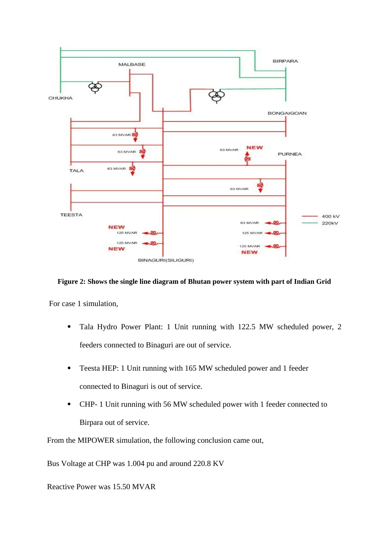
Figure 2: Shows the single line diagram of Bhutan power system with part of Indian Grid
For case 1 simulation,
Tala Hydro Power Plant: 1 Unit running with 122.5 MW scheduled power, 2
feeders connected to Binaguri are out of service.
Teesta HEP: 1 Unit running with 165 MW scheduled power and 1 feeder
connected to Binaguri is out of service.
CHP- 1 Unit running with 56 MW scheduled power with 1 feeder connected to
Birpara out of service.
From the MIPOWER simulation, the following conclusion came out,
Bus Voltage at CHP was 1.004 pu and around 220.8 KV
Reactive Power was 15.50 MVAR
⊘ This is a preview!⊘
Do you want full access?
Subscribe today to unlock all pages.

Trusted by 1+ million students worldwide
For case 2 simulation, shunt reactors were not connected to the power grid,
Bus Voltage at CHP was 1.046 pu and around 230.12 KV
Reactive Power was 35 MVAR
For case 3 simulation, shunt reactors were connected with the 220 KV bus of CHP
Bus Voltage at CHP was 0.997 pu and around 219.34 KV
Reactive Power was 8.75 MVAR
CE 2.9: I have completed the project of restoration of the stator bars for the development of
the improved operations. The completion date of the project was before the final
deadline given by the management. The management had applauded me for the quick
work and the smart actions for the project. The management boards were impressed as
the restoration had helped in reducing the loss of power generation and additionally for
completing the project in two less days than expected.
d. Summary
CE 2.10: I have completed the project of restoration of the stator bars for the development of
the improved operations. The completion date of the project was before the final
deadline given by the management. The management had applauded me for the quick
work and the smart actions for the project. The management boards were impressed as
the restoration had helped in reducing the loss of power generation and additionally
for completing the project in two less days than expected.
1 out of 7
Your All-in-One AI-Powered Toolkit for Academic Success.
+13062052269
info@desklib.com
Available 24*7 on WhatsApp / Email
![[object Object]](/_next/static/media/star-bottom.7253800d.svg)
Unlock your academic potential
© 2024 | Zucol Services PVT LTD | All rights reserved.


