Structural Analysis of Walkway
VerifiedAdded on 2023/04/06
|14
|1159
|257
AI Summary
This technical report provides a detailed analysis of the structural integrity of a walkway using Ansys software. It examines the plastic deformation, stress levels, and strain values. The report suggests solutions to improve the structure's performance by inserting ribs and support angles.
Contribute Materials
Your contribution can guide someone’s learning journey. Share your
documents today.
PROJECT TITLE:
STRUCTURAL ANALYSIS OF WALKWAY
1
REPORT NO :- DATE :
16/03/18
PREPARED CHECKED APPROVED
DOCUMENT CHANGE NOTE :-
REV NO BY DESCRIPTION APPROVED DATE
STRUCTURAL ANALYSIS OF WALKWAY
1
REPORT NO :- DATE :
16/03/18
PREPARED CHECKED APPROVED
DOCUMENT CHANGE NOTE :-
REV NO BY DESCRIPTION APPROVED DATE
Secure Best Marks with AI Grader
Need help grading? Try our AI Grader for instant feedback on your assignments.
2
Abstract
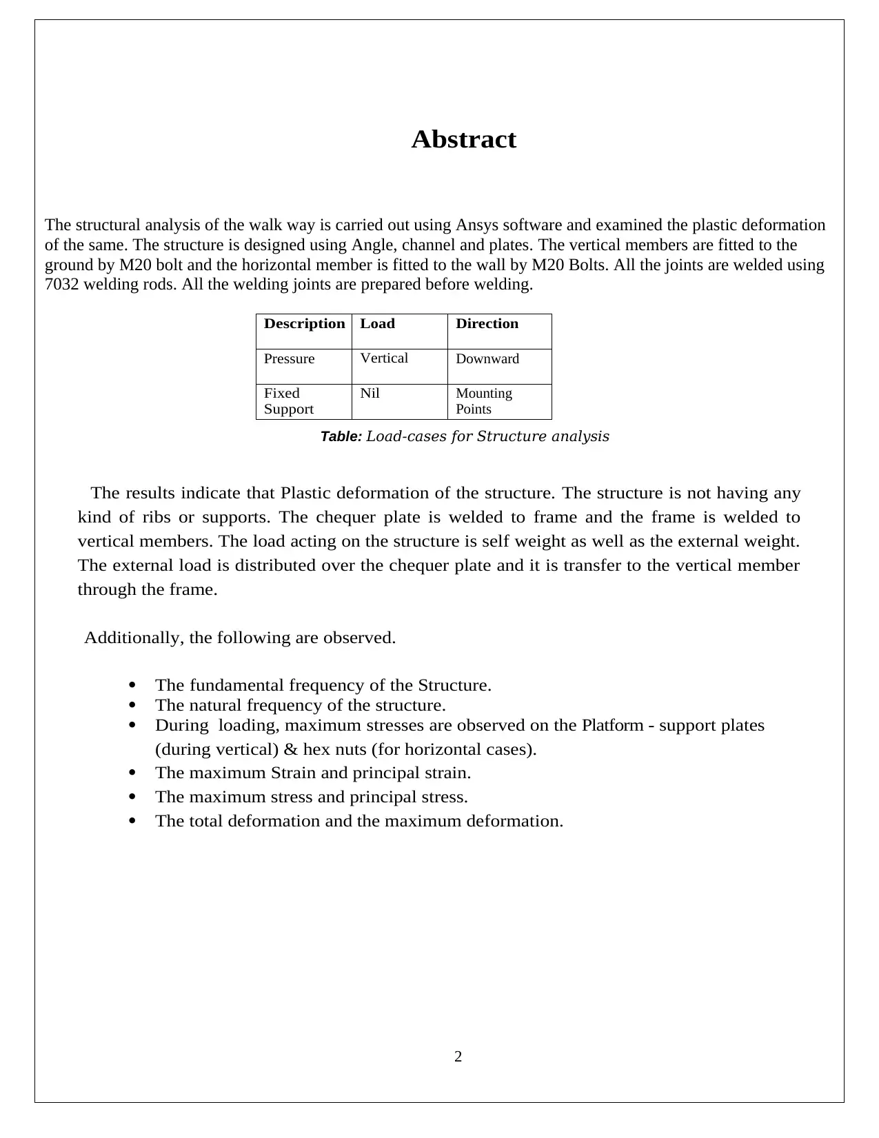
The structural analysis of the walk way is carried out using Ansys software and examined the plastic deformation
of the same. The structure is designed using Angle, channel and plates. The vertical members are fitted to the
ground by M20 bolt and the horizontal member is fitted to the wall by M20 Bolts. All the joints are welded using
7032 welding rods. All the welding joints are prepared before welding.
Description Load Direction
Pressure Vertical Downward
Fixed
Support
Nil Mounting
Points
Table: Load-cases for Structure analysis
The results indicate that Plastic deformation of the structure. The structure is not having any
kind of ribs or supports. The chequer plate is welded to frame and the frame is welded to
vertical members. The load acting on the structure is self weight as well as the external weight.
The external load is distributed over the chequer plate and it is transfer to the vertical member
through the frame.
Additionally, the following are observed.
The fundamental frequency of the Structure.
The natural frequency of the structure.
During loading, maximum stresses are observed on the Platform - support plates
(during vertical) & hex nuts (for horizontal cases).
The maximum Strain and principal strain.
The maximum stress and principal stress.
The total deformation and the maximum deformation.
Abstract
The structural analysis of the walk way is carried out using Ansys software and examined the plastic deformation
of the same. The structure is designed using Angle, channel and plates. The vertical members are fitted to the
ground by M20 bolt and the horizontal member is fitted to the wall by M20 Bolts. All the joints are welded using
7032 welding rods. All the welding joints are prepared before welding.
Description Load Direction
Pressure Vertical Downward
Fixed
Support
Nil Mounting
Points
Table: Load-cases for Structure analysis
The results indicate that Plastic deformation of the structure. The structure is not having any
kind of ribs or supports. The chequer plate is welded to frame and the frame is welded to
vertical members. The load acting on the structure is self weight as well as the external weight.
The external load is distributed over the chequer plate and it is transfer to the vertical member
through the frame.
Additionally, the following are observed.
The fundamental frequency of the Structure.
The natural frequency of the structure.
During loading, maximum stresses are observed on the Platform - support plates
(during vertical) & hex nuts (for horizontal cases).
The maximum Strain and principal strain.
The maximum stress and principal stress.
The total deformation and the maximum deformation.
3
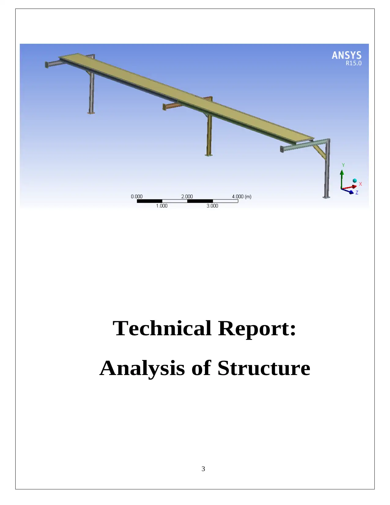
Technical Report:
Analysis of Structure
Technical Report:
Analysis of Structure
4
Analysis of Structure
CONTENTS P.No.
Analysis of Structure
CONTENTS P.No.
Secure Best Marks with AI Grader
Need help grading? Try our AI Grader for instant feedback on your assignments.
5
Analysis of Structure:
Summary
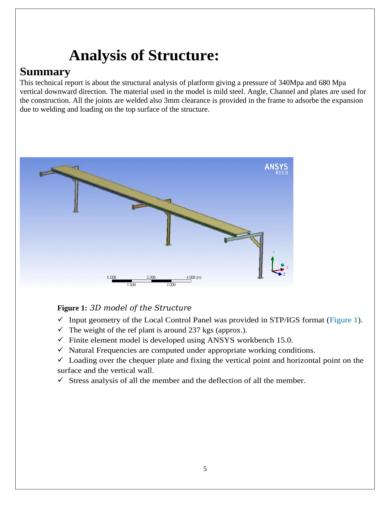
This technical report is about the structural analysis of platform giving a pressure of 340Mpa and 680 Mpa
vertical downward direction. The material used in the model is mild steel. Angle, Channel and plates are used for
the construction. All the joints are welded also 3mm clearance is provided in the frame to adsorbe the expansion
due to welding and loading on the top surface of the structure.
Figure 1: 3D model of the Structure
Input geometry of the Local Control Panel was provided in STP/IGS format (Figure 1).
The weight of the ref plant is around 237 kgs (approx.).
Finite element model is developed using ANSYS workbench 15.0.
Natural Frequencies are computed under appropriate working conditions.
Loading over the chequer plate and fixing the vertical point and horizontal point on the
surface and the vertical wall.
Stress analysis of all the member and the deflection of all the member.
Analysis of Structure:
Summary
This technical report is about the structural analysis of platform giving a pressure of 340Mpa and 680 Mpa
vertical downward direction. The material used in the model is mild steel. Angle, Channel and plates are used for
the construction. All the joints are welded also 3mm clearance is provided in the frame to adsorbe the expansion
due to welding and loading on the top surface of the structure.
Figure 1: 3D model of the Structure
Input geometry of the Local Control Panel was provided in STP/IGS format (Figure 1).
The weight of the ref plant is around 237 kgs (approx.).
Finite element model is developed using ANSYS workbench 15.0.
Natural Frequencies are computed under appropriate working conditions.
Loading over the chequer plate and fixing the vertical point and horizontal point on the
surface and the vertical wall.
Stress analysis of all the member and the deflection of all the member.
6
Problem Definition and Input Supplied
Scope of Work
The Objective of the analysis is to perform a computer aided simulation so as to ascertain
the mechanical integrity of the Structure when subjected to Load Environment. The
following parameter are investigated and illustrated in the report.
Deformations at points of interest.
Von-mises / normal stress at various components.
The maximum strain
The principal strain
The maximum stress
The principal stress
Total deformation
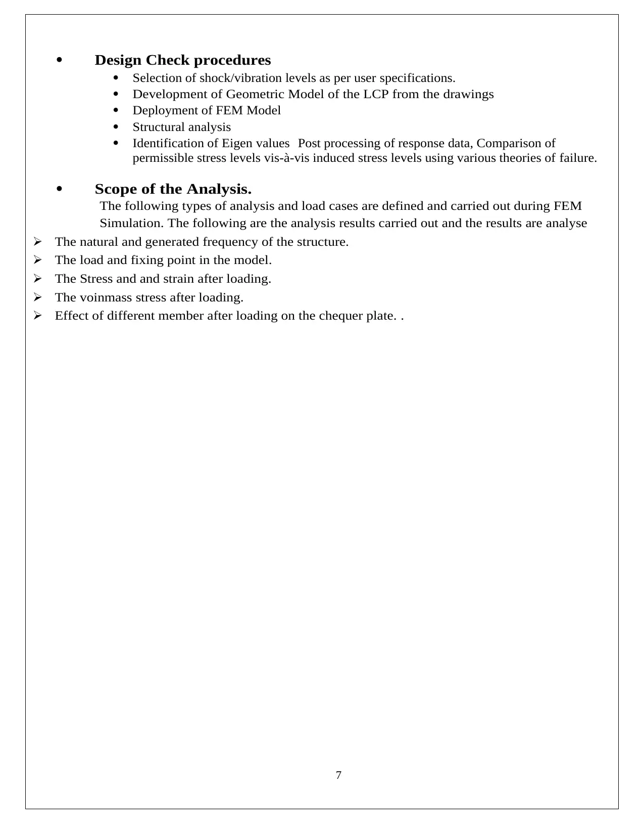
Specification of Analysis
Inputs Provided
Title
1 Overhead
Walkway.STP
Material
Data
Table 3: Data Provided
Part Name Material
Structure Mild Steel
Table 4: Material Data
Purpose
Structure is required to operate in load environment qualifying Structure standards. The
analysis is to be carried out to ensure smooth performance and satisfactory functioning in
environment. Also check the plastic strain of the structure. As the model has no ribs and
supports we can expect the plastic deformation in the structure but we need to check the values
for computational and FEA analysis.
Problem Definition and Input Supplied
Scope of Work
The Objective of the analysis is to perform a computer aided simulation so as to ascertain
the mechanical integrity of the Structure when subjected to Load Environment. The
following parameter are investigated and illustrated in the report.
Deformations at points of interest.
Von-mises / normal stress at various components.
The maximum strain
The principal strain
The maximum stress
The principal stress
Total deformation
Specification of Analysis
Inputs Provided
Title
1 Overhead
Walkway.STP
Material
Data
Table 3: Data Provided
Part Name Material
Structure Mild Steel
Table 4: Material Data
Purpose
Structure is required to operate in load environment qualifying Structure standards. The
analysis is to be carried out to ensure smooth performance and satisfactory functioning in
environment. Also check the plastic strain of the structure. As the model has no ribs and
supports we can expect the plastic deformation in the structure but we need to check the values
for computational and FEA analysis.
7
Design Check procedures
Selection of shock/vibration levels as per user specifications.
Development of Geometric Model of the LCP from the drawings
Deployment of FEM Model
Structural analysis
Identification of Eigen values Post processing of response data, Comparison of
permissible stress levels vis-à-vis induced stress levels using various theories of failure.
Scope of the Analysis.
The following types of analysis and load cases are defined and carried out during FEM
Simulation. The following are the analysis results carried out and the results are analyse
The natural and generated frequency of the structure.
The load and fixing point in the model.
The Stress and and strain after loading.
The voinmass stress after loading.
Effect of different member after loading on the chequer plate. .
Paraphrase This Document
Need a fresh take? Get an instant paraphrase of this document with our AI Paraphraser
8
3.0 Development of FEM Model
Software Used
The computation is performed using the finite element analysis (FEA) program ANSYS®. The
theoretical basis is documented in the ANSYS® THEORETICAL MANUAL. ANSYS® is
developed by ANSYS Inc., Canonsburg Pennsylvania. FEA Model (FEM) of the refrigeration plant
has been constructed and the finite element model (meshing) has been generated with ANSYS
Workbench
15.0 environment. It is then loaded into the workbench environment.
Inputs Used
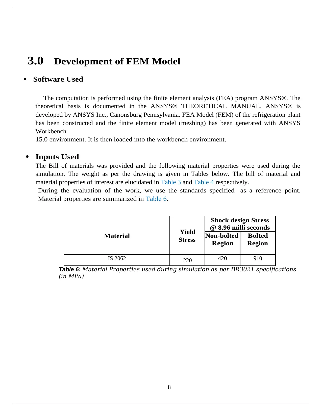
The Bill of materials was provided and the following material properties were used during the
simulation. The weight as per the drawing is given in Tables below. The bill of material and
material properties of interest are elucidated in Table 3 and Table 4 respectively.
During the evaluation of the work, we use the standards specified as a reference point.
Material properties are summarized in Table 6.
Material Yield
Stress
Shock design Stress
@ 8.96 milli seconds
Non-bolted
Region
Bolted
Region
IS 2062 220 420 910
Table 6: Material Properties used during simulation as per BR3021 specifications
(in MPa)
3.0 Development of FEM Model
Software Used
The computation is performed using the finite element analysis (FEA) program ANSYS®. The
theoretical basis is documented in the ANSYS® THEORETICAL MANUAL. ANSYS® is
developed by ANSYS Inc., Canonsburg Pennsylvania. FEA Model (FEM) of the refrigeration plant
has been constructed and the finite element model (meshing) has been generated with ANSYS
Workbench
15.0 environment. It is then loaded into the workbench environment.
Inputs Used
The Bill of materials was provided and the following material properties were used during the
simulation. The weight as per the drawing is given in Tables below. The bill of material and
material properties of interest are elucidated in Table 3 and Table 4 respectively.
During the evaluation of the work, we use the standards specified as a reference point.
Material properties are summarized in Table 6.
Material Yield
Stress
Shock design Stress
@ 8.96 milli seconds
Non-bolted
Region
Bolted
Region
IS 2062 220 420 910
Table 6: Material Properties used during simulation as per BR3021 specifications
(in MPa)
9
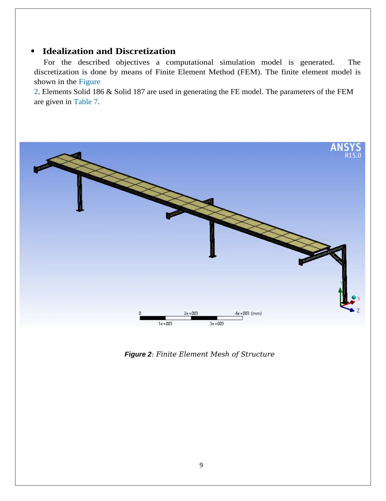
Idealization and Discretization
For the described objectives a computational simulation model is generated. The
discretization is done by means of Finite Element Method (FEM). The finite element model is
shown in the Figure
2. Elements Solid 186 & Solid 187 are used in generating the FE model. The parameters of the FEM
are given in Table 7.
Figure 2: Finite Element Mesh of Structure
10
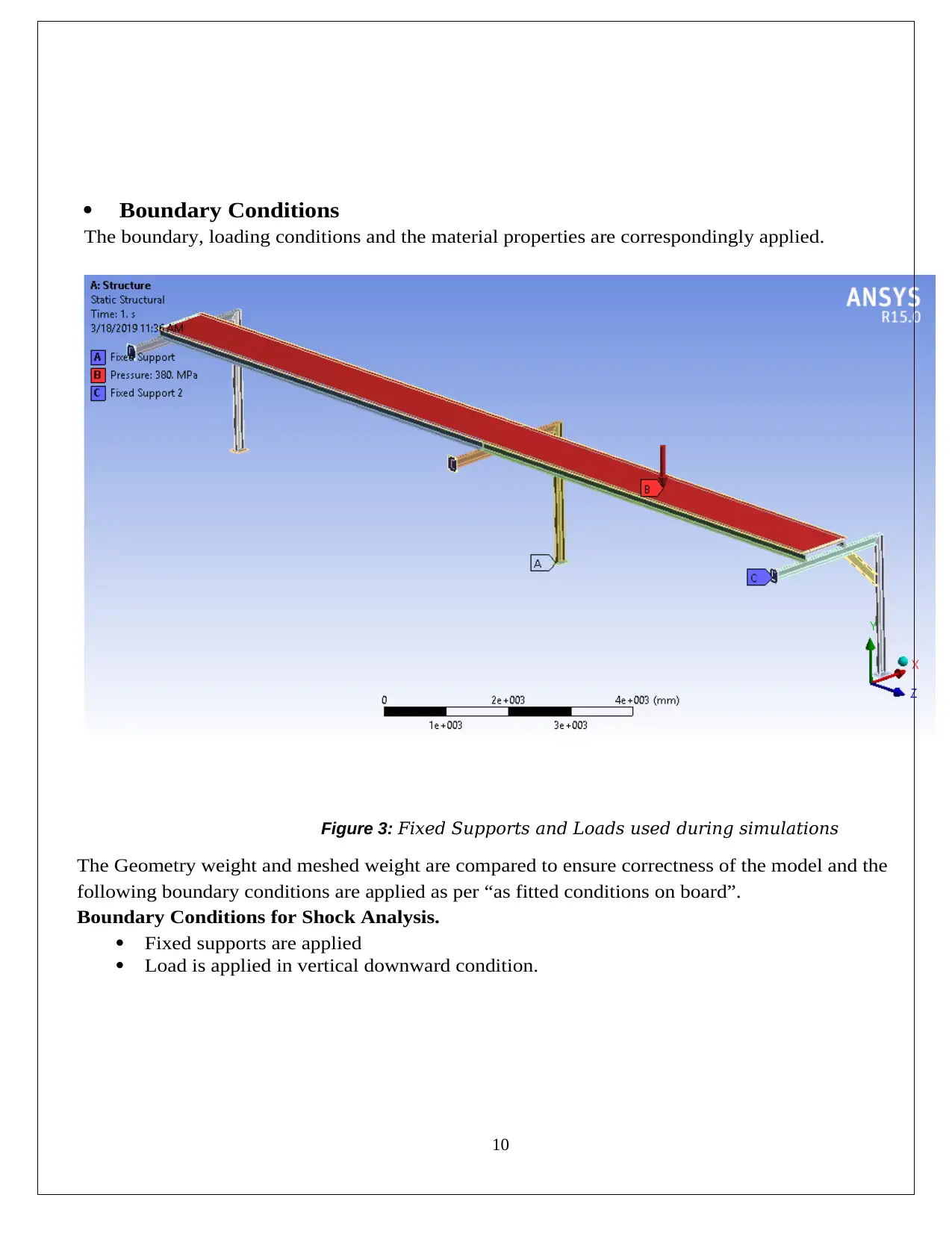
Boundary Conditions
The boundary, loading conditions and the material properties are correspondingly applied.
Figure 3: Fixed Supports and Loads used during simulations
The Geometry weight and meshed weight are compared to ensure correctness of the model and the
following boundary conditions are applied as per “as fitted conditions on board”.
Boundary Conditions for Shock Analysis.
Fixed supports are applied
Load is applied in vertical downward condition.
Secure Best Marks with AI Grader
Need help grading? Try our AI Grader for instant feedback on your assignments.
11
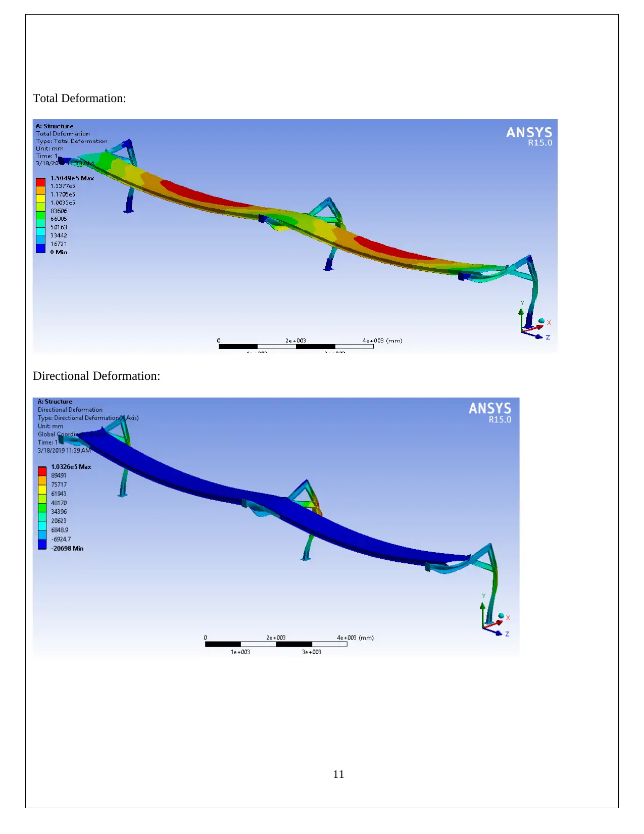
Total Deformation:
Directional Deformation:
Total Deformation:
Directional Deformation:
12
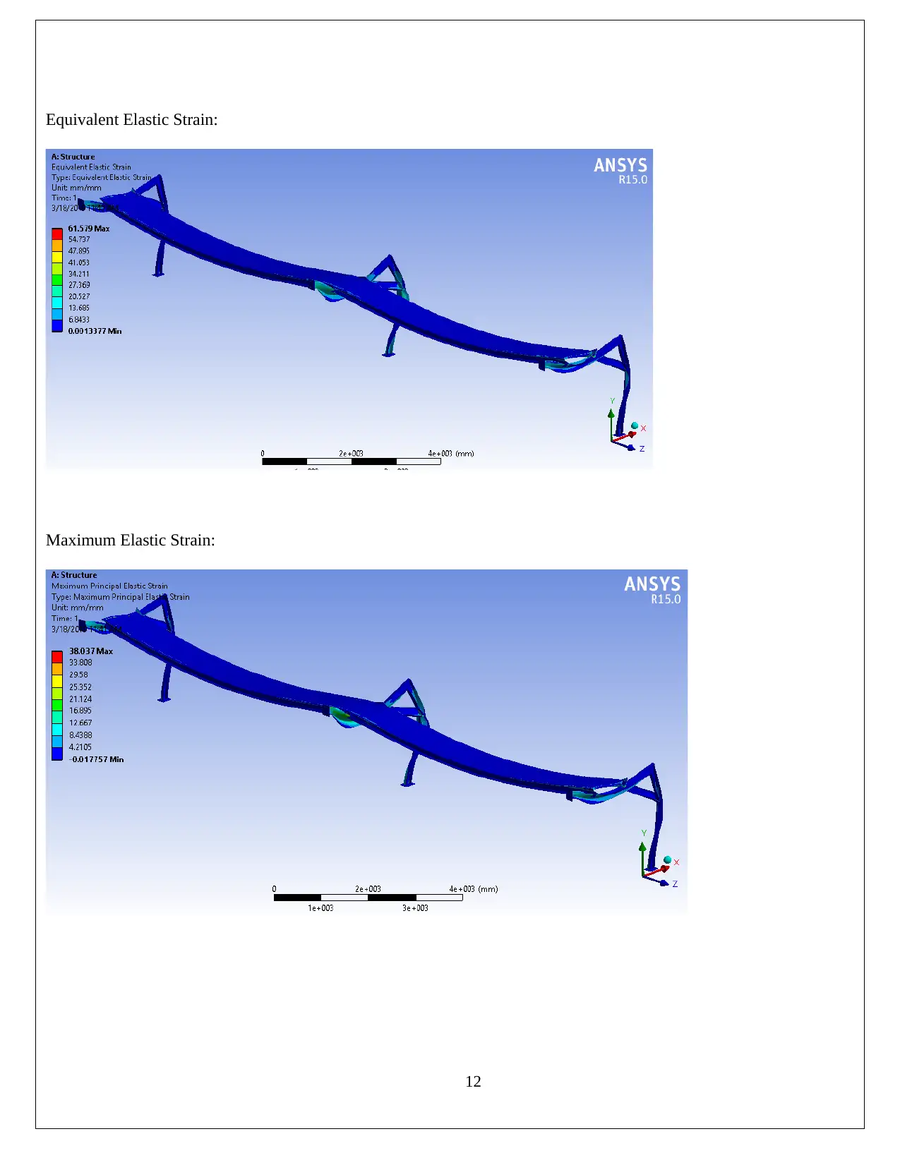
Equivalent Elastic Strain:
Maximum Elastic Strain:
Equivalent Elastic Strain:
Maximum Elastic Strain:
13
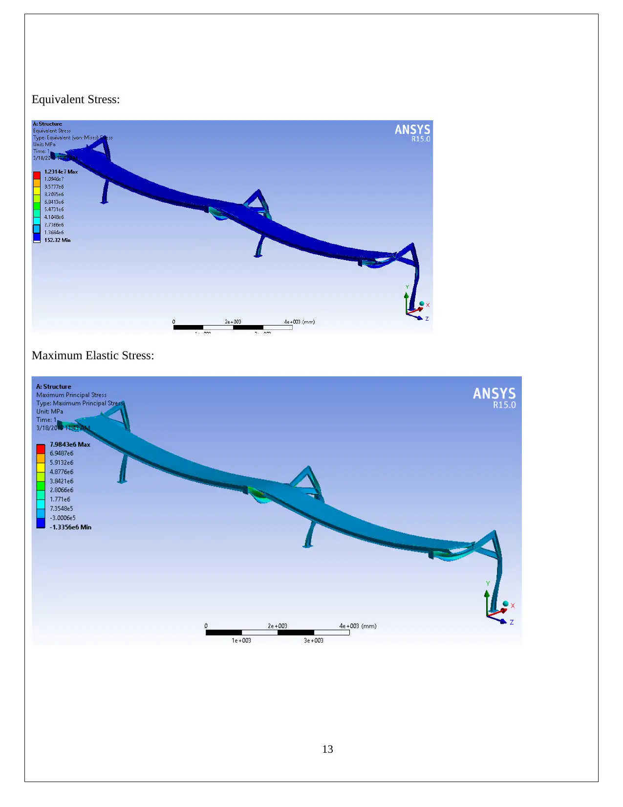
Equivalent Stress:
Maximum Elastic Stress:
Equivalent Stress:
Maximum Elastic Stress:
Paraphrase This Document
Need a fresh take? Get an instant paraphrase of this document with our AI Paraphraser
14
o The stresses also peak for shock loading along z axis.
o Additionally, all the stresses are exceeding the permissible limits given in Table 6.
o The maximum displacements beyond expected lines matching the theoretical
understanding and do not interfere with the overall functionality.
Conclusions
A numerical analysis to ascertain the mechanical integrity of the Structure has been carried
out as per standards. The results indicate that the stress level and the strain values are high and
the material deformation goes into the plastic region. The suggestion to aviod the high stress and
strain level by inserting ribs and support angles below the platform.
1 out of 14


Your All-in-One AI-Powered Toolkit for Academic Success.
+13062052269
info@desklib.com
Available 24*7 on WhatsApp / Email
![[object Object]](/_next/static/media/star-bottom.7253800d.svg)
Unlock your academic potential
© 2024 | Zucol Services PVT LTD | All rights reserved.