Pump and Pipe Sizing Calculation for Chiller Water System
VerifiedAdded on 2023/04/22
|5
|1140
|375
AI Summary
This article explains how to do pump sizing calculation for chiller water system to determine differential head required to be generated by pump based on suction and discharge conditions. It covers the calculation of pressure at pump suction and discharge, differential head, hydraulic power, and NPSH available. The article also discusses the material selection for piping.
Contribute Materials
Your contribution can guide someone’s learning journey. Share your
documents today.
Pump and Pipe Sizing Calculation:
Pump Head Calculation for Chiller water System
Pump head is the total resistance that a pump must overcome
1. Velocity Head
Accelerating water from a standstill or low velocity at the starting point to a velocity at an ending
point requires high energy. In the closed system the starting point as same as the end point.
Therefore the beginning velocity is same as the ending velocity, so velocity head is not a
consideration.
2. Pressure Head
When liquid is pumped from a vessel at one pressure to a vessel at another vessel, pressure
head exist. Common application is condensate pump and boiler feed pump. Condensate pumps often
deliver water from an atmospheric receiver to a deaerator operating at 5 PSIG, meaning that in
addition to other heads, the pump must overcome a pressure head of 5 PSIG.
3. Friction Head
This is also called pressure drop. When fluid flows through any system component, friction
results. This causes a loss in pressure. Components causing friction include boilers, chillers, piping,
heat ex changers, coils, valves, and fittings. The pump must overcome this friction. Friction head is
usually expressed in units called "feet of head."A foot of friction head is equal to lifting the fluid one
foot of static height.
4. Static Head
Static head represents the net change in height, in feet, that the pump must overcome. It applies
only in open systems. Note that in a closed loop system, the static head is zero because the fluid on
one side of the system pushes the fluid up the other side of the system, so the pump does not need to
overcome any elevation.
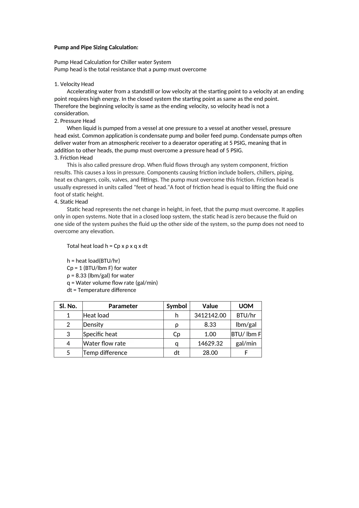
Total heat load h = Cp x ρ x q x dt
h = heat load(BTU/hr)
Cp = 1 (BTU/lbm F) for water
ρ = 8.33 (lbm/gal) for water
q = Water volume flow rate (gal/min)
dt = Temperature difference
Sl. No. Parameter Symbol Value UOM
1 Heat load h 3412142.00 BTU/hr
2 Density ρ 8.33 lbm/gal
3 Specific heat Cp 1.00 BTU/ lbm F
4 Water flow rate q 14629.32 gal/min
5 Temp difference dt 28.00 F
Secure Best Marks with AI Grader
Need help grading? Try our AI Grader for instant feedback on your assignments.
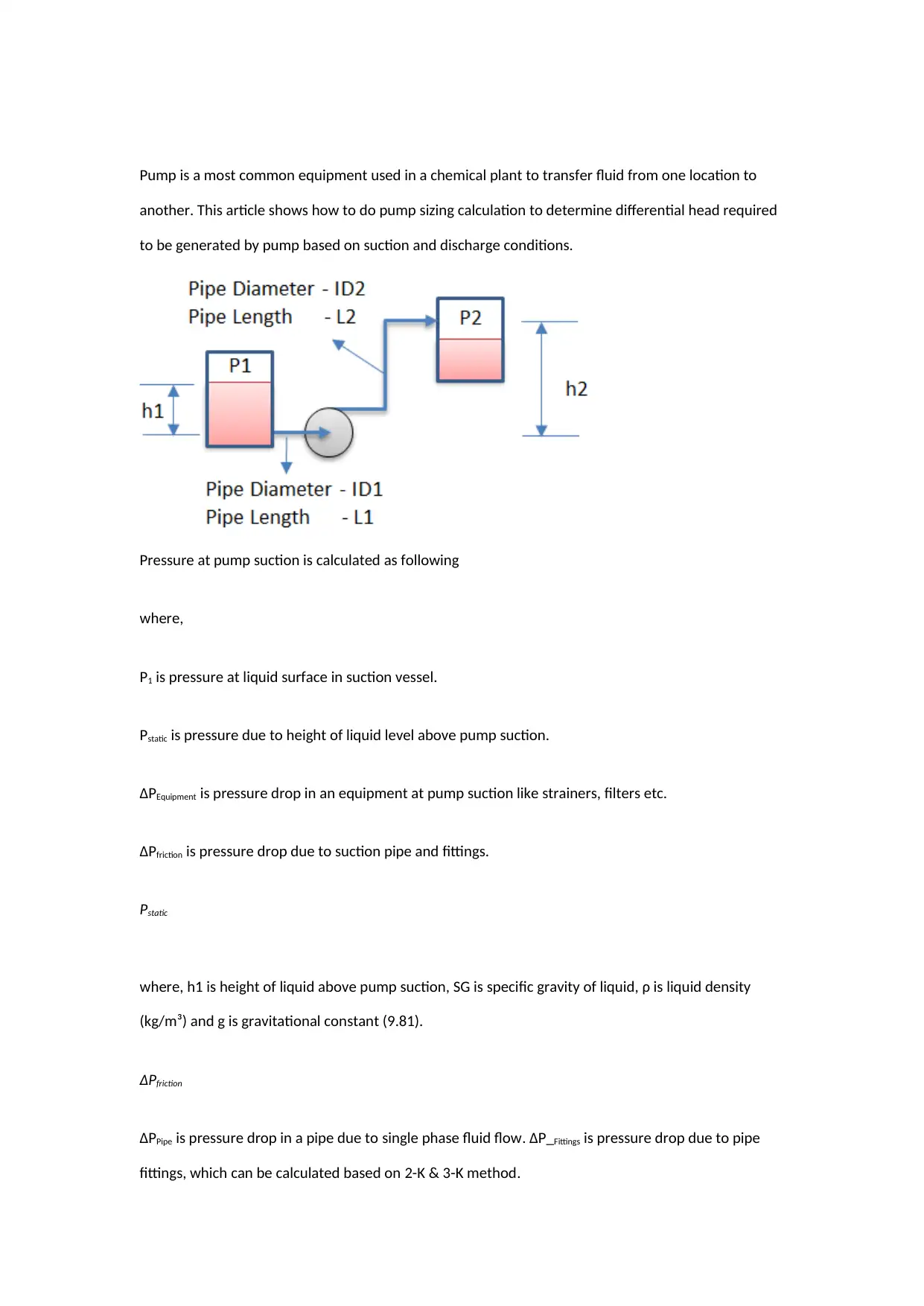
Pump is a most common equipment used in a chemical plant to transfer fluid from one location to
another. This article shows how to do pump sizing calculation to determine differential head required
to be generated by pump based on suction and discharge conditions.
Pressure at pump suction is calculated as following
where,
P1 is pressure at liquid surface in suction vessel.
Pstatic is pressure due to height of liquid level above pump suction.
ΔPEquipment is pressure drop in an equipment at pump suction like strainers, filters etc.
ΔPfriction is pressure drop due to suction pipe and fittings.
Pstatic
where, h1 is height of liquid above pump suction, SG is specific gravity of liquid, ρ is liquid density
(kg/m³) and g is gravitational constant (9.81).
ΔPfriction
ΔPPipe is pressure drop in a pipe due to single phase fluid flow. ΔP_Fittings is pressure drop due to pipe
fittings, which can be calculated based on 2-K & 3-K method.
Discharge Pressure
Pressure at pump discharge is calculated as following
where,
P2 is pressure at liquid surface in discharge vessel.
Pstatic is pressure due to height of liquid level above pump suction.
ΔPEquipment is pressure drop in equipment at pump discharge like heat exchangers, control valve,
flowmeter, valves etc.
ΔPfriction is pressure drop due to suction pipe and fittings.
Pstatic
where, h2 is height of liquid above pump suction at which liquid is to be discharged.
ΔPfriction is calculated in similar way as mentioned above for discharge piping.
Differential Head
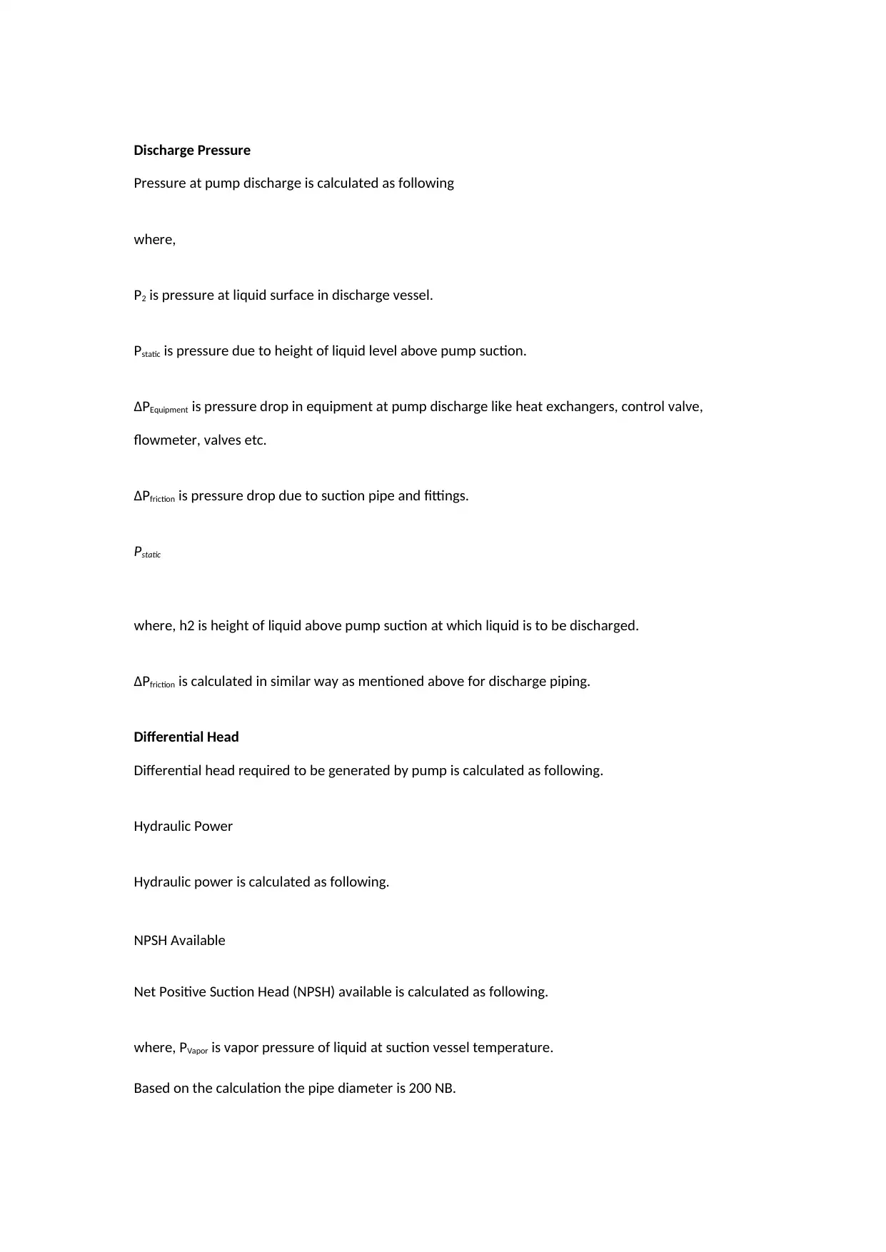
Differential head required to be generated by pump is calculated as following.
Hydraulic Power
Hydraulic power is calculated as following.
NPSH Available
Net Positive Suction Head (NPSH) available is calculated as following.
where, PVapor is vapor pressure of liquid at suction vessel temperature.
Based on the calculation the pipe diameter is 200 NB.
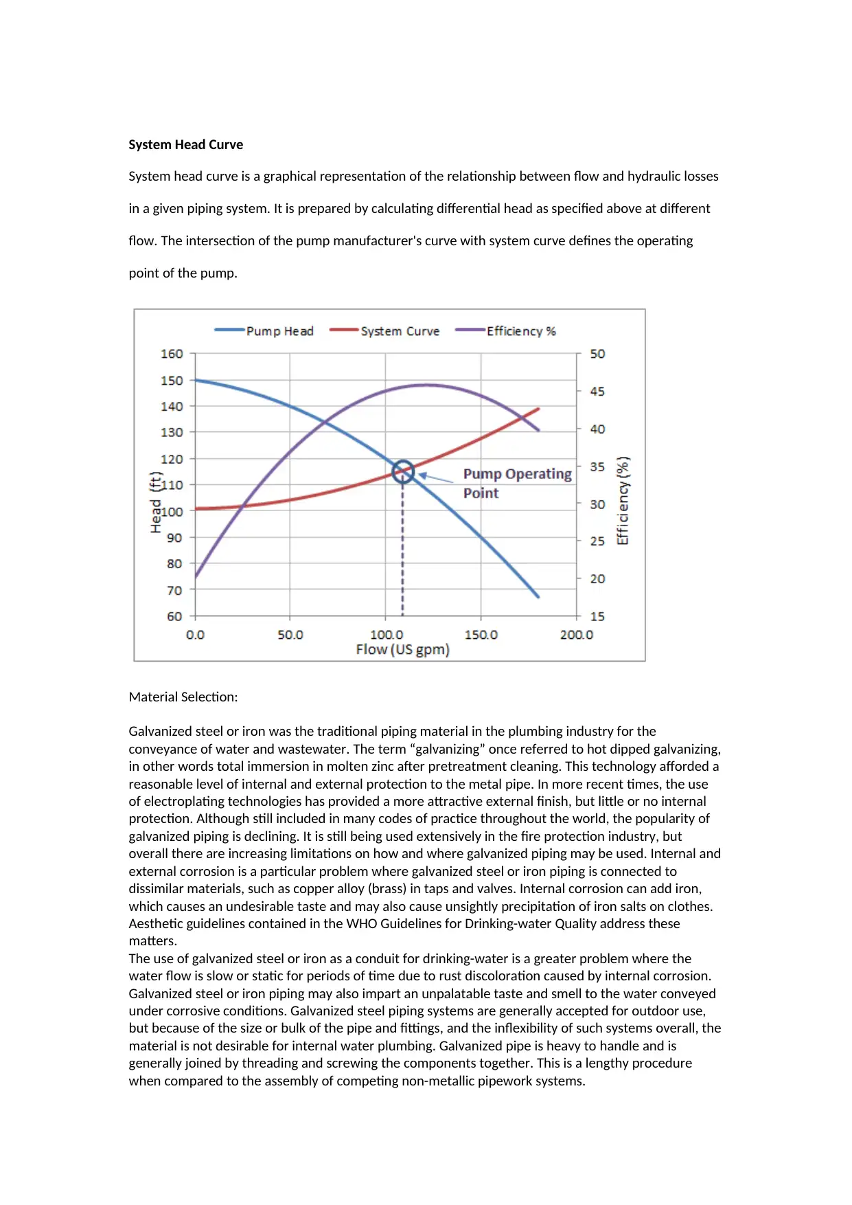
System Head Curve
System head curve is a graphical representation of the relationship between flow and hydraulic losses
in a given piping system. It is prepared by calculating differential head as specified above at different
flow. The intersection of the pump manufacturer's curve with system curve defines the operating
point of the pump.
Material Selection:
Galvanized steel or iron was the traditional piping material in the plumbing industry for the
conveyance of water and wastewater. The term “galvanizing” once referred to hot dipped galvanizing,
in other words total immersion in molten zinc after pretreatment cleaning. This technology afforded a
reasonable level of internal and external protection to the metal pipe. In more recent times, the use
of electroplating technologies has provided a more attractive external finish, but little or no internal
protection. Although still included in many codes of practice throughout the world, the popularity of
galvanized piping is declining. It is still being used extensively in the fire protection industry, but
overall there are increasing limitations on how and where galvanized piping may be used. Internal and
external corrosion is a particular problem where galvanized steel or iron piping is connected to
dissimilar materials, such as copper alloy (brass) in taps and valves. Internal corrosion can add iron,
which causes an undesirable taste and may also cause unsightly precipitation of iron salts on clothes.
Aesthetic guidelines contained in the WHO Guidelines for Drinking-water Quality address these
matters.
The use of galvanized steel or iron as a conduit for drinking-water is a greater problem where the
water flow is slow or static for periods of time due to rust discoloration caused by internal corrosion.
Galvanized steel or iron piping may also impart an unpalatable taste and smell to the water conveyed
under corrosive conditions. Galvanized steel piping systems are generally accepted for outdoor use,
but because of the size or bulk of the pipe and fittings, and the inflexibility of such systems overall, the
material is not desirable for internal water plumbing. Galvanized pipe is heavy to handle and is
generally joined by threading and screwing the components together. This is a lengthy procedure
when compared to the assembly of competing non-metallic pipework systems.
Secure Best Marks with AI Grader
Need help grading? Try our AI Grader for instant feedback on your assignments.
1 out of 5
Your All-in-One AI-Powered Toolkit for Academic Success.
+13062052269
info@desklib.com
Available 24*7 on WhatsApp / Email
Unlock your academic potential
© 2024 | Zucol Services PVT LTD | All rights reserved.