Pw Engineering Group Assignment Report
VerifiedAdded on 2022/09/05
|34
|5392
|27
AI Summary
Contribute Materials
Your contribution can guide someone’s learning journey. Share your
documents today.
PW Engineering Group 1
Paul Ward
ELECTRICAL ENGINEERING PROJECT.
PW Engineering Group
Smart Solar-powered Streetlamp Light control System off grid (Theoretical)
Title: Solar Street Lighting
Client: Engineering Council
Purchase order no: Theoretical 01
Document Ref: PW-001
Date: 30-07-2019
Paul Ward
ELECTRICAL ENGINEERING PROJECT.
PW Engineering Group
Smart Solar-powered Streetlamp Light control System off grid (Theoretical)
Title: Solar Street Lighting
Client: Engineering Council
Purchase order no: Theoretical 01
Document Ref: PW-001
Date: 30-07-2019
Secure Best Marks with AI Grader
Need help grading? Try our AI Grader for instant feedback on your assignments.
PW Engineering Group 2
ABSTRACT
Solar powered LED streetlight is an investment that is worth in operational cost as well friendlier
to the environment. With right optimization processes in harnessing of the solar power, the
energy sector can be greatly transformed dynamically replacing over dependent on fossil fuel
with greener energy sources. In this design proposal, the LED streetlight works by directly
utilizing energy generated from solar. During daytime when there is enough sunlight, the solar
panels absorb energy that is chemically stored in batteries for autonomous use during night
hours. The characteristics of good street light entails provision of uniform level of illumination
both horizontal and vertical geometry of the roadway. This is so vital in ensuring comfortable
vision for the road users that enhances their judgement while driving, riding or even the
pedestrian. In other words, street lights provide desired visual conditions for road users. There
are various types of streetlights manufactured with different technology. Depending on the cost
of operation as well as types of the road, different but specific types of the streetlights are
preferred. In this proposal, LED solar powered street light are dealt with.
PW Engineering Group 3
Contents
ABSTRACT...................................................................................................................................................2
1: THEORETICAL BACKGROUND..................................................................................................................4
1.1: Environmental temperature............................................................................................................5
1.2: Cloud Cover......................................................................................................................................6
1.3: Peak Sun Hour..................................................................................................................................6
1.4: Tilt and Orientation.........................................................................................................................7
1.5: Circuit Arrangement........................................................................................................................8
2: DESIGNING AND COMPONENT SIZING...................................................................................................9
2.1: Luminaire Calculations...................................................................................................................10
2.1.1: Maintenance Factor...............................................................................................................11
2.1.2: Lighting Intensity Calculations............................................................................................11
2.1.3: Luminance Uniformity..........................................................................................................11
2.1.4: Calculating Street Light Illumination Level (E)..................................................................12
2.1.5: Calculating Wattage for each street light pole luminaire...................................................13
2.2: Calculation of solar PV system required........................................................................................14
2.2.1: Sizing of the battery storage system.....................................................................................14
2.2.2: Micro-controller based charge controller............................................................................16
2.2.3: Sizing of the solar panel........................................................................................................17
2.3: Posts calculations...........................................................................................................................19
2.3.1: Pole Height.............................................................................................................................19
2.3.2: Setback...................................................................................................................................20
2.3.3: Overhang................................................................................................................................21
2.3.4: Outreach.................................................................................................................................21
2.3.5: Pole arm length......................................................................................................................22
2.3.6: Pole arm tilt angle..................................................................................................................22
2.3.7: Pole to pole spacing...............................................................................................................22
2.3.7: Battery installation box.........................................................................................................23
3: BUDGET ANALYSIS................................................................................................................................25
3.1: Monetary Budget...........................................................................................................................25
3.2: Time Budget...................................................................................................................................26
4: CONCLUSION.........................................................................................................................................27
REFERENCES..............................................................................................................................................28
PW Engineering Group 4
APPENDIX 1...............................................................................................................................................30
Lithium-ion battery pack; ION012120T16............................................................................................30
APPENDIX 2...............................................................................................................................................31
Off-grid LD135R9W LG solar panel.......................................................................................................31
APPENDIX 3...............................................................................................................................................32
30W LED streetlight..............................................................................................................................32
APPENDIX 4...............................................................................................................................................33
Micro controller based charge controller.............................................................................................33
Secure Best Marks with AI Grader
Need help grading? Try our AI Grader for instant feedback on your assignments.
PW Engineering Group 5
1: THEORETICAL BACKGROUND.
The capacity of solar insolation in the United Kingdom, (UK) forms the basis for scaling the size
of the solar PV system required. There are various conditions that directly influences the amount
of solar insolation from sunlight reaching the ground. These factors include;
Environmental temperature.
Amount of cloud cover.
Peak sun hour.
Coordinates which affects tilting angel of the solar panels
The aforementioned factors that affect solar PV system are explained briefly.
1.1: Environmental temperature.
According to the conversion technology of the photovoltaic cells, high temperatures tend to
reduce the efficiency of the cell. Above the standard temperature, 25oC, the conversion efficiency
of the panel reduces with increasing temperature. High temperature excites low electron
electrons at the bottom of the cell, whose potential counters electrons at the top of the cell that
have been excited by virtue of direct sunlight. As a result, the effective potential difference of the
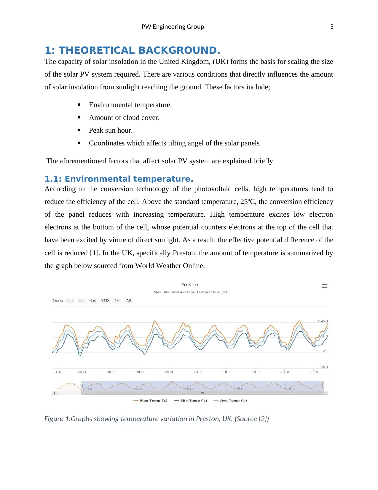
cell is reduced [1]. In the UK, specifically Preston, the amount of temperature is summarized by
the graph below sourced from World Weather Online.
Figure 1:Graphs showing temperature variation in Preston, UK, (Source [2])
1: THEORETICAL BACKGROUND.
The capacity of solar insolation in the United Kingdom, (UK) forms the basis for scaling the size
of the solar PV system required. There are various conditions that directly influences the amount
of solar insolation from sunlight reaching the ground. These factors include;
Environmental temperature.
Amount of cloud cover.
Peak sun hour.
Coordinates which affects tilting angel of the solar panels
The aforementioned factors that affect solar PV system are explained briefly.
1.1: Environmental temperature.
According to the conversion technology of the photovoltaic cells, high temperatures tend to
reduce the efficiency of the cell. Above the standard temperature, 25oC, the conversion efficiency
of the panel reduces with increasing temperature. High temperature excites low electron
electrons at the bottom of the cell, whose potential counters electrons at the top of the cell that
have been excited by virtue of direct sunlight. As a result, the effective potential difference of the
cell is reduced [1]. In the UK, specifically Preston, the amount of temperature is summarized by
the graph below sourced from World Weather Online.
Figure 1:Graphs showing temperature variation in Preston, UK, (Source [2])
PW Engineering Group 6
From the graph, the amount temperature received oscillates between 0oC to 18oC. This
temperature is below the standard temperature. Since low temperatures have no negative impact
on the amount of electricity generated by the solar cell, then therefore, the environment
temperature of the location is ideal for optimal performance of the photovoltaic cells [3].
Sunlight is the only source of solar energy. However, at extremely low temperatures during
winter season, snow cover on the solar panels blocks direct sunlight striking the panel’s surface
and thus albedo effects of the snow could lead to lower production when much light is reflected
away by the snow.
1.2: Cloud Cover.
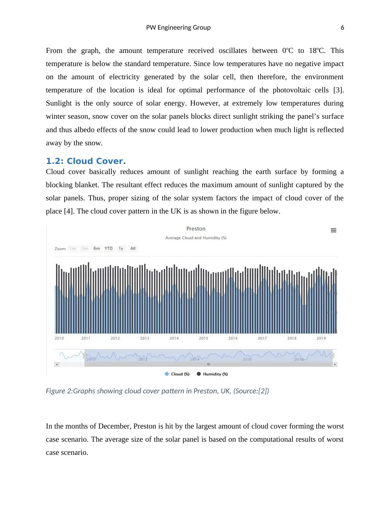
Cloud cover basically reduces amount of sunlight reaching the earth surface by forming a
blocking blanket. The resultant effect reduces the maximum amount of sunlight captured by the
solar panels. Thus, proper sizing of the solar system factors the impact of cloud cover of the
place [4]. The cloud cover pattern in the UK is as shown in the figure below.
Figure 2:Graphs showing cloud cover pattern in Preston, UK, (Source:[2])
In the months of December, Preston is hit by the largest amount of cloud cover forming the worst
case scenario. The average size of the solar panel is based on the computational results of worst
case scenario.
From the graph, the amount temperature received oscillates between 0oC to 18oC. This
temperature is below the standard temperature. Since low temperatures have no negative impact
on the amount of electricity generated by the solar cell, then therefore, the environment
temperature of the location is ideal for optimal performance of the photovoltaic cells [3].
Sunlight is the only source of solar energy. However, at extremely low temperatures during
winter season, snow cover on the solar panels blocks direct sunlight striking the panel’s surface
and thus albedo effects of the snow could lead to lower production when much light is reflected
away by the snow.
1.2: Cloud Cover.
Cloud cover basically reduces amount of sunlight reaching the earth surface by forming a
blocking blanket. The resultant effect reduces the maximum amount of sunlight captured by the
solar panels. Thus, proper sizing of the solar system factors the impact of cloud cover of the
place [4]. The cloud cover pattern in the UK is as shown in the figure below.
Figure 2:Graphs showing cloud cover pattern in Preston, UK, (Source:[2])
In the months of December, Preston is hit by the largest amount of cloud cover forming the worst
case scenario. The average size of the solar panel is based on the computational results of worst
case scenario.
PW Engineering Group 7
1.3: Peak Sun Hour.
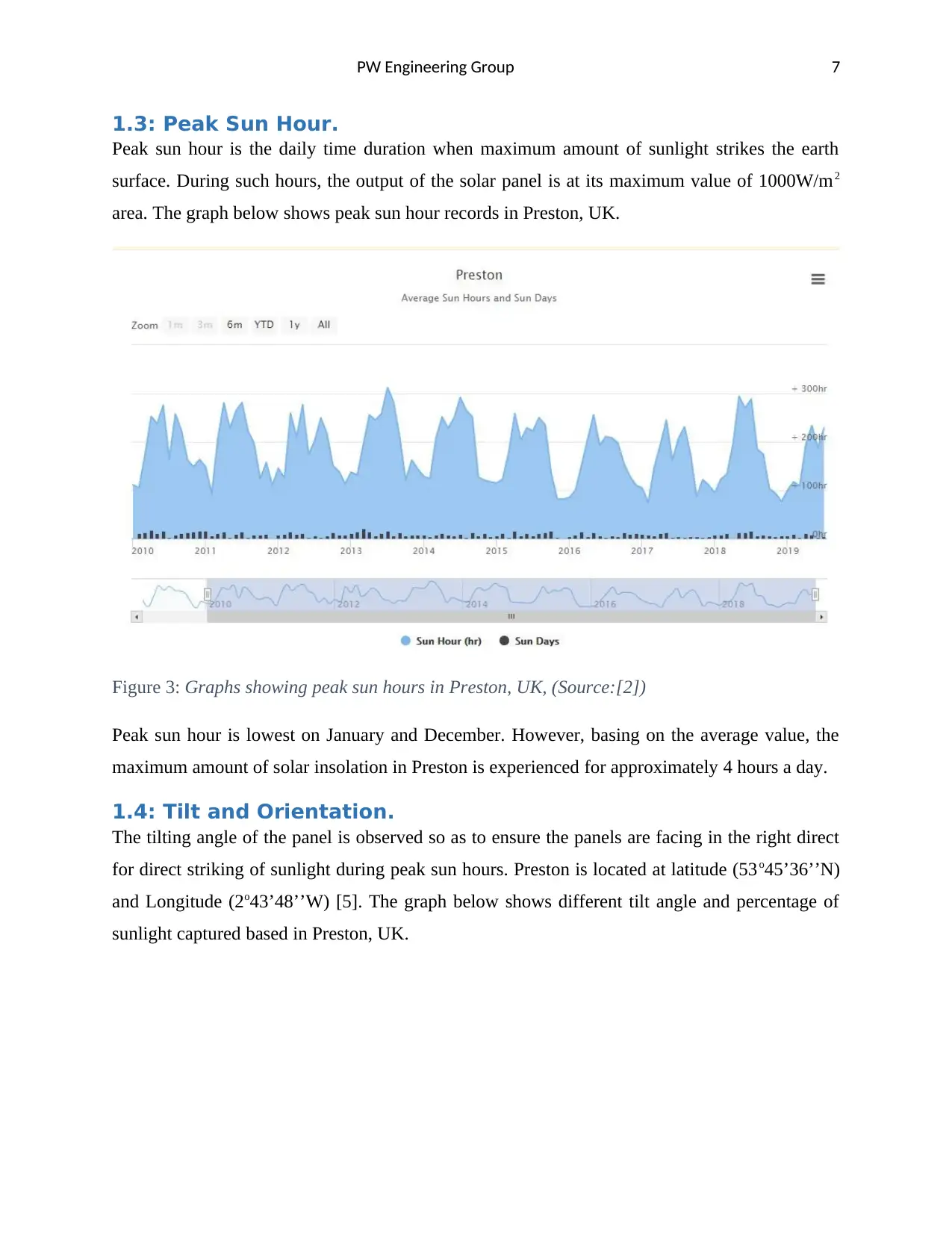
Peak sun hour is the daily time duration when maximum amount of sunlight strikes the earth
surface. During such hours, the output of the solar panel is at its maximum value of 1000W/m2
area. The graph below shows peak sun hour records in Preston, UK.
Figure 3: Graphs showing peak sun hours in Preston, UK, (Source:[2])
Peak sun hour is lowest on January and December. However, basing on the average value, the
maximum amount of solar insolation in Preston is experienced for approximately 4 hours a day.
1.4: Tilt and Orientation.
The tilting angle of the panel is observed so as to ensure the panels are facing in the right direct
for direct striking of sunlight during peak sun hours. Preston is located at latitude (53o45’36’’N)
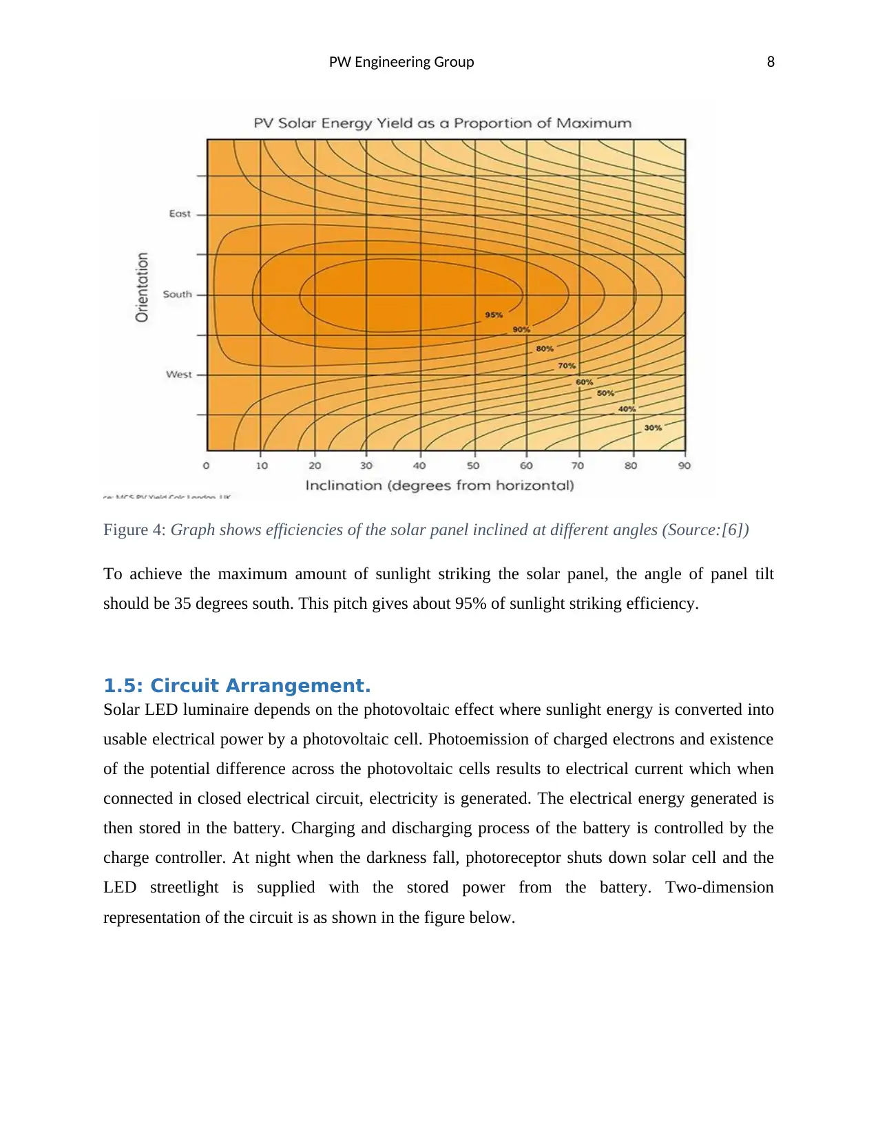
and Longitude (2o43’48’’W) [5]. The graph below shows different tilt angle and percentage of
sunlight captured based in Preston, UK.
1.3: Peak Sun Hour.
Peak sun hour is the daily time duration when maximum amount of sunlight strikes the earth
surface. During such hours, the output of the solar panel is at its maximum value of 1000W/m2
area. The graph below shows peak sun hour records in Preston, UK.
Figure 3: Graphs showing peak sun hours in Preston, UK, (Source:[2])
Peak sun hour is lowest on January and December. However, basing on the average value, the
maximum amount of solar insolation in Preston is experienced for approximately 4 hours a day.
1.4: Tilt and Orientation.
The tilting angle of the panel is observed so as to ensure the panels are facing in the right direct
for direct striking of sunlight during peak sun hours. Preston is located at latitude (53o45’36’’N)
and Longitude (2o43’48’’W) [5]. The graph below shows different tilt angle and percentage of
sunlight captured based in Preston, UK.
Paraphrase This Document
Need a fresh take? Get an instant paraphrase of this document with our AI Paraphraser
PW Engineering Group 8
Figure 4: Graph shows efficiencies of the solar panel inclined at different angles (Source:[6])
To achieve the maximum amount of sunlight striking the solar panel, the angle of panel tilt
should be 35 degrees south. This pitch gives about 95% of sunlight striking efficiency.
1.5: Circuit Arrangement.
Solar LED luminaire depends on the photovoltaic effect where sunlight energy is converted into
usable electrical power by a photovoltaic cell. Photoemission of charged electrons and existence
of the potential difference across the photovoltaic cells results to electrical current which when
connected in closed electrical circuit, electricity is generated. The electrical energy generated is
then stored in the battery. Charging and discharging process of the battery is controlled by the
charge controller. At night when the darkness fall, photoreceptor shuts down solar cell and the
LED streetlight is supplied with the stored power from the battery. Two-dimension
representation of the circuit is as shown in the figure below.
PW Engineering Group 9
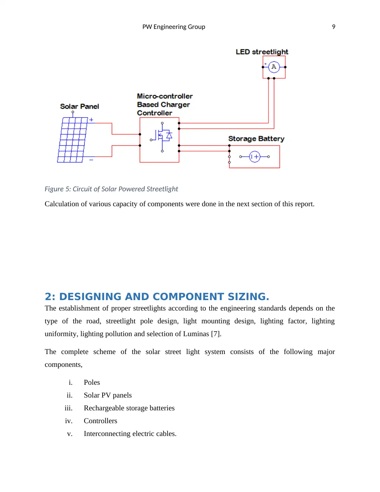
Figure 5: Circuit of Solar Powered Streetlight
Calculation of various capacity of components were done in the next section of this report.
2: DESIGNING AND COMPONENT SIZING.
The establishment of proper streetlights according to the engineering standards depends on the
type of the road, streetlight pole design, light mounting design, lighting factor, lighting
uniformity, lighting pollution and selection of Luminas [7].
The complete scheme of the solar street light system consists of the following major
components,
i. Poles
ii. Solar PV panels
iii. Rechargeable storage batteries
iv. Controllers
v. Interconnecting electric cables.
PW Engineering Group 10
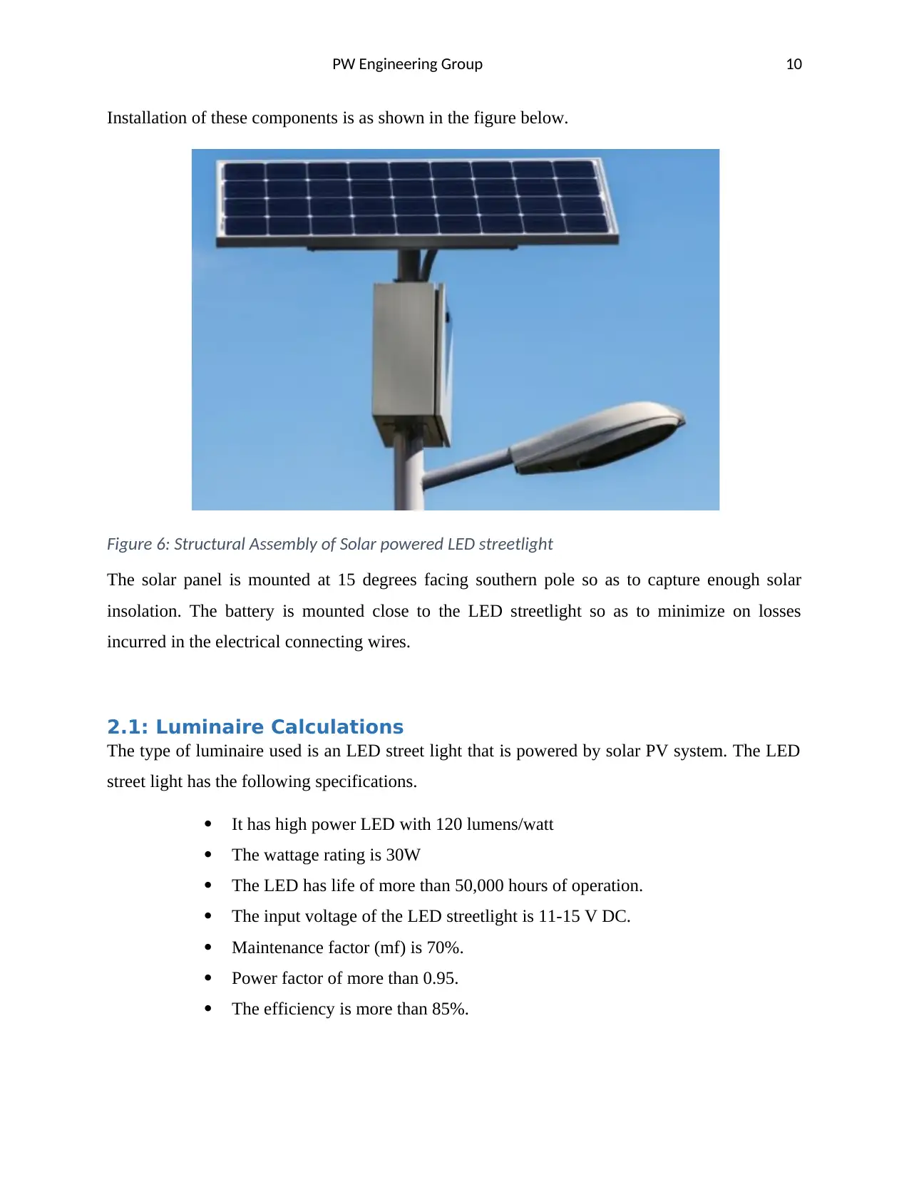
Installation of these components is as shown in the figure below.
Figure 6: Structural Assembly of Solar powered LED streetlight
The solar panel is mounted at 15 degrees facing southern pole so as to capture enough solar
insolation. The battery is mounted close to the LED streetlight so as to minimize on losses
incurred in the electrical connecting wires.
2.1: Luminaire Calculations
The type of luminaire used is an LED street light that is powered by solar PV system. The LED
street light has the following specifications.
It has high power LED with 120 lumens/watt
The wattage rating is 30W
The LED has life of more than 50,000 hours of operation.
The input voltage of the LED streetlight is 11-15 V DC.
Maintenance factor (mf) is 70%.
Power factor of more than 0.95.
The efficiency is more than 85%.
Secure Best Marks with AI Grader
Need help grading? Try our AI Grader for instant feedback on your assignments.
PW Engineering Group 11
2.1.1: Maintenance Factor.
The maintenance factor is included in the calculation to compensate for the gradual deterioration
of the illumination quality. The MF is normally given by the manufacturer. For this particular
LED streetlight, the maintenance factor is 70%. Symbolically;
mf =0.7 (1)
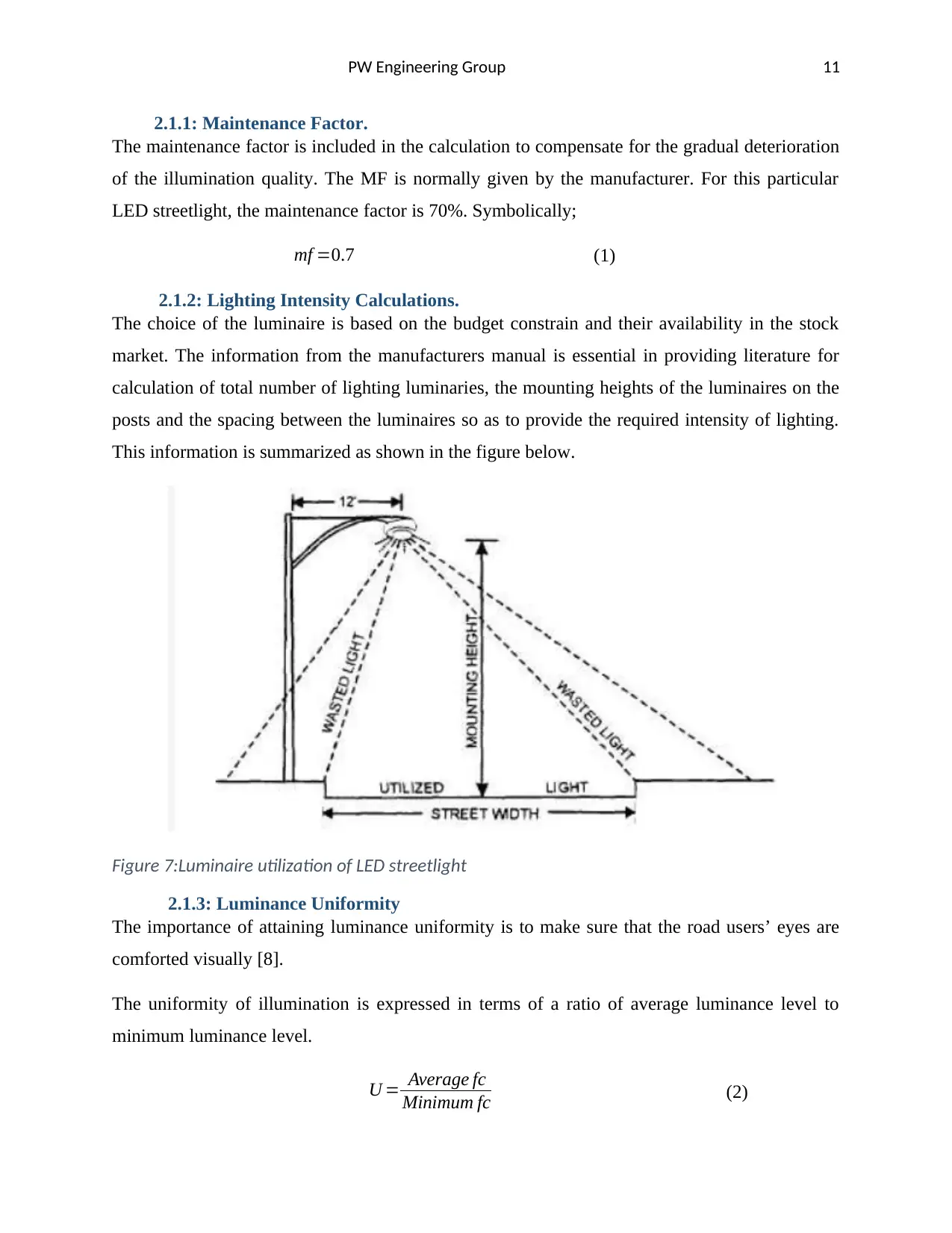
2.1.2: Lighting Intensity Calculations.
The choice of the luminaire is based on the budget constrain and their availability in the stock
market. The information from the manufacturers manual is essential in providing literature for
calculation of total number of lighting luminaries, the mounting heights of the luminaires on the
posts and the spacing between the luminaires so as to provide the required intensity of lighting.
This information is summarized as shown in the figure below.
Figure 7:Luminaire utilization of LED streetlight
2.1.3: Luminance Uniformity
The importance of attaining luminance uniformity is to make sure that the road users’ eyes are
comforted visually [8].
The uniformity of illumination is expressed in terms of a ratio of average luminance level to
minimum luminance level.
U = Average fc
Minimum fc (2)
2.1.1: Maintenance Factor.
The maintenance factor is included in the calculation to compensate for the gradual deterioration
of the illumination quality. The MF is normally given by the manufacturer. For this particular
LED streetlight, the maintenance factor is 70%. Symbolically;
mf =0.7 (1)
2.1.2: Lighting Intensity Calculations.
The choice of the luminaire is based on the budget constrain and their availability in the stock
market. The information from the manufacturers manual is essential in providing literature for
calculation of total number of lighting luminaries, the mounting heights of the luminaires on the
posts and the spacing between the luminaires so as to provide the required intensity of lighting.
This information is summarized as shown in the figure below.
Figure 7:Luminaire utilization of LED streetlight
2.1.3: Luminance Uniformity
The importance of attaining luminance uniformity is to make sure that the road users’ eyes are
comforted visually [8].
The uniformity of illumination is expressed in terms of a ratio of average luminance level to
minimum luminance level.
U = Average fc
Minimum fc (2)
PW Engineering Group 12
Where;
Average fc−¿Average luminance level.
Minimum fc−¿Minimum luminance level.
From the datasheet, the luminance uniformity is given as greater than 0.7, which is suitable for
the design. With this ratio of 0.7, the uniformity of the illumination is assured.
2.1.4: Calculating Street Light Illumination Level (E)
The recommended illumination is approximately 6.46. lumen per square meter [7].
Mathematically, the expression for finding street illumination level is given by;
Street Illumination Level∈Lux ( E )= ( Al ) (Cu ) ( mf )
( w ) ( d ) (3a)
( E ) = ( Al ) ( Cu ) ( mf )
( w ) ( d ) (3b)
Where;
E−¿ The illumination in Lux.
W −¿effective width of the road, which is 14 meters.
d .−¿ Distance between luminaries or pole to pole distance, which is 8 meters
Al−¿ Average Lumens.
mf −¿Maintenance factor given from the datasheet as 0.3.
Cu−¿ Coefficient of utilization given as 0.85.
The coefficient of utilization directly relates to the fixture type, luminaire mounting height,
effective width of the road and length of the pole arm.
But from the datasheet, high power LED with 120 lumens/watt are used. Therefore, average
lumens can be obtained from the expression below.
Al=Wattage rating(W ) × ( 120 ) { Lumens
Watts } (4)
Substituting the values in equation (4);
Where;
Average fc−¿Average luminance level.
Minimum fc−¿Minimum luminance level.
From the datasheet, the luminance uniformity is given as greater than 0.7, which is suitable for
the design. With this ratio of 0.7, the uniformity of the illumination is assured.
2.1.4: Calculating Street Light Illumination Level (E)
The recommended illumination is approximately 6.46. lumen per square meter [7].
Mathematically, the expression for finding street illumination level is given by;
Street Illumination Level∈Lux ( E )= ( Al ) (Cu ) ( mf )
( w ) ( d ) (3a)
( E ) = ( Al ) ( Cu ) ( mf )
( w ) ( d ) (3b)
Where;
E−¿ The illumination in Lux.
W −¿effective width of the road, which is 14 meters.
d .−¿ Distance between luminaries or pole to pole distance, which is 8 meters
Al−¿ Average Lumens.
mf −¿Maintenance factor given from the datasheet as 0.3.
Cu−¿ Coefficient of utilization given as 0.85.
The coefficient of utilization directly relates to the fixture type, luminaire mounting height,
effective width of the road and length of the pole arm.
But from the datasheet, high power LED with 120 lumens/watt are used. Therefore, average
lumens can be obtained from the expression below.
Al=Wattage rating(W ) × ( 120 ) { Lumens
Watts } (4)
Substituting the values in equation (4);
PW Engineering Group 13
Al=30 W × ( 120 ) Lumens
Watts (5a)
Al=3600 Lumens (5b)
Having needed parameters, substitution of the values in equation (3b) gives;
( E ) = ( 3600 ) × ( 0.85 ) × ( 0.3 )
14 m× 8 m (6a)
( E ) =¿ 8.19 Lux (6b)
2.1.5: Calculating Wattage for each street light pole luminaire
This is the actual watts of light energy that is lit on the surface of the road. Details required to
calculate watts of street light luminaire are given below.
Luminous efficacy is 120 Lumen/Watt as from the data sheet.
Therefore, the watt of each street light required is given by;
Watt of Each Street Light Luminaire= Average Lumenof Lamp
Luminous Efficacy (7)
Rewriting equation (7) using algebraic symbols;
W pol= Al
¿ (8)
Substituting the values;
W pol= 3600 Lumens
120 Lumesn/watt (9)
Simplifying equation (9);
W pol=30 Watts (10)
The figure below shows the suitable 30 Watt luminary that was chosen for the design of this
particular scheme.
Paraphrase This Document
Need a fresh take? Get an instant paraphrase of this document with our AI Paraphraser
PW Engineering Group 14
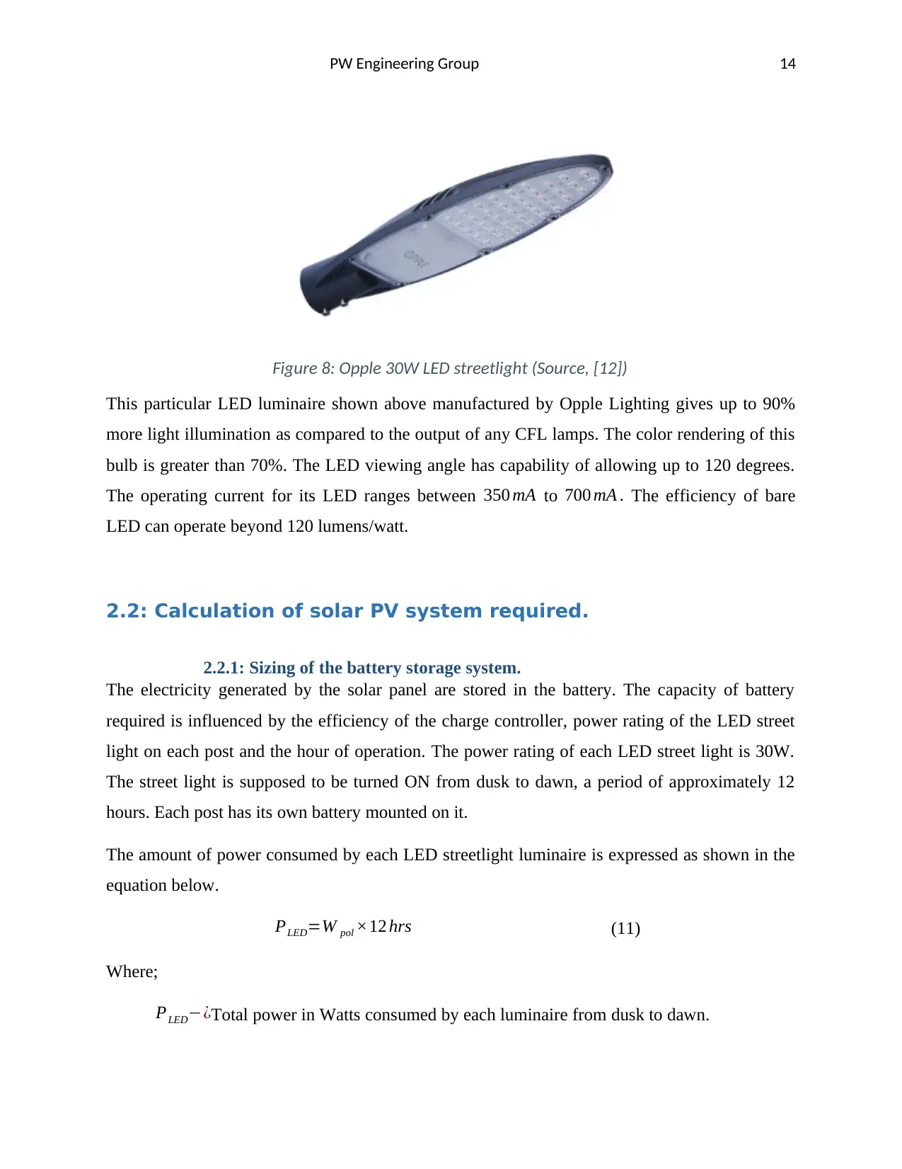
Figure 8: Opple 30W LED streetlight (Source, [12])
This particular LED luminaire shown above manufactured by Opple Lighting gives up to 90%
more light illumination as compared to the output of any CFL lamps. The color rendering of this
bulb is greater than 70%. The LED viewing angle has capability of allowing up to 120 degrees.
The operating current for its LED ranges between 350 mA to 700 mA . The efficiency of bare
LED can operate beyond 120 lumens/watt.
2.2: Calculation of solar PV system required.
2.2.1: Sizing of the battery storage system.
The electricity generated by the solar panel are stored in the battery. The capacity of battery
required is influenced by the efficiency of the charge controller, power rating of the LED street
light on each post and the hour of operation. The power rating of each LED street light is 30W.
The street light is supposed to be turned ON from dusk to dawn, a period of approximately 12
hours. Each post has its own battery mounted on it.
The amount of power consumed by each LED streetlight luminaire is expressed as shown in the
equation below.
PLED=W pol ×12 hrs (11)
Where;
PLED−¿Total power in Watts consumed by each luminaire from dusk to dawn.
PW Engineering Group 15
W pol−¿Wattage rating of each LED streetlight luminaire.
Substituting the values in equation (10), total power for each LED streetlight is;
PLED=30 W ×12 hrs (12a)
PLED=360 Wh (12b)
The efficiency of each LED streetlight as stated in the datasheet is 0.85 and the luminaire is
powered by maximum current of 700 mA . Together with efficiency of the charge controller, the
information is necessary for the calculation of capacity of the battery required by using the
expression below.
Cbat= PLED
V T
× 1
ηeff
× 1
DoD (13)
Where;
Cbat−¿Battery capacity in Ampere-hr (Ah).
V T −¿Terminal voltage of the battery which is equivalent to the rated DC voltage of the
luminaire.
ηeff −¿Effective efficiency of the power source.
DoD−¿Depth of Discharge of the battery.
Assuming that the efficiency of the controller is 98%, the effective efficiency of the power
source is given by;
ηeff =0.98 ×0.85 (14a)
ηeff =0.83
The average rated terminal voltage for the LED streetlight is;
V T =12V DC (15)
Since the batteries for this application are meant to serve longest, then imposing low DoD will
necessitate longer lifespan as desired. Therefore, the DoD was set to be 30%.
PW Engineering Group 16
DoD=30 % (16)
Substituting the values in equation (13), the capacity of the battery suitable for this application is
provided as;
Cbat= 360W
12 V × 1
0.83 × 1
0.3 Ah (16a)
Cbat=117 Ah (16b)
The approximate available capacity of the battery in the stock market is;
Cbat=120 A h (17)
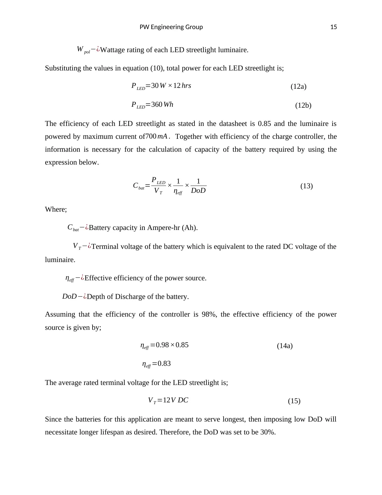
The battery preferred for this project is a 12V 120AH Lithium ion battery pack, type
1ON012120T16. This battery is shown below.
Figure 9: 12V 120AH Lithium ion battery pack (Source, [8])
This is an exclusive lithium packed battery that is ultra-compact making it suitable for this
application. The battery is rated 12V terminal voltage and the capacity is 120Ah.
2.2.2: Micro-controller based charge controller.
Charge controller as the name implies controlling the charging and discharging process of the
storage battery. During charging, electric current flows from the solar panel to the battery
through charge controller as an intermediate link. It limits excessive charging current thereby
preventing overcharging. Overvoltage as a result of overcharging could lead to compromised
battery performance or and reduced lifespan. In this application, micro-controller based charge
DoD=30 % (16)
Substituting the values in equation (13), the capacity of the battery suitable for this application is
provided as;
Cbat= 360W
12 V × 1
0.83 × 1
0.3 Ah (16a)
Cbat=117 Ah (16b)
The approximate available capacity of the battery in the stock market is;
Cbat=120 A h (17)
The battery preferred for this project is a 12V 120AH Lithium ion battery pack, type
1ON012120T16. This battery is shown below.
Figure 9: 12V 120AH Lithium ion battery pack (Source, [8])
This is an exclusive lithium packed battery that is ultra-compact making it suitable for this
application. The battery is rated 12V terminal voltage and the capacity is 120Ah.
2.2.2: Micro-controller based charge controller.
Charge controller as the name implies controlling the charging and discharging process of the
storage battery. During charging, electric current flows from the solar panel to the battery
through charge controller as an intermediate link. It limits excessive charging current thereby
preventing overcharging. Overvoltage as a result of overcharging could lead to compromised
battery performance or and reduced lifespan. In this application, micro-controller based charge
Secure Best Marks with AI Grader
Need help grading? Try our AI Grader for instant feedback on your assignments.
PW Engineering Group 17
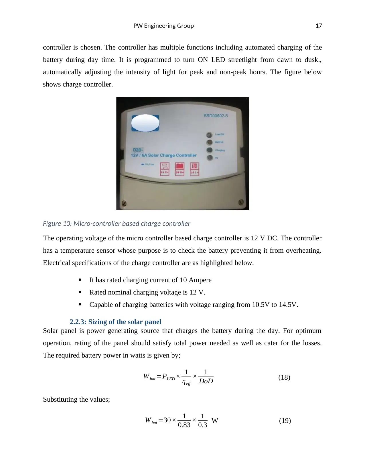
controller is chosen. The controller has multiple functions including automated charging of the
battery during day time. It is programmed to turn ON LED streetlight from dawn to dusk.,
automatically adjusting the intensity of light for peak and non-peak hours. The figure below
shows charge controller.
Figure 10: Micro-controller based charge controller
The operating voltage of the micro controller based charge controller is 12 V DC. The controller
has a temperature sensor whose purpose is to check the battery preventing it from overheating.
Electrical specifications of the charge controller are as highlighted below.
It has rated charging current of 10 Ampere
Rated nominal charging voltage is 12 V.
Capable of charging batteries with voltage ranging from 10.5V to 14.5V.
2.2.3: Sizing of the solar panel
Solar panel is power generating source that charges the battery during the day. For optimum
operation, rating of the panel should satisfy total power needed as well as cater for the losses.
The required battery power in watts is given by;
W bat =PLED × 1
ηeff
× 1
DoD (18)
Substituting the values;
W bat =30 × 1
0.83 × 1
0.3 W (19)
PW Engineering Group 18
W bat =120W
The efficiency of solar photoelectric conversion is assumed to be 96% since quality solar module
array will be preferred. Owing to the efficiency of the solar panel, the required rating of each
module is given by;
W panel= W bat
t (hr ) × 1
ηp
(20a)
Where;
W panel−¿Solar panel power rating in Watts.
ηp −¿Conversion efficiency of the solar panel, with is 96%.
t ( hr )−¿ Peak sun hours, which is approximately 4 hours in the UK.
Other environmental factors that influence amount of electricity generated by solar PV system in
the UK are also vital in sizing of the PV panel. Assuming that the environmental factor lumped
together gives a factor of 0.24. The equation governing the size of solar panel therefore becomes;
W panel= W bat
t (hr ) × 1
ηp
× 1
f E
(20b)
Where;
f E −¿Environmental factor, which is equal to 0.24.
Substituting the values in equation (20b), the required power rating of each panel is given by;
W panel= 120 W
4 hr × 1
0.96 × 1
0.24 W (21a)
W panel=13 0 W (21b)
Off-grid LD135R9W solar module from LG manufacturer chosen basing on the design
parameters.
PW Engineering Group 19
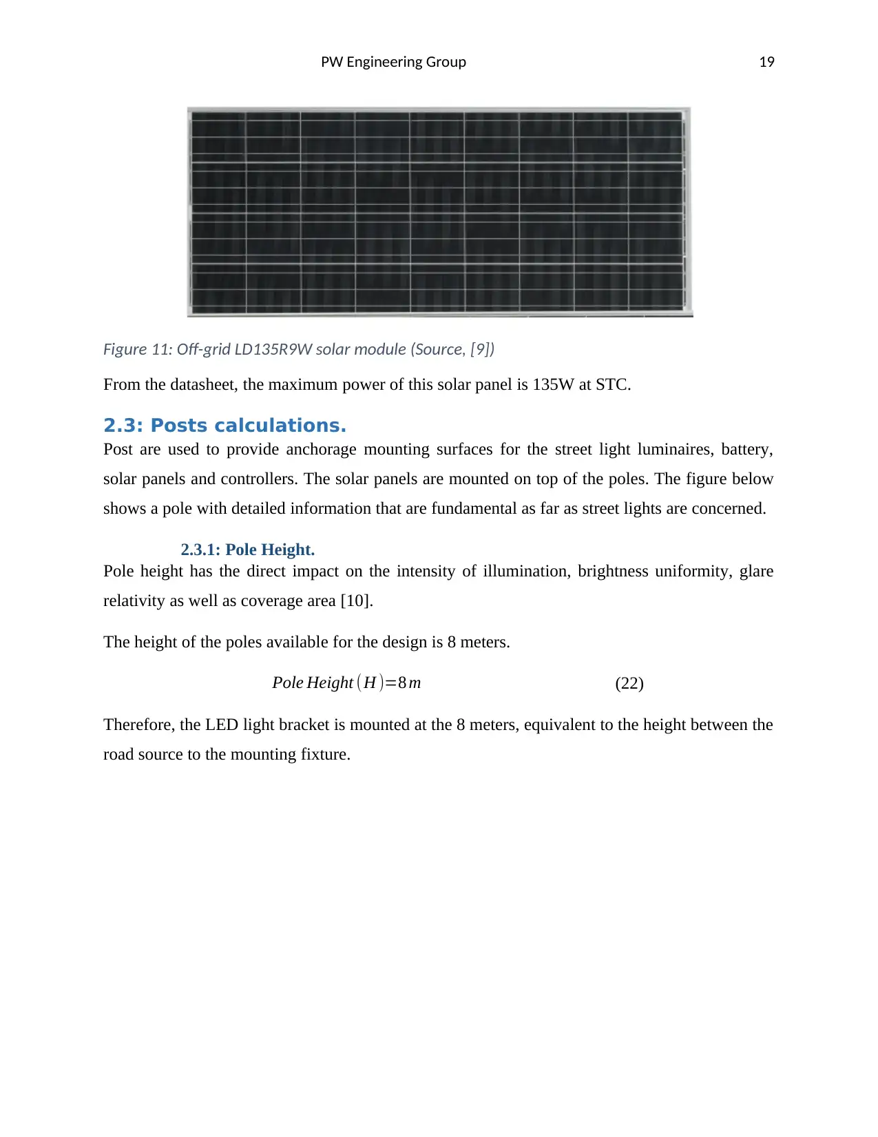
Figure 11: Off-grid LD135R9W solar module (Source, [9])
From the datasheet, the maximum power of this solar panel is 135W at STC.
2.3: Posts calculations.
Post are used to provide anchorage mounting surfaces for the street light luminaires, battery,
solar panels and controllers. The solar panels are mounted on top of the poles. The figure below
shows a pole with detailed information that are fundamental as far as street lights are concerned.
2.3.1: Pole Height.
Pole height has the direct impact on the intensity of illumination, brightness uniformity, glare
relativity as well as coverage area [10].
The height of the poles available for the design is 8 meters.
Pole Height (H )=8 m (22)
Therefore, the LED light bracket is mounted at the 8 meters, equivalent to the height between the
road source to the mounting fixture.
Paraphrase This Document
Need a fresh take? Get an instant paraphrase of this document with our AI Paraphraser
PW Engineering Group 20
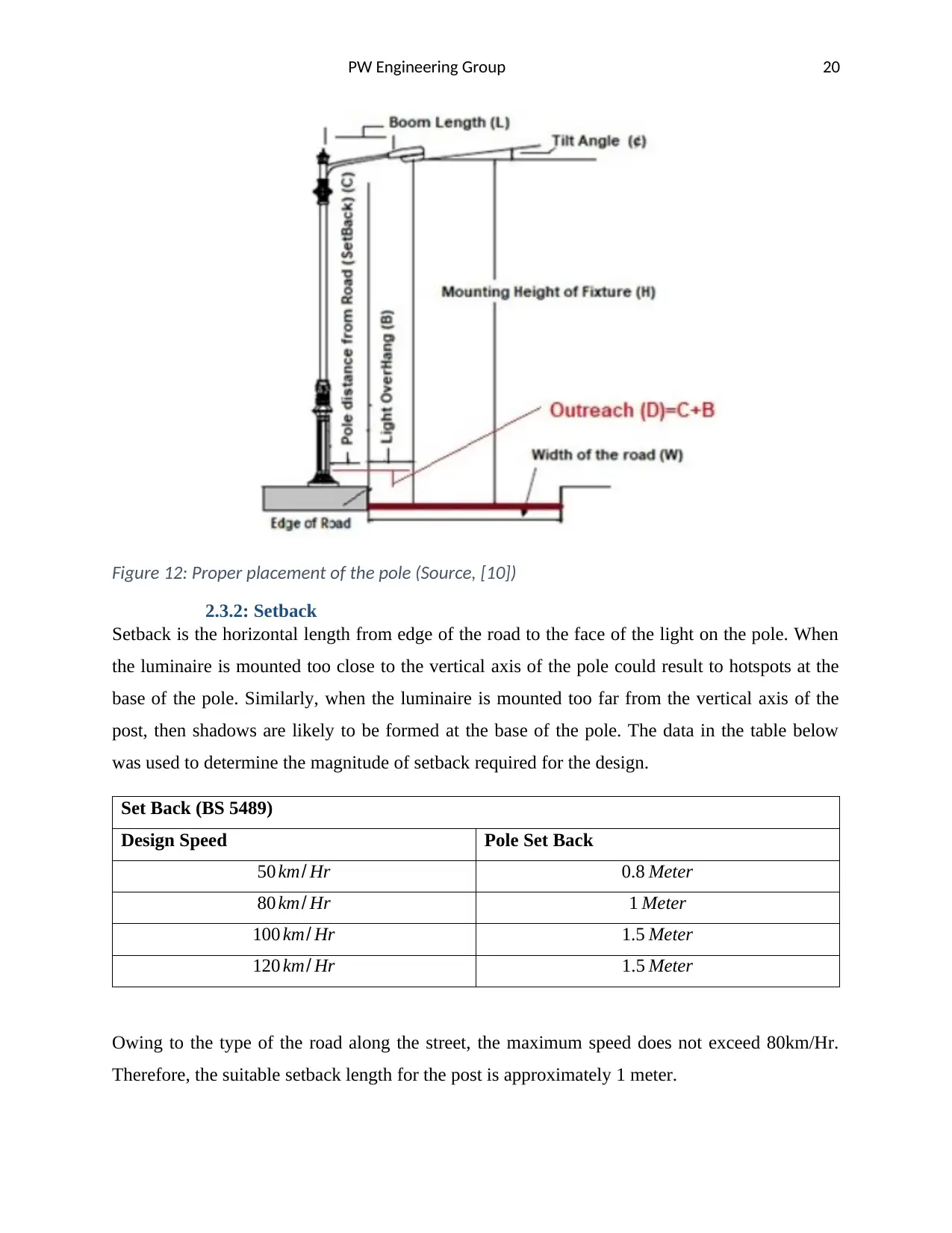
Figure 12: Proper placement of the pole (Source, [10])
2.3.2: Setback
Setback is the horizontal length from edge of the road to the face of the light on the pole. When
the luminaire is mounted too close to the vertical axis of the pole could result to hotspots at the
base of the pole. Similarly, when the luminaire is mounted too far from the vertical axis of the
post, then shadows are likely to be formed at the base of the pole. The data in the table below
was used to determine the magnitude of setback required for the design.
Set Back (BS 5489)
Design Speed Pole Set Back
50 km/ Hr 0.8 Meter
80 km/ Hr 1 Meter
100 km/ Hr 1.5 Meter
120 km/ Hr 1.5 Meter
Owing to the type of the road along the street, the maximum speed does not exceed 80km/Hr.
Therefore, the suitable setback length for the post is approximately 1 meter.
PW Engineering Group 21
Setback(C )=1 m (23)
2.3.3: Overhang
Overhang is the horizontal dimension starting from the center of a LED light mounting bracket
and the carriage way adjacent edge. The correct length of overhang improves visibility that could
have been hindered by external obstacles. In this design, the overhang was set to approximately
one fourth of the luminaire mounting height (H).
Overhang= 1
4 × ( Luminaire Mounting Height ) (24a)
The algebraic representation of equation (24a) is as shown below.
B= 1
4 × ( H ) (24b)
Substituting the height of the post;
B= 1
4 × 8 m (25)
B=2 m
2.3.4: Outreach
Outreach is basically the horizontal length between the center of the luminaire with respect to the
center of the column. The magnitude of this length depends on the aesthetic value of the
architect. In the case of this report, the outreach was found by summing up overhang and setback
as shown below.
Outreach=Overhang + Setback (26)
Using the symbolic representation as shown in the figure of the post;
D=C + B (27)
Substituting the values in equation (27);
D=1 m+2 m (28)
D=3 m
PW Engineering Group 22
2.3.5: Pole arm length.
The pole arm is used for mounting the luminaire, bringing the light closer to the roadway.
Different types of pole arms are used depending on the arm length required. Type A is used
when arm length of 2 meter or and 2.5 meter are required in the designed specification. On
contrary, type B arm is required when arm length required extends up to 3.5 meters or 4 meters
to 5 meters. Pole height dictates the type of pole arm suitable for such application. For instance,
type A is suitable for pole height up to 10 meters while type B is suitable for pole height up to 13
meters. In this design, type A is preferred since the length of the pole is 8 meters. Therefore;
Boom length ( L ) =2m (29)
L=2 m
2.3.6: Pole arm tilt angle.
The boom angle should be in a manner which hinders direct light glare shinning into the eyes of
the driver. Direct glares from the luminaire causes discomfort hence endangering judgmental
driving skills of the driver. Suitable angle of tilt is kept between 15 degrees to 30 degrees.
Tilt Angle(∅)=15o (30)
2.3.7: Pole to pole spacing
Pole to pole spacing in this context is the distance of separation between mounted luminaires
taken from the center of the road. The space to height ratio of luminaire mounting should be
capable of providing uniform longitudinal illumination of the road. With closer interval pole to
pole spacing, the scallops are eliminated by the uniformity of luminaires. However, when
factoring in the cost of the project, the spacing should be considerably large enough so as to
minimize on the number of poles required [7].
The spacing between poles are calculated to be approximately 3 times the pole height. Details of
the streetlight per pole are;
The effective width of the road (W) is 14 meter.
The pole height (H) was found to be 8 meters.
Wattage rating of each luminaire is 30 Watts
Lamp output (LL) for each is 3600 Lumen.
Lux Level required in the design is ¿) from (equation 6b)
Secure Best Marks with AI Grader
Need help grading? Try our AI Grader for instant feedback on your assignments.
PW Engineering Group 23
Coefficient of utilization factor is (Cu) 0.85
Factoring in essential parameters, the pole to pole spacing is calculated using the mathematical
formula as shown below [11]
Pole ¿ pole spacing= ( H ) ( Cu ) ( ¿ )
( E ) ( W ) (31)
Substituting the values in equation (31), distance between poles is;
Pole ¿ pole spacing= ( 8 m ) ( 0.85 ) ( 36 0 Lumen )
( 8.19 Lux ) (14 m ) (32a)
Pole ¿ pole spacing=21 m (32b)
Space height ratio is calculated as;
Space height Ratio=Pole ¿ pole spacing ¿
Height of the pole
(32)
Substituting the values;
Space height Ratio=21 m
8 m (33a)
Space height Ratio=2.625 (33b)
This ratio is less than 3, satisfying the aforementioned condition. Therefore, the pole to pole
spacing of the design is 21 meters.
2.3.7: Battery installation box.
The battery is secured onto the post using bolted battery box. The battery box houses the battery
shielding it from harsh external conditions such as high temperature and humid condition. The
size of the battery is determined by the size of the battery. The battery box for this project is as
shown in the figure below.
PW Engineering Group 24
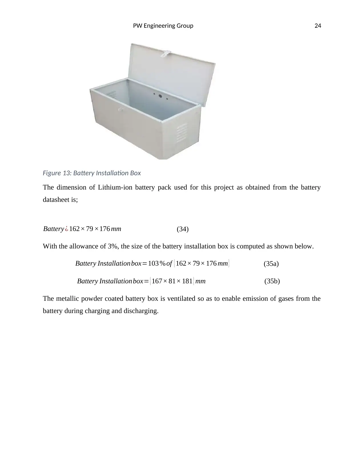
Figure 13: Battery Installation Box
The dimension of Lithium-ion battery pack used for this project as obtained from the battery
datasheet is;
Battery ¿ 162× 79 ×176 mm (34)
With the allowance of 3%, the size of the battery installation box is computed as shown below.
Battery Installationbox=103 % of { 162× 79× 176 mm } (35a)
Battery Installationbox= { 167× 81× 181 } mm (35b)
The metallic powder coated battery box is ventilated so as to enable emission of gases from the
battery during charging and discharging.
PW Engineering Group 25
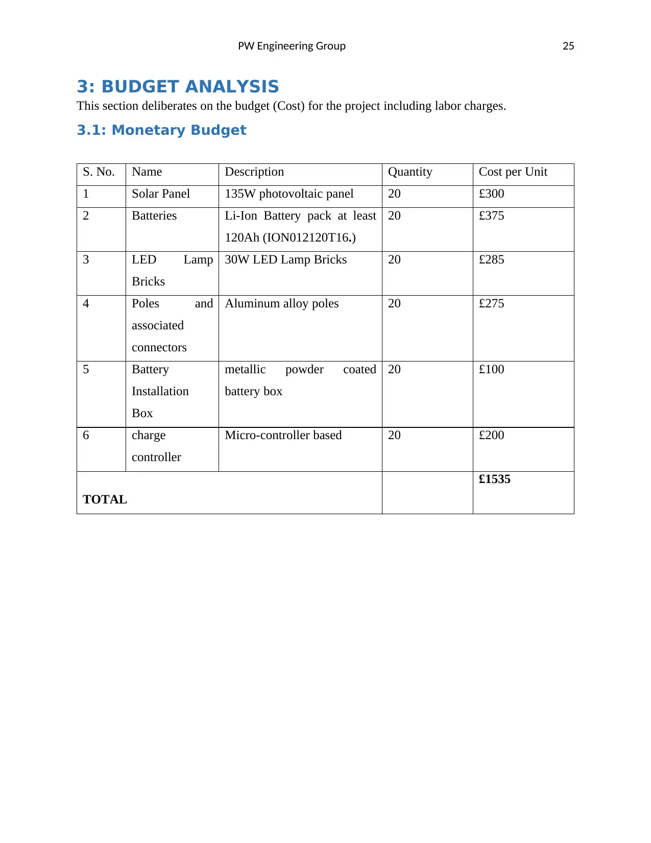
3: BUDGET ANALYSIS
This section deliberates on the budget (Cost) for the project including labor charges.
3.1: Monetary Budget
S. No. Name Description Quantity Cost per Unit
1 Solar Panel 135W photovoltaic panel 20 £300
2 Batteries Li-Ion Battery pack at least
120Ah (ION012120T16.)
20 £375
3 LED Lamp
Bricks
30W LED Lamp Bricks 20 £285
4 Poles and
associated
connectors
Aluminum alloy poles 20 £275
5 Battery
Installation
Box
metallic powder coated
battery box
20 £100
6 charge
controller
Micro-controller based 20 £200
TOTAL
£1535
Paraphrase This Document
Need a fresh take? Get an instant paraphrase of this document with our AI Paraphraser
PW Engineering Group 26
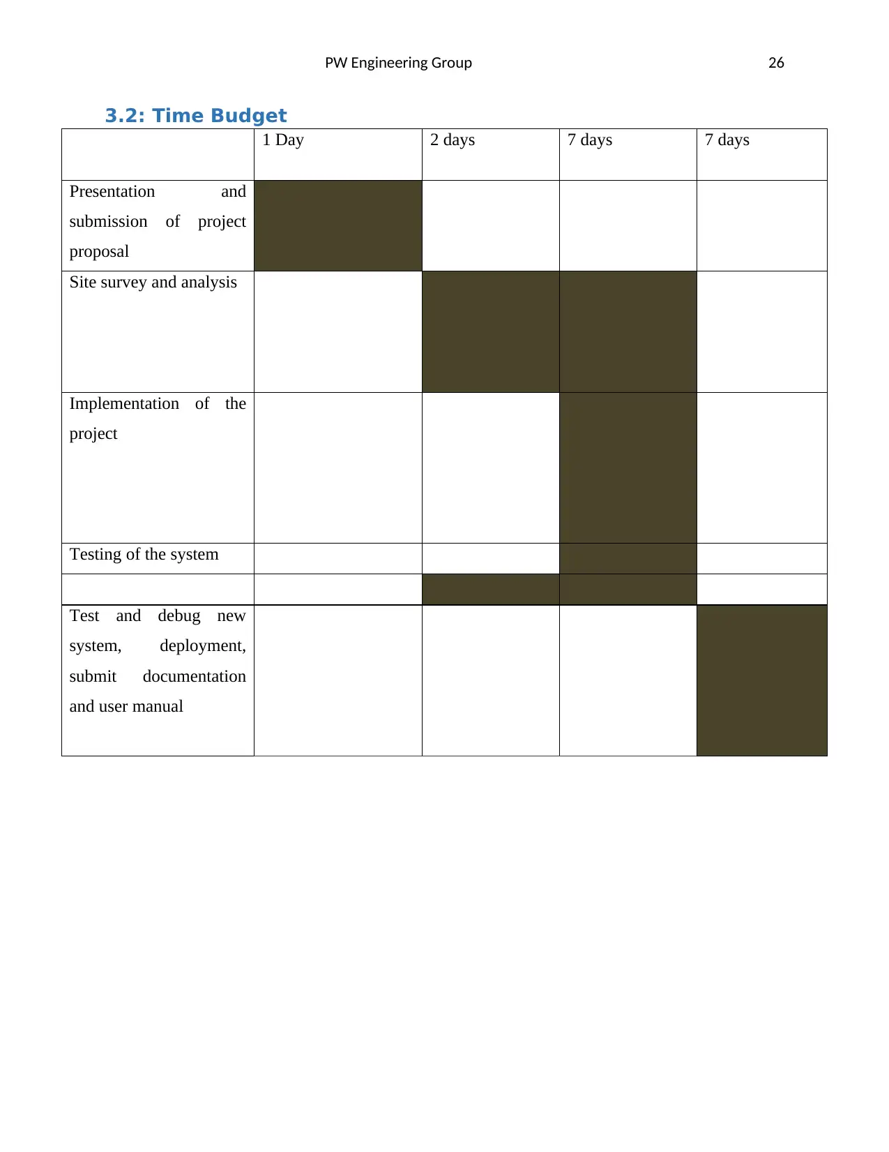
3.2: Time Budget
1 Day 2 days 7 days 7 days
Presentation and
submission of project
proposal
Site survey and analysis
Implementation of the
project
Testing of the system
Test and debug new
system, deployment,
submit documentation
and user manual
3.2: Time Budget
1 Day 2 days 7 days 7 days
Presentation and
submission of project
proposal
Site survey and analysis
Implementation of the
project
Testing of the system
Test and debug new
system, deployment,
submit documentation
and user manual

PW Engineering Group 27
4: CONCLUSION
The design of the solar powered LED streetlight has been implemented according to the
proposal. The design has looked into essential factors for the proper functional as well as cost
effectiveness of equipment and components at various stages. However, the specified
components including respective manufacturers can be substituted with other counterparts basing
on the cost and availability in the stock market but without interfering with the designed quality
of the scheme. Timeline of the project implementation has also been stated, subject to correction
depending on the cooperation of the various stakeholders involved in this project. Completion of
the projects comes with extra maintenance costs. The maintenance cost has to be paid
consistently so that the lighting goes on smoothly.

PW Engineering Group 28
REFERENCES.
[1] Fox, S. (2018). How Does Heat Affect Solar Panel Efficiencies? [Online]. Available:
https://www.civicsolar.com/article/how-does-heat-affect-solar-panel-efficiencies. [Accessed: 03-
Apr- 2020].
[2] World Weather Online, W. (2019). Preston Monthly Climate Averages. [Online]. Available:
https://www.worldweatheronline.com/preston-weather-averages/lancashire/gb.aspx. [Accessed:
03- Apr- 2020].
[3] SEPCO. (2019). Performance and Maintenance of Solar Panels in Cold Climates. [Online].
Available: https://www.sepco-solarlighting.com/blog/performance-and-maintenance-of-solar-
panels-in-cold-climates. [Accessed: 03- Apr- 2020].
[4] Maecel Suri, Tomas Cebecauer, Artur Skozek, Ronald Marais, Crescent Mushwana, Josh
Reinecke & Riaan Meyer. (2019). Cloud Cover Impact On Photovoltaic Power Production in
South Africa. [Online]. Available:
https://solargis2-web-assets.s3.eu-west-1.amazonaws.com/public/publication/2014/7e83f59297/
Suri-et-al-SASEC2014-Cloud-cover-impact-on-PV-power-production-in-South-Africa.pdf.
[Accessed: 03- Apr- 2020].
[5] Gaisma. (2019). Preston, United Kingdom - Sunrise, sunset, dawn and dusk times for the
whole year. [Online]. Available: https://www.gaisma.com/en/location/preston.html. [Accessed:
03- Apr- 2020].
[6] Viridiansolar.co.uk. (2019). Tilt and Orientation and Solar Energy, 2019 [Online]. Available:
http://www.viridiansolar.co.uk/resources-1-3-tilt-and-orientation.html [Accessed: 03- Apr-2020].
Secure Best Marks with AI Grader
Need help grading? Try our AI Grader for instant feedback on your assignments.
PW Engineering Group 29
[7] J. Parmar, "How to Design efficient Street lighting-(Part-1)", Electrical Notes & Articles,
2019. [Online]. Available: https://electricalnotes.wordpress.com/2019/04/24/how-to-design-
efficient-street-lighting-part-1/. [Accessed: 03- Apr- 2020].
[8]"Lithium-ion-battery Datasheet", Erun.ch, 2017. [Online]. Available:
https://www.erun.ch/index_htm_files/ION012120T16%20V%20E.pdf. [Accessed: 03- Apr-
2020].
[9]"LD135R9W solar panel Datasheet", Solarselections.co.uk, 2020. [Online]. Available:
http://www.solarselections.co.uk/blog/wp-content/uploads/2012/09/LG-Solar-Panels-Off-grid-
Spec-Sheet1.pdf. [Accessed: 03- Apr- 2020].
[10]"Mn/Dot Roadway Lighting Design Manual", Dot.state.mn.us, 2010. [Online]. Available:
http://www.dot.state.mn.us/trafficeng/lighting/2010_Roadway
%20Lighting_Design_Manual2.pdf. [Accessed: 03- Apr- 2020].
[11]"EngineeringDiscoveries.com", Engineering Discoveries, 2020. [Online]. Available:
https://engineeringdiscoveries.com/2019/12/29/how-to-calculate-no-of-street-light-poles/.
[Accessed: 03- Apr- 2020].
[12]"LEDStreetlight 20W-4000K-SE | OPPLE Lighting", Eu.opple.com, 2020. [Online].
Available: https://eu.opple.com/en/product/led-luminaires/led-road-streetlight/led-streetlight/
ledstreetlight-20w-4000k-se. [Accessed: 03- Apr- 2020].

PW Engineering Group 30
APPENDIX 1.
Lithium-ion battery pack; ION012120T16.
The battery has inbuilt fire protection system. Technical data of the battery is summarized in the
table below.
TECHNICAL DATA
Voltage 10.8V nominal 8.8-12.6V
Capacity 120Ah / 1266wh
Charging/Discharging current 40 A / 40 A
Fault current limiter Yes, electronic
Balancing cells Yes
Overcharge protection Yes
Deep discharge protection Yes
Operating temperature charge 10 to 45 degrees Celsius
Operating temperature discharge -20 to 60 degrees Celsius

PW Engineering Group 31
Storage Conditions -20 to 40 degrees Celsius
SOC measuring Yes
SOC display OLED Display
Connector Modular
Digital connection Yes
DimensionL × B× H 162 ×79 ×176 mm
Weight 6.4kg
Warranty Perion 2 years/ 1000 cycles
APPENDIX 2.
Off-grid LD135R9W LG solar panel.
Technical data of the solar panel, manufactured by LG company is as shown in the table below.
TECHNICAL DATA
Maximum power at STC(Pmax) 135W
MPP voltage (Vmpp) 17.25 V
MPP current (Impp) 21.80
Short circuit current (Isc) 8.41
Module efficiency (%) 13.7
Operating temperature -40 to 90 degrees Celsius
Maximum System Voltage 1000 V
Maximum series fuse rating (V) 15 V
Cell type Multicrystalline
Dimension (L ×W × H ) 1474 × 668× 42 mm
Weight 12.4 kg
Paraphrase This Document
Need a fresh take? Get an instant paraphrase of this document with our AI Paraphraser
PW Engineering Group 32
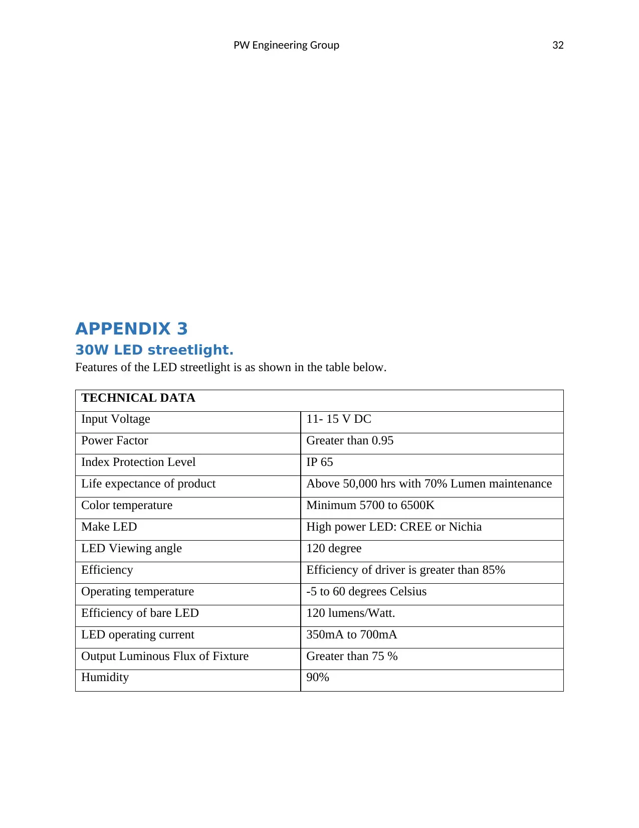
APPENDIX 3
30W LED streetlight.
Features of the LED streetlight is as shown in the table below.
TECHNICAL DATA
Input Voltage 11- 15 V DC
Power Factor Greater than 0.95
Index Protection Level IP 65
Life expectance of product Above 50,000 hrs with 70% Lumen maintenance
Color temperature Minimum 5700 to 6500K
Make LED High power LED: CREE or Nichia
LED Viewing angle 120 degree
Efficiency Efficiency of driver is greater than 85%
Operating temperature -5 to 60 degrees Celsius
Efficiency of bare LED 120 lumens/Watt.
LED operating current 350mA to 700mA
Output Luminous Flux of Fixture Greater than 75 %
Humidity 90%
PW Engineering Group 33
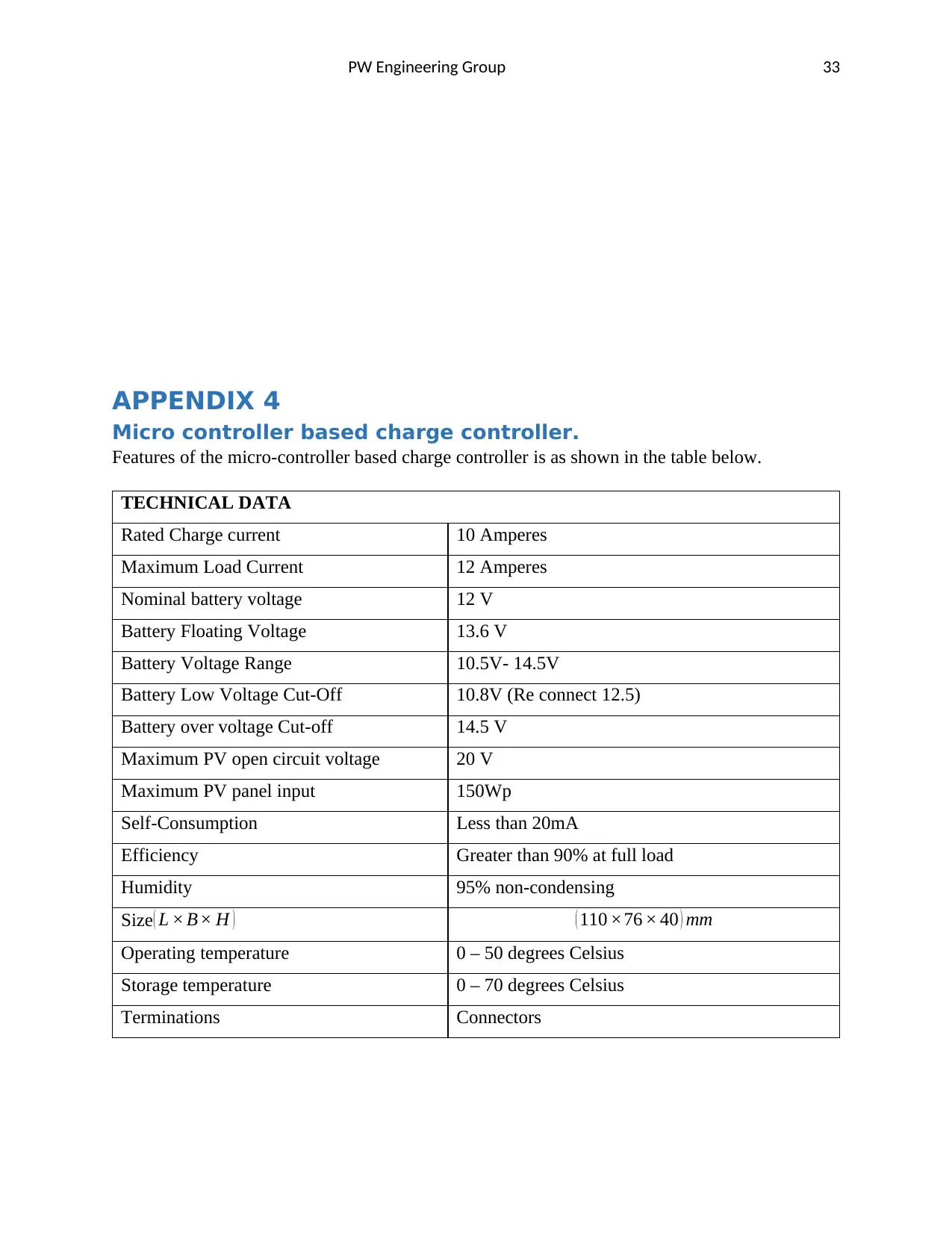
APPENDIX 4
Micro controller based charge controller.
Features of the micro-controller based charge controller is as shown in the table below.
TECHNICAL DATA
Rated Charge current 10 Amperes
Maximum Load Current 12 Amperes
Nominal battery voltage 12 V
Battery Floating Voltage 13.6 V
Battery Voltage Range 10.5V- 14.5V
Battery Low Voltage Cut-Off 10.8V (Re connect 12.5)
Battery over voltage Cut-off 14.5 V
Maximum PV open circuit voltage 20 V
Maximum PV panel input 150Wp
Self-Consumption Less than 20mA
Efficiency Greater than 90% at full load
Humidity 95% non-condensing
Size( L × B× H ) ( 110 ×76 × 40 ) mm
Operating temperature 0 – 50 degrees Celsius
Storage temperature 0 – 70 degrees Celsius
Terminations Connectors

PW Engineering Group 34
1 out of 34
Related Documents

Your All-in-One AI-Powered Toolkit for Academic Success.
+13062052269
info@desklib.com
Available 24*7 on WhatsApp / Email
![[object Object]](/_next/static/media/star-bottom.7253800d.svg)
Unlock your academic potential
© 2024 | Zucol Services PVT LTD | All rights reserved.