Analysis of Linear Dynamic Systems: Control Systems Homework
VerifiedAdded on 2023/01/23
|6
|1767
|52
Homework Assignment
AI Summary
This homework assignment analyzes the characteristics of linear dynamic systems, focusing on second-order systems and their responses. It examines a continuous-time transfer function, calculating natural frequency, damping ratio, and pole values to determine system stability and response characteristics like overshoot and peak time. The solution explores the effects of varying parameters (p and z) on system behavior, including overdamped, critically damped, and underdamped responses, as well as the impact of negative parameter values. Step responses are analyzed, and the relationship between parameters and performance metrics like overshoot and peak time are discussed. The assignment also considers the influence of zeros on system behavior and non-minimum phase systems.

Q. 2. 1. 1.
2.924
Transfer function, G = ---------------------
s^2 + 1.611 s + 2.924
The above transfer function is of a second order dynamic system. It is a continuous time
transfer function with having a natural frequency of 1.710 rad per second and damping ratio
of 0.471. It have pole values of (-0.8054 + 1.5084i) and (-0.8054 - 1.5084i). The poles are
present in the negative real axis with having an imaginary part. The system is a stable
Underdamped system. It has an overshoot of 16.7% and peak time, tp as 2.06 Sec.
Q. 2. 1. 2.
The response is Underdamped response of a stable system. It has a rise time of 0.92 Sec and
setting time of 4.84 Sec. The peak amplitude of the response curve is 1.19. The steady state
achieved with amplitude of 1.
Step Response
Time (seconds)
Amplitude
0 1 2 3 4 5 6 7
0
0.2
0.4
0.6
0.8
1
1.2
1.4
System: G
Peak amplitude: 1.19
Overshoot (%): 18.7
At time (seconds): 2.06
Q. 2. 2. 1.
Transfer Function (G2) Poles Overshoots
(Mp) %
Peak
Time (tp)
(Seconds)
P
0.5848
--------------------------
s^3 + 1.811 s^2 + 3.246 s + 0.5848
-0.8054 + 1.5084i
-0.8054 - 1.5084i
-0.2000 + 0.0000i
0 0 0.2
1.462
--------------------------------
s^3 + 2.111 s^2 + 3.73 s + 1.462
-0.8054 + 1.5084i
-0.8054 - 1.5084i
-0.5000 + 0.0000i
0 0 0.5
Paraphrase This Document
Need a fresh take? Get an instant paraphrase of this document with our AI Paraphraser
2.924
---------------------------------
s^3 + 2.611 s^2 + 4.535 s + 2.924
-0.8054 + 1.5084i
-0.8054 - 1.5084i
-1.0000 + 0.0000i
0.592 3.37 1.0
8.772
---------------------------------
s^3 + 4.611 s^2 + 7.757 s + 8.772
-3.0000 + 0.0000i
-0.8054 + 1.5084i
-0.8054 - 1.5084i
15.2 2.49 3.0
29.24
---------------------------------
s^3 + 11.61 s^2 + 19.03 s + 29.24
-10.0000 + 0.0000i
-0.8054 + 1.5084i
-0.8054 - 1.5084i
18.4 2.17 10
2924
------------------------------
s^3 + 1002 s^2 + 1614 s + 2924
1.0e+03 *
-1.0000 + 0.0000i
-0.0008 + 0.0015i
-0.0008 - 0.0015i
18.7 2.06 1000
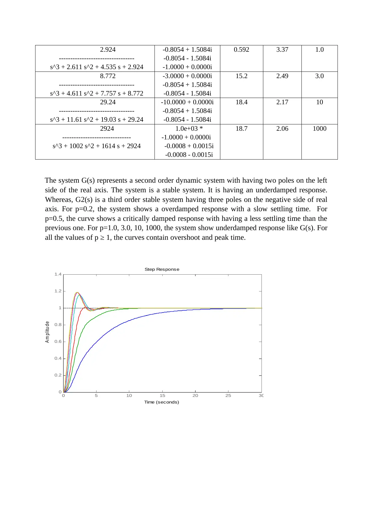
The system G(s) represents a second order dynamic system with having two poles on the left
side of the real axis. The system is a stable system. It is having an underdamped response.
Whereas, G2(s) is a third order stable system having three poles on the negative side of real
axis. For p=0.2, the system shows a overdamped response with a slow settling time. For
p=0.5, the curve shows a critically damped response with having a less settling time than the
previous one. For p=1.0, 3.0, 10, 1000, the system show underdamped response like G(s). For
all the values of p ≥ 1, the curves contain overshoot and peak time.
0 5 10 15 20 25 30
0
0.2
0.4
0.6
0.8
1
1.2
1.4
Step Response
Time (seconds)
A m p litu d e
---------------------------------
s^3 + 2.611 s^2 + 4.535 s + 2.924
-0.8054 + 1.5084i
-0.8054 - 1.5084i
-1.0000 + 0.0000i
0.592 3.37 1.0
8.772
---------------------------------
s^3 + 4.611 s^2 + 7.757 s + 8.772
-3.0000 + 0.0000i
-0.8054 + 1.5084i
-0.8054 - 1.5084i
15.2 2.49 3.0
29.24
---------------------------------
s^3 + 11.61 s^2 + 19.03 s + 29.24
-10.0000 + 0.0000i
-0.8054 + 1.5084i
-0.8054 - 1.5084i
18.4 2.17 10
2924
------------------------------
s^3 + 1002 s^2 + 1614 s + 2924
1.0e+03 *
-1.0000 + 0.0000i
-0.0008 + 0.0015i
-0.0008 - 0.0015i
18.7 2.06 1000
The system G(s) represents a second order dynamic system with having two poles on the left
side of the real axis. The system is a stable system. It is having an underdamped response.
Whereas, G2(s) is a third order stable system having three poles on the negative side of real
axis. For p=0.2, the system shows a overdamped response with a slow settling time. For
p=0.5, the curve shows a critically damped response with having a less settling time than the
previous one. For p=1.0, 3.0, 10, 1000, the system show underdamped response like G(s). For
all the values of p ≥ 1, the curves contain overshoot and peak time.
0 5 10 15 20 25 30
0
0.2
0.4
0.6
0.8
1
1.2
1.4
Step Response
Time (seconds)
A m p litu d e
Q. 2. 2. 2.
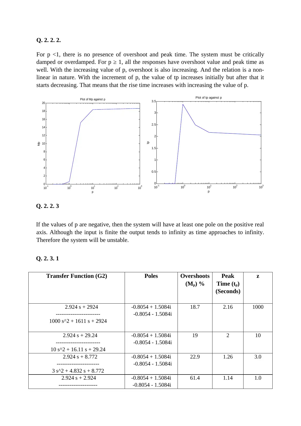
For p <1, there is no presence of overshoot and peak time. The system must be critically
damped or overdamped. For p ≥ 1, all the responses have overshoot value and peak time as
well. With the increasing value of p, overshoot is also increasing. And the relation is a non-
linear in nature. With the increment of p, the value of tp increases initially but after that it
starts decreasing. That means that the rise time increases with increasing the value of p.
10
-1 10
0 10
1 10
2 10
3
0
2
4
6
8
10
12
14
16
18
20
Plot of Mp against p
p
Mp
10-1 100 101 102 103
0
0.5
1
1.5
2
2.5
3
3.5
Plot of tp against p
p
tp
Q. 2. 2. 3
If the values of p are negative, then the system will have at least one pole on the positive real
axis. Although the input is finite the output tends to infinity as time approaches to infinity.
Therefore the system will be unstable.
Q. 2. 3. 1
Transfer Function (G2) Poles Overshoots
(Mp) %
Peak
Time (tp)
(Seconds)
z
2.924 s + 2924
------------------------
1000 s^2 + 1611 s + 2924
-0.8054 + 1.5084i
-0.8054 - 1.5084i
18.7 2.16 1000
2.924 s + 29.24
------------------------
10 s^2 + 16.11 s + 29.24
-0.8054 + 1.5084i
-0.8054 - 1.5084i
19 2 10
2.924 s + 8.772
-----------------------
3 s^2 + 4.832 s + 8.772
-0.8054 + 1.5084i
-0.8054 - 1.5084i
22.9 1.26 3.0
2.924 s + 2.924
---------------------
-0.8054 + 1.5084i
-0.8054 - 1.5084i
61.4 1.14 1.0
⊘ This is a preview!⊘
Do you want full access?
Subscribe today to unlock all pages.

Trusted by 1+ million students worldwide
s^2 + 1.611 s + 2.924
2.924 s + 1.462
--------------------------
0.5 s^2 + 0.8054 s + 1.462
-0.8054 + 1.5084i
-0.8054 - 1.5084i
148 0.915 0.5
2.924 s + 0.5848
---------------------------
0.2 s^2 + 0.3222 s + 0.5848
-0.8054 + 1.5084i
-0.8054 - 1.5084i
431 0.8 0.2
-2.924 s + 1.462
--------------------------
0.5 s^2 + 0.8054 s + 1.462
-0.8054 + 1.5084i
-0.8054 - 1.5084i
(-) 47.5 0.572 -0.5
-2.924 s + 14.62
-----------------------
5 s^2 + 8.054 s + 14.62
-0.8054 + 1.5084i
-0.8054 - 1.5084i
19.6 2.23 -5
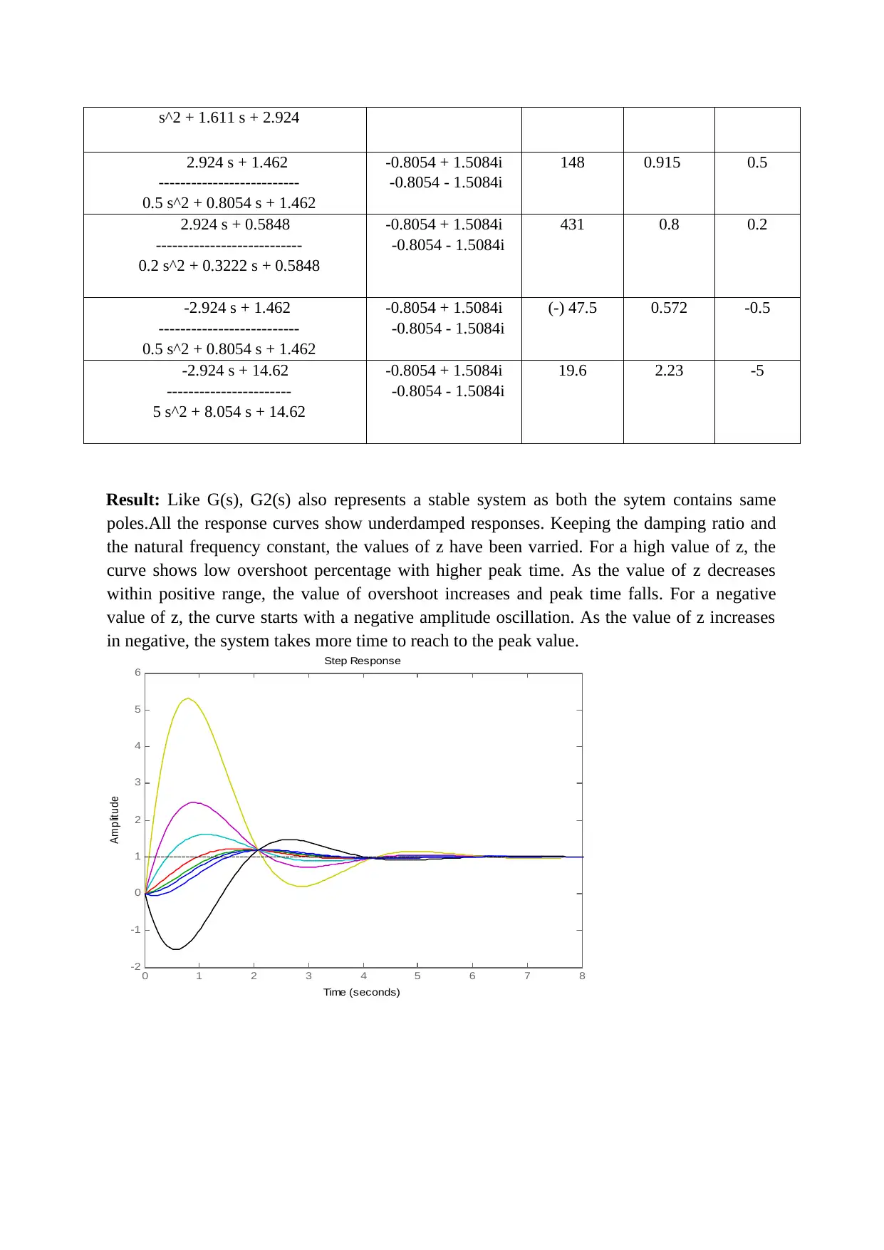
Result: Like G(s), G2(s) also represents a stable system as both the sytem contains same
poles.All the response curves show underdamped responses. Keeping the damping ratio and
the natural frequency constant, the values of z have been varried. For a high value of z, the
curve shows low overshoot percentage with higher peak time. As the value of z decreases
within positive range, the value of overshoot increases and peak time falls. For a negative
value of z, the curve starts with a negative amplitude oscillation. As the value of z increases
in negative, the system takes more time to reach to the peak value.
0 1 2 3 4 5 6 7 8
-2
-1
0
1
2
3
4
5
6
Step Response
Time (seconds)
Amplitude
Paraphrase This Document
Need a fresh take? Get an instant paraphrase of this document with our AI Paraphraser
Q. 2. 3. 2
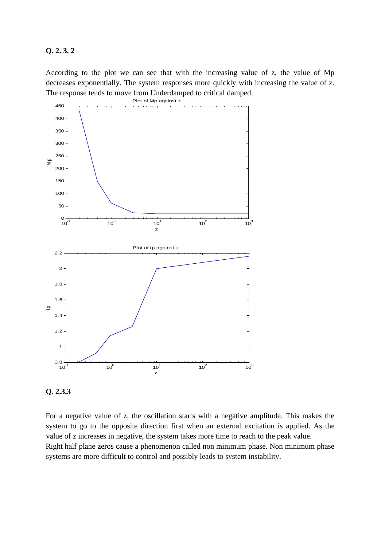
According to the plot we can see that with the increasing value of z, the value of Mp
decreases exponentially. The system responses more quickly with increasing the value of z.
The response tends to move from Underdamped to critical damped.
10
-1 10
0 10
1 10
2 10
3
0
50
100
150
200
250
300
350
400
450
Plot of Mp against z
z
M p
10
-1 10
0 10
1 10
2 10
3
0.8
1
1.2
1.4
1.6
1.8
2
2.2
Plot of tp against z
z
t p
Q. 2.3.3
For a negative value of z, the oscillation starts with a negative amplitude. This makes the
system to go to the opposite direction first when an external excitation is applied. As the
value of z increases in negative, the system takes more time to reach to the peak value.
Right half plane zeros cause a phenomenon called non minimum phase. Non minimum phase
systems are more difficult to control and possibly leads to system instability.
Q. 2. 4. 1
Transfer Function Z p Comments
1.462 s + 0.731
-------------------------------------
0.5 s^3 + 1.055 s^2 + 1.865 s + 0.731
0.5 0.5 Third order stable
system
29.24 s + 14.62
-------------------------------------
0.5 s^3 + 5.805 s^2 + 9.516 s + 14.62
0.5 10 Third order stable
system
1.462 s + 14.62
-----------------------------------
10 s^3 + 21.11 s^2 + 37.3 s + 14.62
10 0.5 Third order stable
system
29.24 s + 292.4
------------------------------------
10 s^3 + 116.1 s^2 + 190.3 s + 292.4
10 10 Third order stable
system
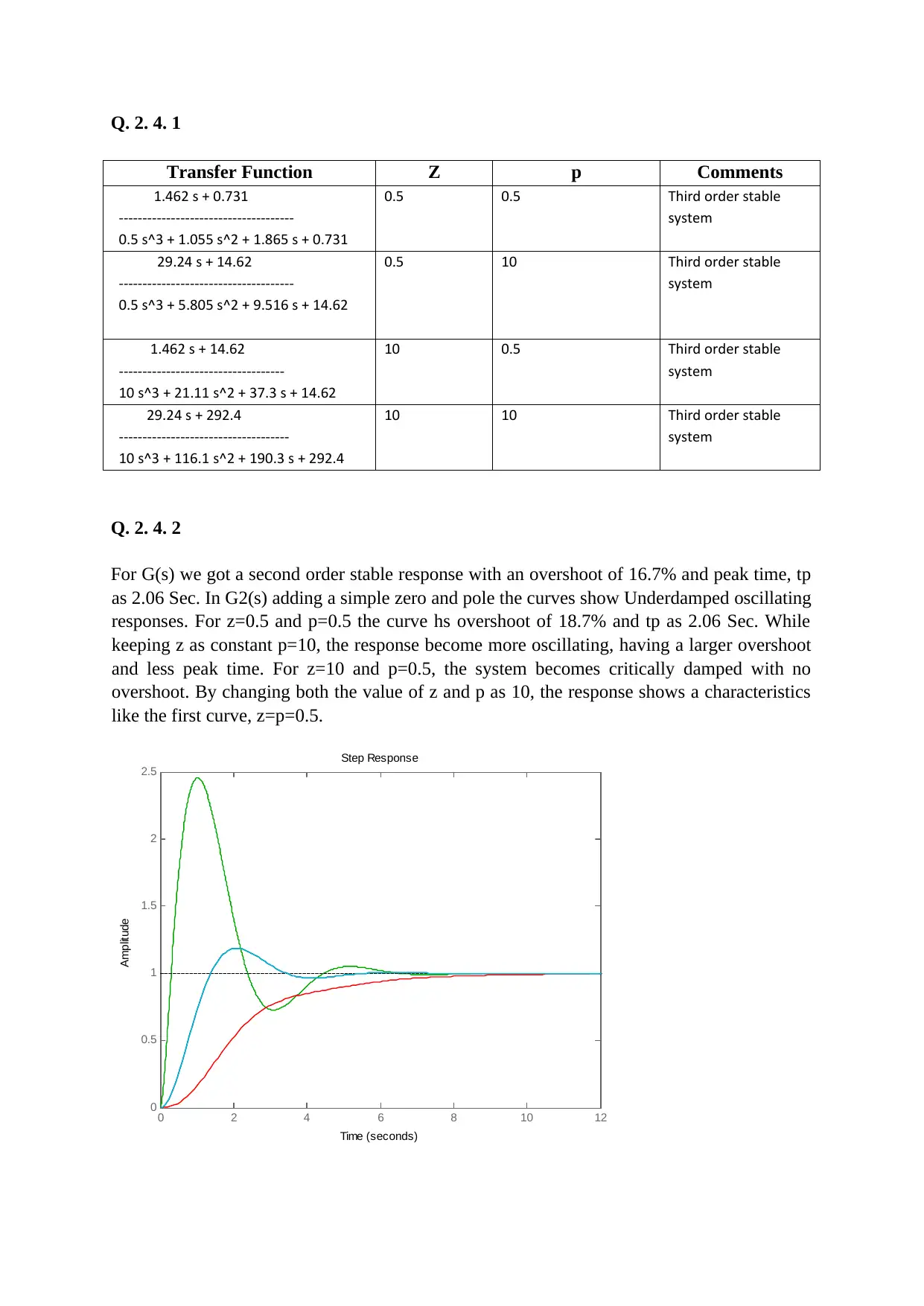
Q. 2. 4. 2
For G(s) we got a second order stable response with an overshoot of 16.7% and peak time, tp
as 2.06 Sec. In G2(s) adding a simple zero and pole the curves show Underdamped oscillating
responses. For z=0.5 and p=0.5 the curve hs overshoot of 18.7% and tp as 2.06 Sec. While
keeping z as constant p=10, the response become more oscillating, having a larger overshoot
and less peak time. For z=10 and p=0.5, the system becomes critically damped with no
overshoot. By changing both the value of z and p as 10, the response shows a characteristics
like the first curve, z=p=0.5.
0 2 4 6 8 10 12
0
0.5
1
1.5
2
2.5
Step Response
Time (seconds)
Amplitude
⊘ This is a preview!⊘
Do you want full access?
Subscribe today to unlock all pages.

Trusted by 1+ million students worldwide
1 out of 6
Related Documents
Your All-in-One AI-Powered Toolkit for Academic Success.
+13062052269
info@desklib.com
Available 24*7 on WhatsApp / Email
![[object Object]](/_next/static/media/star-bottom.7253800d.svg)
Unlock your academic potential
Copyright © 2020–2025 A2Z Services. All Rights Reserved. Developed and managed by ZUCOL.


