Communication Process in Pizza Delivery

Verified

Added on  2023/02/01

|8
|885
|36
AI Summary
This document explains the communication process involved in pizza delivery, starting from the order placement by the host to the delivery of the pizza. It describes how information is transferred between the host, pizza shop, clerk, cook, and delivery person. The document provides insights into the steps involved in completing a pizza order.

Contribute Materials

Your contribution can guide someone’s learning journey. Share your documents today.
Document Page
Q1.
Hosts receives order from guest for a Pizza. Host takes the message and uses telephone to put
message on medium. The telephone at the Pizza shop receives message and forwards it to Clerk.
This message transfer happens a few times between both parties. Once all information is
transferred, the connection over medium is terminated. The Pizza clerk transfers information to
the cook. Cook bakes the Pizza and calls the delivery Person. The parcel is transported to the
host address and order is completed.
Q2.
Suppose French Pm initiates conversation. Then he would frame a message in French and
forward to his translator. The translator would receive the message and translate it to English.
The message is then relayed to translator on other side via Telephone. Telephone on both sides
are connected by a medium that helps transfer signals on both sides and decodes them in to audio
signals. The message is received by the Chinese PM’s translator who converts the received
English message into Chinese. The translator then forwards the message from French PM to his
Chinese PM in Chinese. The process is repeated when Chinese PM sends message to French PM.
Q3.
Amplitude:
Frequency
Time
Period
Phase
Wave form A Wave form B Wave form C
15 4 7.5
0.33 0.155 0.40
3 6.5 2.5
0 0 90

Secure Best Marks with AI Grader

Need help grading? Try our AI Grader for instant feedback on your assignments.
Document Page
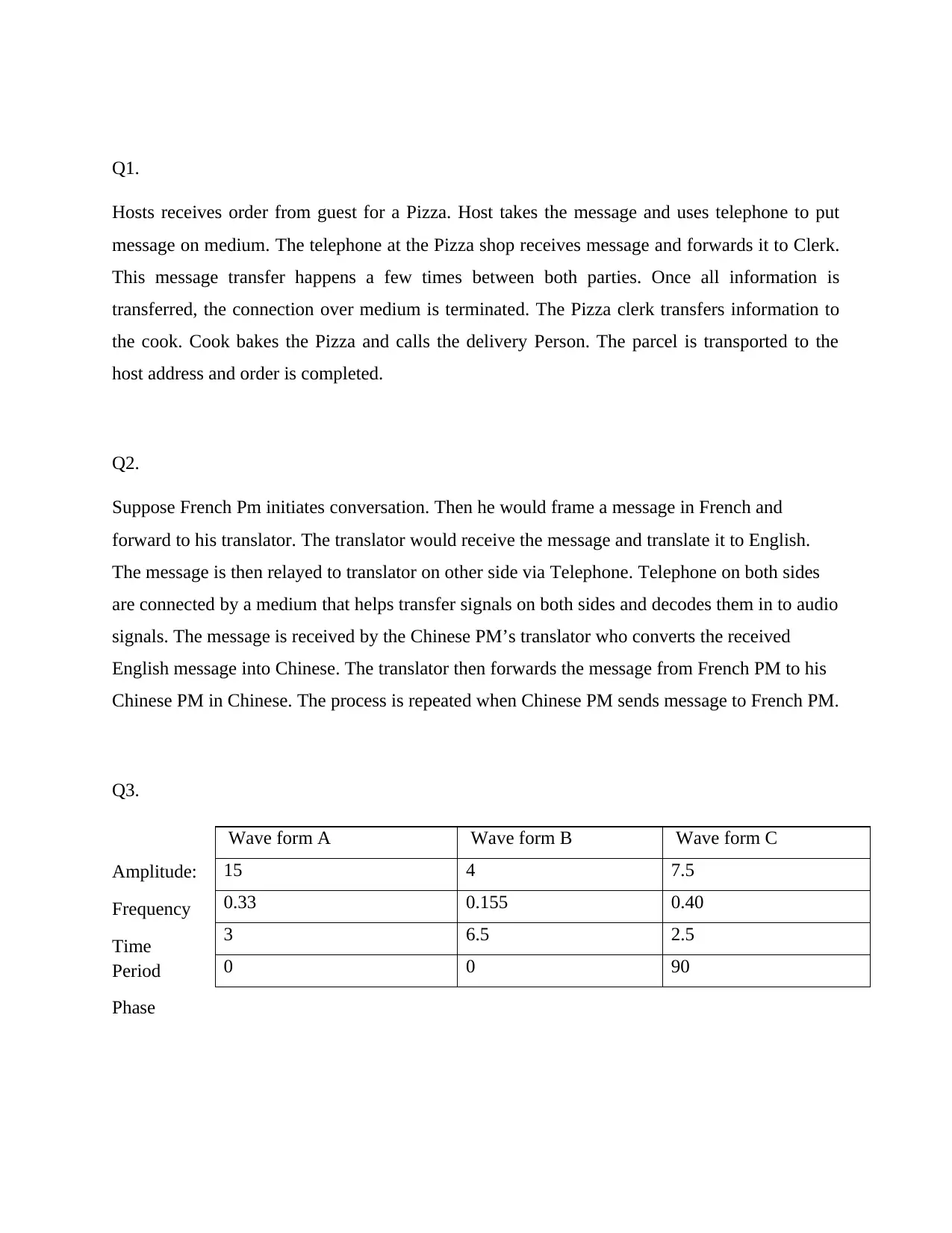
Q4. Equation for waveform A Sin (2 (f)t + θ)
10 Sin(2 (100) t)
Amplitude = 10. ; Frequency = 100 Hz ; Time Period = 1/100 =10msec Phase = 0◦
Document Page
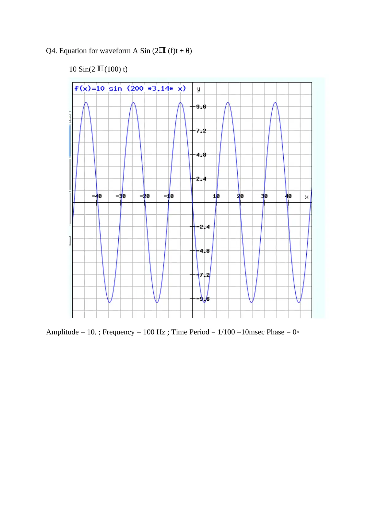
20 Sin(2 (30) t + 90)
Amplitude = 20. ; Frequency = 30 Hz ; Time Period = 1/30 = 33.33msec; Phase = 90◦
Document Page
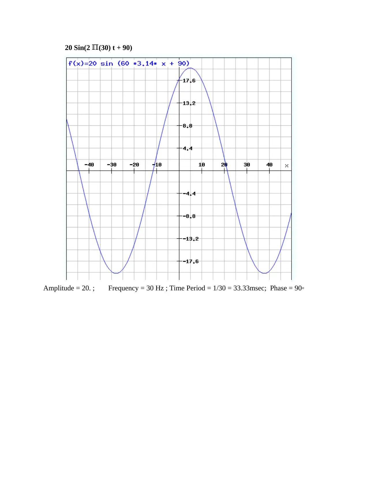
5 Sin(500 t + 180)
Amplitude = 5; Frequency = 250 Hz ; Time Period = 1/250 = 4msec; Phase = 180◦

Secure Best Marks with AI Grader

Need help grading? Try our AI Grader for instant feedback on your assignments.
Document Page
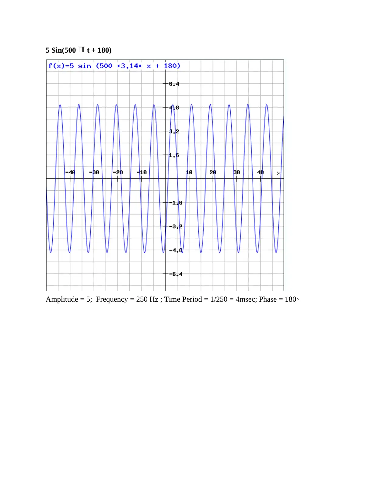
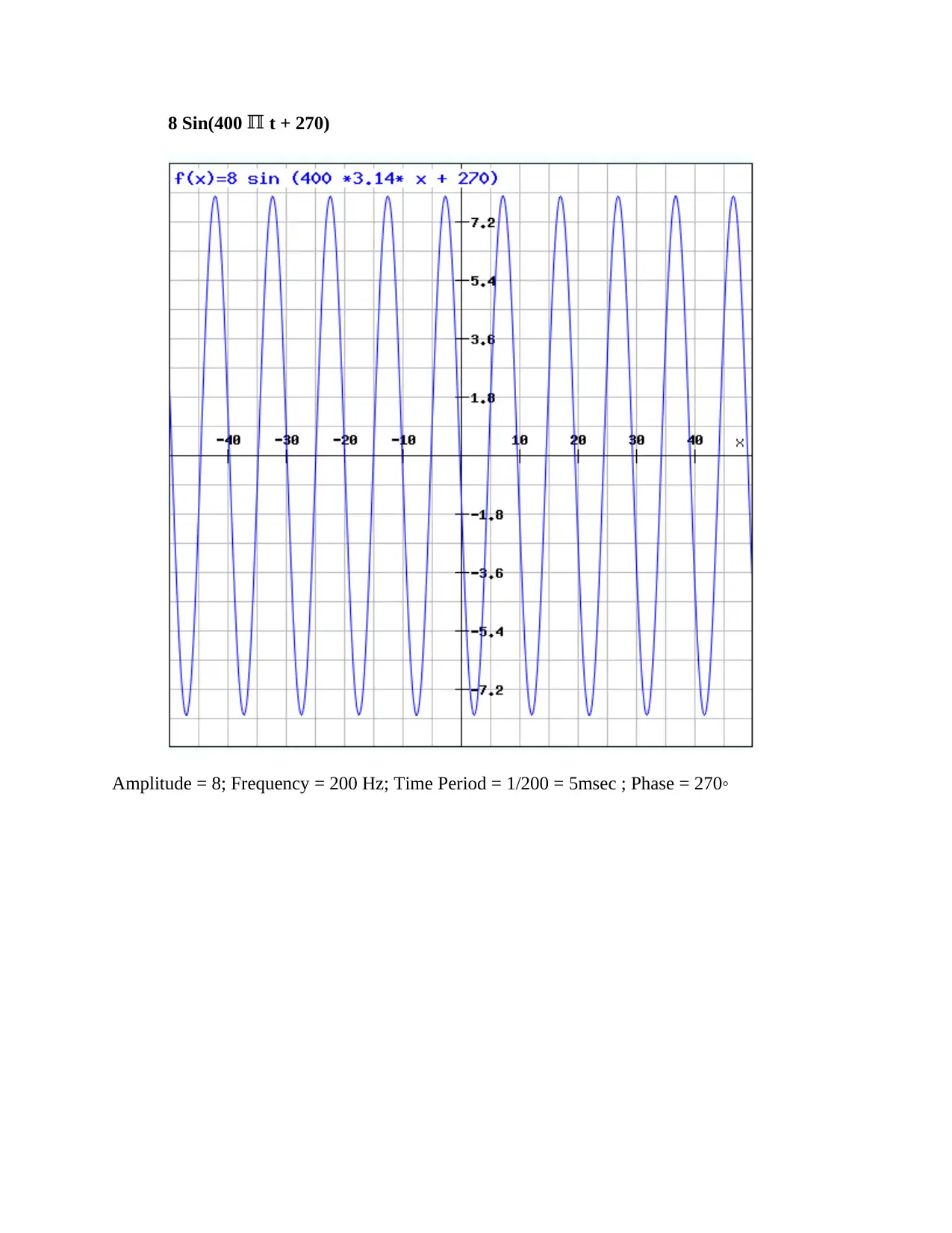
8 Sin(400 t + 270)
Amplitude = 8; Frequency = 200 Hz; Time Period = 1/200 = 5msec ; Phase = 270◦
Document Page
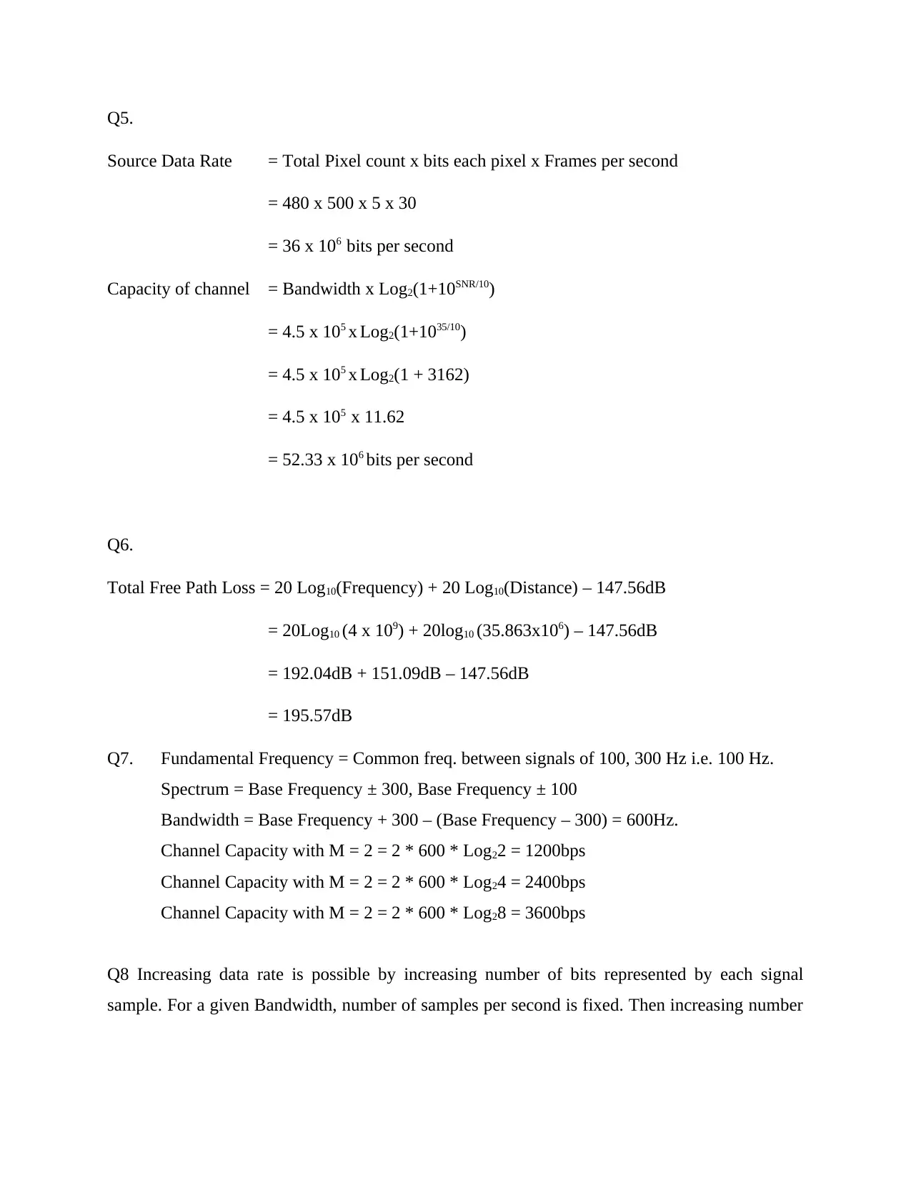
Q5.
Source Data Rate = Total Pixel count x bits each pixel x Frames per second
= 480 x 500 x 5 x 30
= 36 x 106 bits per second
Capacity of channel = Bandwidth x Log2(1+10SNR/10)
= 4.5 x 10⁵ x Log2(1+1035/10)
= 4.5 x 10⁵ x Log2(1 + 3162)
= 4.5 x 105 x 11.62
= 52.33 x 106 bits per second
Q6.
Total Free Path Loss = 20 Log10(Frequency) + 20 Log10(Distance) – 147.56dB
= 20Log10 (4 x 10⁹) + 20log10 (35.863x10⁶) – 147.56dB
= 192.04dB + 151.09dB – 147.56dB
= 195.57dB
Q7. Fundamental Frequency = Common freq. between signals of 100, 300 Hz i.e. 100 Hz.
Spectrum = Base Frequency ± 300, Base Frequency ± 100
Bandwidth = Base Frequency + 300 – (Base Frequency – 300) = 600Hz.
Channel Capacity with M = 2 = 2 * 600 * Log22 = 1200bps
Channel Capacity with M = 2 = 2 * 600 * Log24 = 2400bps
Channel Capacity with M = 2 = 2 * 600 * Log28 = 3600bps
Q8 Increasing data rate is possible by increasing number of bits represented by each signal
sample. For a given Bandwidth, number of samples per second is fixed. Then increasing number
Document Page
of bits per sample can increase data rate. As data rate is product of bandwidth and bits per
symbol.
Q9. To make communication possible between two devices, there needs to be a connection
between two nodes. The data can flow as continuous stream or in packets. Based on these
classifications, we can arrange connection as circuit switched network where data flow is like bit
stream and connection is directly between two points. Other scheme is packet switching where
data flows in form of packets. But problem with packet switching is variable path delays between
same two nodes. To solve this discrepancy, a specialized virtual circuit switching is added Packet
switching where all packets follow the same path to destination. This leads to uniform delay and
in order packet delivery. Thus Packet switching is beneficial as it allows dynamic Bandwidth
usage of channel among several users on demand basis which is not possible in circuit switching.
The bandwidth is fixed and leads to wastage when not in use.
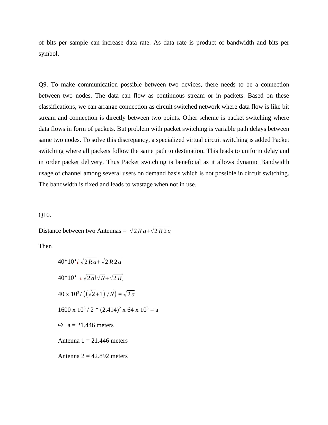
Q10.
Distance between two Antennas = 2 R a+ 2 R 2 a
Then
40*103 ¿ 2 R a+ 2 R 2 a
40*103 ¿ 2 a ( R+ 2 R )
40 x 103 / (( 2+1) R) = 2 a
1600 x 106 / 2 * (2.414)2 x 64 x 105 = a
a = 21.446 meters
Antenna 1 = 21.446 meters
Antenna 2 = 42.892 meters

Paraphrase This Document

Need a fresh take? Get an instant paraphrase of this document with our AI Paraphraser
Document Page
1 out of 8
circle_padding
hide_on_mobile
zoom_out_icon
[object Object]

Your All-in-One AI-Powered Toolkit for Academic Success.

Available 24*7 on WhatsApp / Email

[object Object]