Advanced Diploma in Engineering: Statics and Strength Assignment
VerifiedAdded on 2023/01/20
|11
|1958
|67
Homework Assignment
AI Summary
This document presents a comprehensive solution to a statics and strength of materials assignment, relevant to aeronautical engineering. The assignment covers a range of topics including landing gear repair, jackscrew mechanics, force resolution, helicopter force analysis, brake system analysis, bolted connections, friction, shear and tensile stress calculations, beam deflection, and shaft torsion. Each problem is addressed with detailed calculations, diagrams, and explanations, demonstrating the application of fundamental engineering principles. The solutions incorporate formulas for shear force, moment of inertia, shear stress, and deflection, along with considerations for static and dynamic friction, bolt design, and welding techniques. The assignment includes references to key texts and resources in the field, providing a robust resource for students studying statics and strength of materials in an aeronautical context.
Q1.
Landing gear repair.
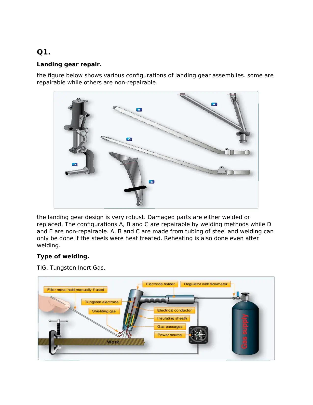
the figure below shows various configurations of landing gear assemblies. some are
repairable while others are non-repairable.
the landing gear design is very robust. Damaged parts are either welded or
replaced. The configurations A, B and C are repairable by welding methods while D
and E are non-repairable. A, B and C are made from tubing of steel and welding can
only be done if the steels were heat treated. Reheating is also done even after
welding.
Type of welding.
TIG. Tungsten Inert Gas.
Landing gear repair.
the figure below shows various configurations of landing gear assemblies. some are
repairable while others are non-repairable.
the landing gear design is very robust. Damaged parts are either welded or
replaced. The configurations A, B and C are repairable by welding methods while D
and E are non-repairable. A, B and C are made from tubing of steel and welding can
only be done if the steels were heat treated. Reheating is also done even after
welding.
Type of welding.
TIG. Tungsten Inert Gas.
Paraphrase This Document
Need a fresh take? Get an instant paraphrase of this document with our AI Paraphraser
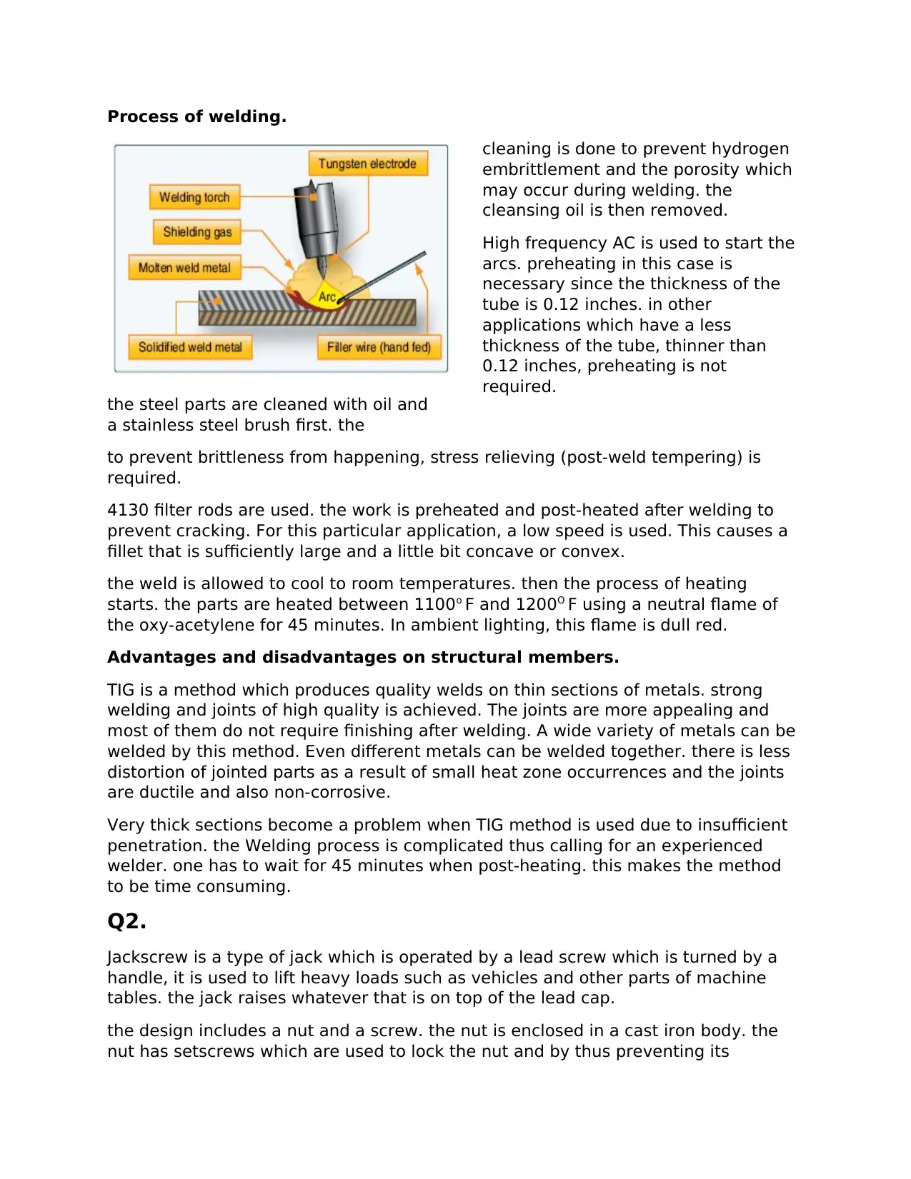
Process of welding.
the steel parts are cleaned with oil and
a stainless steel brush first. the
cleaning is done to prevent hydrogen
embrittlement and the porosity which
may occur during welding. the
cleansing oil is then removed.
High frequency AC is used to start the
arcs. preheating in this case is
necessary since the thickness of the
tube is 0.12 inches. in other
applications which have a less
thickness of the tube, thinner than
0.12 inches, preheating is not
required.
to prevent brittleness from happening, stress relieving (post-weld tempering) is
required.
4130 filter rods are used. the work is preheated and post-heated after welding to
prevent cracking. For this particular application, a low speed is used. This causes a
fillet that is sufficiently large and a little bit concave or convex.
the weld is allowed to cool to room temperatures. then the process of heating
starts. the parts are heated between 1100o F and 1200O F using a neutral flame of
the oxy-acetylene for 45 minutes. In ambient lighting, this flame is dull red.
Advantages and disadvantages on structural members.
TIG is a method which produces quality welds on thin sections of metals. strong
welding and joints of high quality is achieved. The joints are more appealing and
most of them do not require finishing after welding. A wide variety of metals can be
welded by this method. Even different metals can be welded together. there is less
distortion of jointed parts as a result of small heat zone occurrences and the joints
are ductile and also non-corrosive.
Very thick sections become a problem when TIG method is used due to insufficient
penetration. the Welding process is complicated thus calling for an experienced
welder. one has to wait for 45 minutes when post-heating. this makes the method
to be time consuming.
Q2.
Jackscrew is a type of jack which is operated by a lead screw which is turned by a
handle, it is used to lift heavy loads such as vehicles and other parts of machine
tables. the jack raises whatever that is on top of the lead cap.
the design includes a nut and a screw. the nut is enclosed in a cast iron body. the
nut has setscrews which are used to lock the nut and by thus preventing its
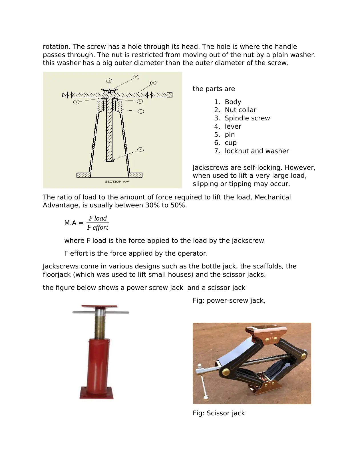
rotation. The screw has a hole through its head. The hole is where the handle
passes through. The nut is restricted from moving out of the nut by a plain washer.
this washer has a big outer diameter than the outer diameter of the screw.
the parts are
1. Body
2. Nut collar
3. Spindle screw
4. lever
5. pin
6. cup
7. locknut and washer
Jackscrews are self-locking. However,
when used to lift a very large load,
slipping or tipping may occur.
The ratio of load to the amount of force required to lift the load, Mechanical
Advantage, is usually between 30% to 50%.
M.A = F load
F effort
where F load is the force appied to the load by the jackscrew
F effort is the force applied by the operator.
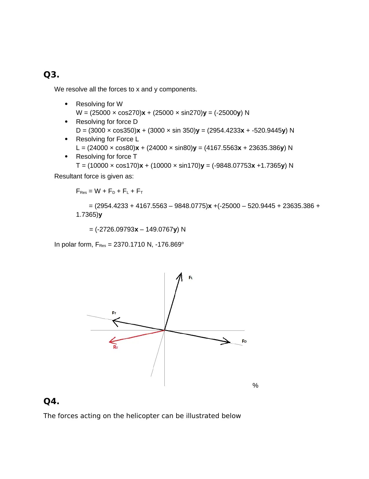
Jackscrews come in various designs such as the bottle jack, the scaffolds, the
floorjack (which was used to lift small houses) and the scissor jacks.
the figure below shows a power screw jack and a scissor jack
Fig: power-screw jack,
Fig: Scissor jack
passes through. The nut is restricted from moving out of the nut by a plain washer.
this washer has a big outer diameter than the outer diameter of the screw.
the parts are
1. Body
2. Nut collar
3. Spindle screw
4. lever
5. pin
6. cup
7. locknut and washer
Jackscrews are self-locking. However,
when used to lift a very large load,
slipping or tipping may occur.
The ratio of load to the amount of force required to lift the load, Mechanical
Advantage, is usually between 30% to 50%.
M.A = F load
F effort
where F load is the force appied to the load by the jackscrew
F effort is the force applied by the operator.
Jackscrews come in various designs such as the bottle jack, the scaffolds, the
floorjack (which was used to lift small houses) and the scissor jacks.
the figure below shows a power screw jack and a scissor jack
Fig: power-screw jack,
Fig: Scissor jack
⊘ This is a preview!⊘
Do you want full access?
Subscribe today to unlock all pages.
Trusted by 1+ million students worldwide
Q3.
We resolve all the forces to x and y components.
Resolving for W
W = (25000 × cos270)x + (25000 × sin270)y = (-25000y) N
Resolving for force D
D = (3000 × cos350)x + (3000 × sin 350)y = (2954.4233x + -520.9445y) N
Resolving for Force L
L = (24000 × cos80)x + (24000 × sin80)y = (4167.5563x + 23635.386y) N
Resolving for force T
T = (10000 × cos170)x + (10000 × sin170)y = (-9848.07753x +1.7365y) N
Resultant force is given as:
FRes = W + FD + FL + FT
= (2954.4233 + 4167.5563 – 9848.0775)x +(-25000 – 520.9445 + 23635.386 +
1.7365)y
= (-2726.09793x – 149.0767y) N
In polar form, FRes = 2370.1710 N, -176.869o
%
Q4.
The forces acting on the helicopter can be illustrated below
Paraphrase This Document
Need a fresh take? Get an instant paraphrase of this document with our AI Paraphraser
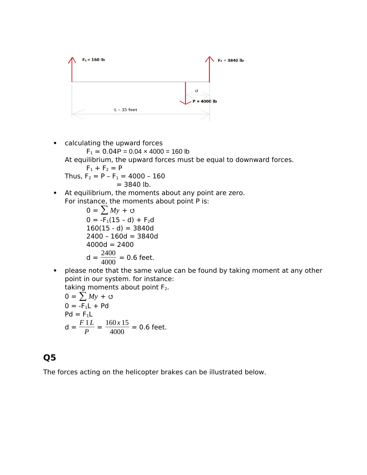
calculating the upward forces
F1 = 0.04P = 0.04 × 4000 = 160 lb
At equilibrium, the upward forces must be equal to downward forces.
F1 + F2 = P
Thus, F2 = P – F1 = 4000 – 160
= 3840 lb.
At equilibrium, the moments about any point are zero.
For instance, the moments about point P is:
0 = ∑ My + ↺
0 = -F1(15 – d) + F2d
160(15 - d) = 3840d
2400 – 160d = 3840d
4000d = 2400
d = 2400
4000 = 0.6 feet.
please note that the same value can be found by taking moment at any other
point in our system. for instance:
taking moments about point F2.
0 = ∑ My + ↺
0 = -F1L + Pd
Pd = F1L
d = F 1 L
P = 160 x 15
4000 = 0.6 feet.
Q5
The forces acting on the helicopter brakes can be illustrated below.
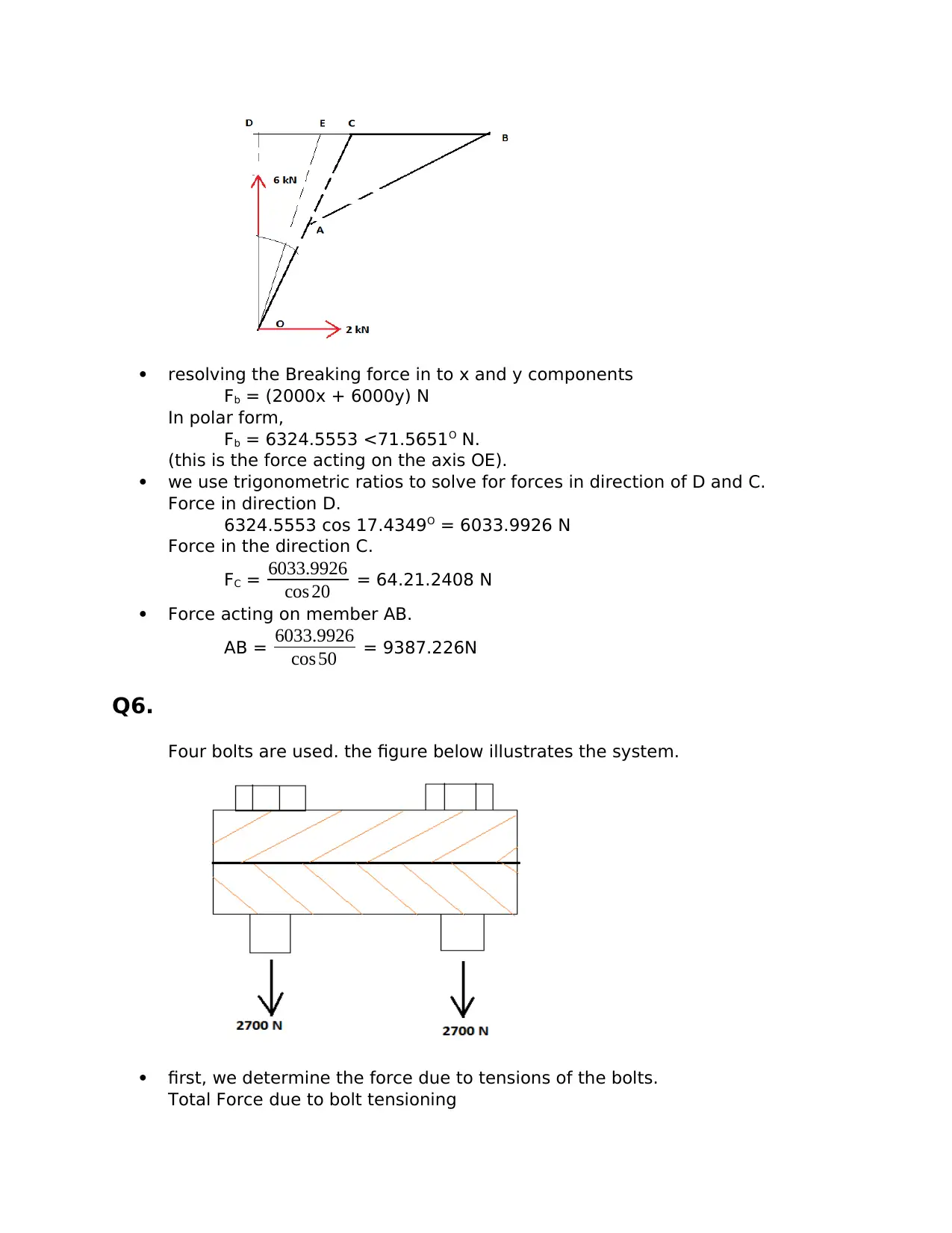
resolving the Breaking force in to x and y components
Fb = (2000x + 6000y) N
In polar form,
Fb = 6324.5553 <71.5651O N.
(this is the force acting on the axis OE).
we use trigonometric ratios to solve for forces in direction of D and C.
Force in direction D.
6324.5553 cos 17.4349O = 6033.9926 N
Force in the direction C.
FC = 6033.9926
cos 20 = 64.21.2408 N
Force acting on member AB.
AB = 6033.9926
cos 50 = 9387.226N
Q6.
Four bolts are used. the figure below illustrates the system.
first, we determine the force due to tensions of the bolts.
Total Force due to bolt tensioning
⊘ This is a preview!⊘
Do you want full access?
Subscribe today to unlock all pages.
Trusted by 1+ million students worldwide
FN = 2700 × 4 = 10800 N (since there are 4 bolts each causing 2700 N tension)
force due to friction is a product of coefficient of friction between the plates
and the normal force acting on the plates. i.e.
Fst. =
⩁sFN = 0.4 × 10800 = 4320 N.
Q7.
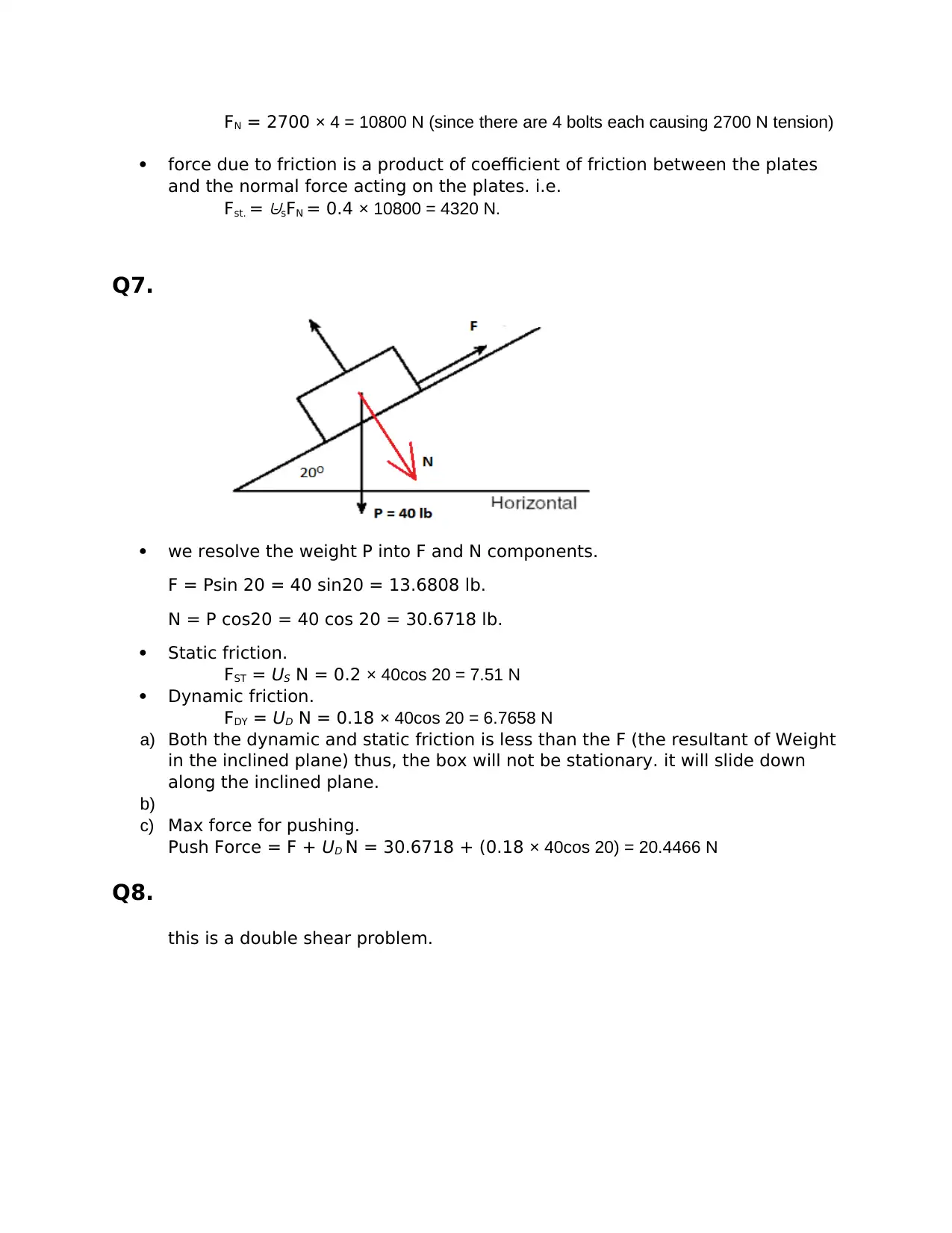
we resolve the weight P into F and N components.
F = Psin 20 = 40 sin20 = 13.6808 lb.
N = P cos20 = 40 cos 20 = 30.6718 lb.
Static friction.
FST = US N = 0.2 × 40cos 20 = 7.51 N
Dynamic friction.
FDY = UD N = 0.18 × 40cos 20 = 6.7658 N
a) Both the dynamic and static friction is less than the F (the resultant of Weight
in the inclined plane) thus, the box will not be stationary. it will slide down
along the inclined plane.
b)
c) Max force for pushing.
Push Force = F + UD N = 30.6718 + (0.18 × 40cos 20) = 20.4466 N
Q8.
this is a double shear problem.
force due to friction is a product of coefficient of friction between the plates
and the normal force acting on the plates. i.e.
Fst. =
⩁sFN = 0.4 × 10800 = 4320 N.
Q7.
we resolve the weight P into F and N components.
F = Psin 20 = 40 sin20 = 13.6808 lb.
N = P cos20 = 40 cos 20 = 30.6718 lb.
Static friction.
FST = US N = 0.2 × 40cos 20 = 7.51 N
Dynamic friction.
FDY = UD N = 0.18 × 40cos 20 = 6.7658 N
a) Both the dynamic and static friction is less than the F (the resultant of Weight
in the inclined plane) thus, the box will not be stationary. it will slide down
along the inclined plane.
b)
c) Max force for pushing.
Push Force = F + UD N = 30.6718 + (0.18 × 40cos 20) = 20.4466 N
Q8.
this is a double shear problem.
Paraphrase This Document
Need a fresh take? Get an instant paraphrase of this document with our AI Paraphraser
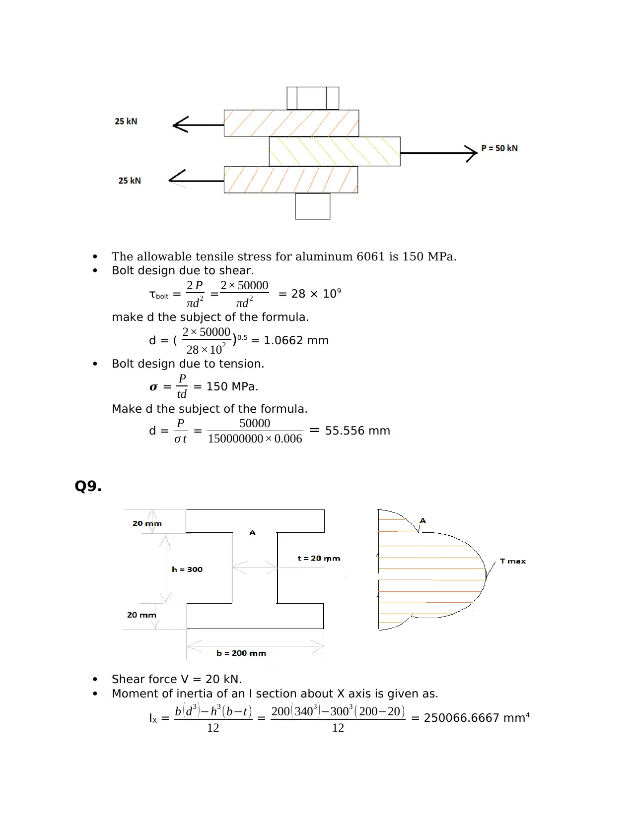
The allowable tensile stress for aluminum 6061 is 150 MPa.
Bolt design due to shear.
τbolt = 2 P
πd2 = 2× 50000
πd2 = 28 × 109
make d the subject of the formula.
d = ( 2× 50000
28 ×102 )0.5 = 1.0662 mm
Bolt design due to tension.
𝝈 = P
td = 150 MPa.
Make d the subject of the formula.
d = P
σ t = 50000
150000000× 0.006 = 55.556 mm
Q9.
Shear force V = 20 kN.
Moment of inertia of an I section about X axis is given as.
IX = b ( d3 )−h3 (b−t)
12 = 200 ( 3403 ) −3003 ( 200−20)
12 = 250066.6667 mm4
= (2.500667 × 10⁻⁴) m4
Shear stress on the web.
Ƭ =
V
8¿ [ b ( h2−h1
2 ) +t ( h1
2−t h1 ) ] ¿
Maximum shear stress.
y1= 0.
Substituting this into the formula above.
Ƭmax =
V
8¿ [b ( h2−h1
2 )+t ( h1
2 ) ] ¿
= 20000
8 ×2.500667 ×−4 ×0.02 [ 0.2 ( 0.342−0.32 ) + 0.02 ( 0.32 ) ] = 3.4591 MPa.
At point A, at the junction of the web and the flange,
y1= h1
2
Substituting this in the shear stress formula we get.
ƬA =
V
8¿ [ b ( h2−h1
2 ) ] ¿ = 20000
8 ×2.500667 ×−4 ×0.02 [ 0.2 ( 0.342−0.32 ) ]
= 255931.7481 Pa
= 0.2559 MPa.
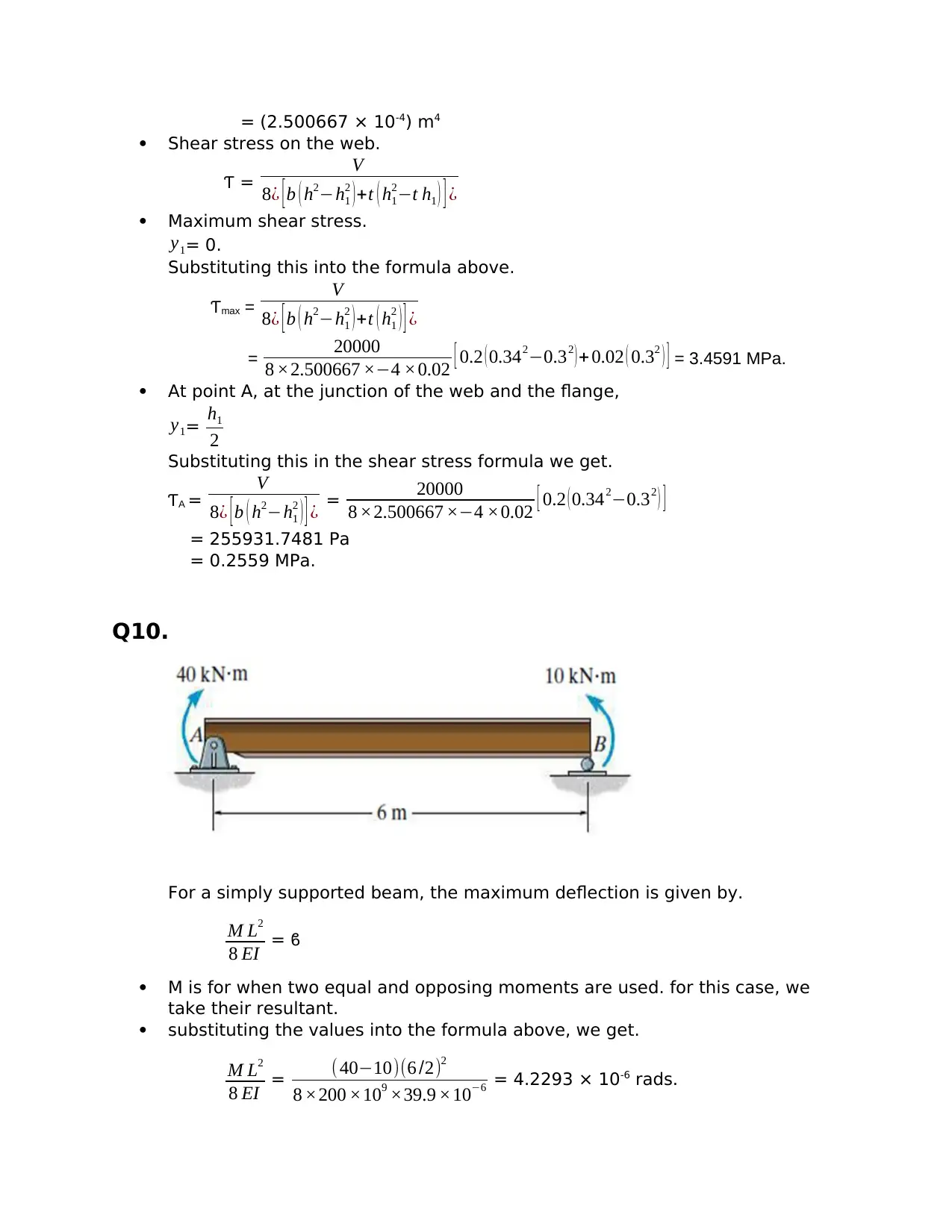
Q10.
For a simply supported beam, the maximum deflection is given by.
M L2
8 EI = ϐ
M is for when two equal and opposing moments are used. for this case, we
take their resultant.
substituting the values into the formula above, we get.
M L2
8 EI = (40−10)(6 /2)2
8 ×200 ×109 ×39.9 ×10−6 = 4.2293 × 10⁻⁶ rads.
Shear stress on the web.
Ƭ =
V
8¿ [ b ( h2−h1
2 ) +t ( h1
2−t h1 ) ] ¿
Maximum shear stress.
y1= 0.
Substituting this into the formula above.
Ƭmax =
V
8¿ [b ( h2−h1
2 )+t ( h1
2 ) ] ¿
= 20000
8 ×2.500667 ×−4 ×0.02 [ 0.2 ( 0.342−0.32 ) + 0.02 ( 0.32 ) ] = 3.4591 MPa.
At point A, at the junction of the web and the flange,
y1= h1
2
Substituting this in the shear stress formula we get.
ƬA =
V
8¿ [ b ( h2−h1
2 ) ] ¿ = 20000
8 ×2.500667 ×−4 ×0.02 [ 0.2 ( 0.342−0.32 ) ]
= 255931.7481 Pa
= 0.2559 MPa.
Q10.
For a simply supported beam, the maximum deflection is given by.
M L2
8 EI = ϐ
M is for when two equal and opposing moments are used. for this case, we
take their resultant.
substituting the values into the formula above, we get.
M L2
8 EI = (40−10)(6 /2)2
8 ×200 ×109 ×39.9 ×10−6 = 4.2293 × 10⁻⁶ rads.
⊘ This is a preview!⊘
Do you want full access?
Subscribe today to unlock all pages.
Trusted by 1+ million students worldwide
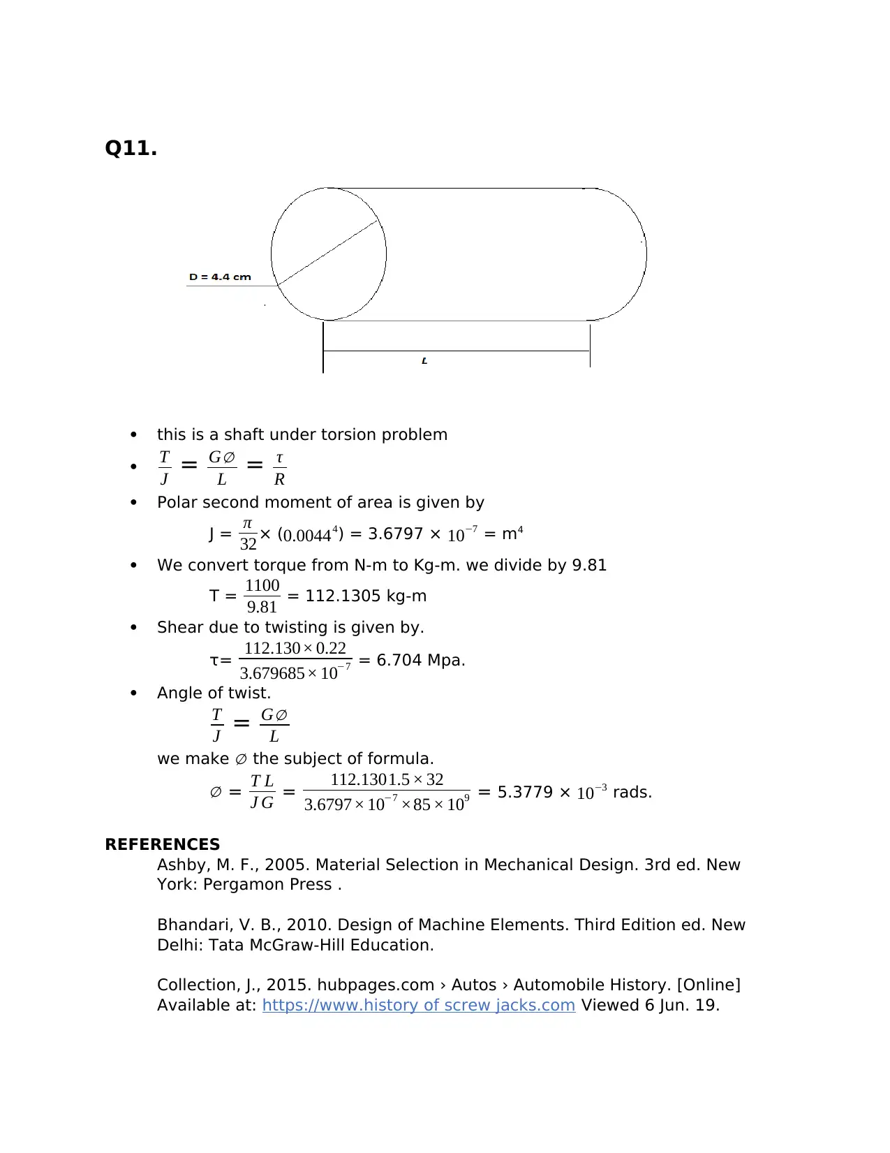
Q11.
this is a shaft under torsion problem
T
J = G∅
L = τ
R
Polar second moment of area is given by
J = π
32× (0.00444) = 3.6797 × 10−7 = m4
We convert torque from N-m to Kg-m. we divide by 9.81
T = 1100
9.81 = 112.1305 kg-m
Shear due to twisting is given by.
τ= 112.130× 0.22
3.679685× 10−7 = 6.704 Mpa.
Angle of twist.
T
J = G∅
L
we make ∅ the subject of formula.
∅ = T L
J G = 112.1301.5 × 32
3.6797× 10−7 ×85 × 109 = 5.3779 × 10⁻³ rads.
REFERENCES
Ashby, M. F., 2005. Material Selection in Mechanical Design. 3rd ed. New
York: Pergamon Press .
Bhandari, V. B., 2010. Design of Machine Elements. Third Edition ed. New
Delhi: Tata McGraw-Hill Education.
Collection, J., 2015. hubpages.com › Autos › Automobile History. [Online]
Available at: https://www.history of screw jacks.com Viewed 6 Jun. 19.
Paraphrase This Document
Need a fresh take? Get an instant paraphrase of this document with our AI Paraphraser
Fasteners, C. o., 2005. Technical Reference Guide. Ninth Edition ed. Winona,
Minnesota: Fastenal Industrial & Construction Supplies.
Gupta, R. K. &. J., 2005. Theory of Machines. Revised Edition ed. Punjab,
India: S. Chand and Company.
J.J. Fereira, M. B. M. G., 2004. Review of the risks associated with pushing and
pulling heavy loads.. first ed. Shefield: Health and sfety Laboratory.
Kempster, M. H. A., 1984. Engineering Design III. London: Hodder and
Stoughton Ltd.
Marshek, R. C. J. &. K. M., 2012. Fundamental of Machine Design
Components. Fifth Edition ed. s.l.:Jonh Wiley & Sons Inc..
Naik, V. K., Apr 15, 2015. Slideshare. [Online] Available at:
http://www.slideshare.net/abhisheknaik018/screw-jack-47011977 Viewed 6
Jun. 19.
Nisbet, R. G. B. &. J. K., 2015. Shigley's Mechanical Engineering desin. Tenth
ed. New York: McGraw-Hill.
Nyangasi, 18 December, 2006.
http://webcache.googleusercontent.com/search. [Online] Available at:
http://mechanical.uonbi.ac.ke/sites/default/files/cae/engineering/mechanical/
POWER%20SCREWS.doc. Viewed 6 Jun. 19.
1 out of 11
Your All-in-One AI-Powered Toolkit for Academic Success.
+13062052269
info@desklib.com
Available 24*7 on WhatsApp / Email
![[object Object]](/_next/static/media/star-bottom.7253800d.svg)
Unlock your academic potential
Copyright © 2020–2026 A2Z Services. All Rights Reserved. Developed and managed by ZUCOL.