Advanced Dynamic Modeling, Simulation and Control of Quad Bike's Engine and Drive Train Performance
VerifiedAdded on 2023/06/07
|15
|1301
|293
AI Summary
This report covers the application of mechanical control in quad bike's engine and drive train performance. It includes mathematical model schematic, free body diagram, Simulink model, PID controller, and system stability analysis.
Contribute Materials
Your contribution can guide someone’s learning journey. Share your
documents today.
1
CQU MELBOURNE CAMPUS
MASTER OF MECHANICAL ENGINEERING
ADVANCED DYNAMIC MODELING SIMULATION AND CONTROL OF DYNAMIC
SYSTEM
PROJECT 2
STUDENT NAME
STUDENT ID NUMBER
PROFESSOR (TUTOR)
DATE OF SUBMISSION
CQU MELBOURNE CAMPUS
MASTER OF MECHANICAL ENGINEERING
ADVANCED DYNAMIC MODELING SIMULATION AND CONTROL OF DYNAMIC
SYSTEM
PROJECT 2
STUDENT NAME
STUDENT ID NUMBER
PROFESSOR (TUTOR)
DATE OF SUBMISSION
Secure Best Marks with AI Grader
Need help grading? Try our AI Grader for instant feedback on your assignments.

2
TEAM REPORT COVER SHEET
TEAM REPORT COVER SHEET
3
APPLICATION OF MECHANICAL CONTROL
PART A
Quad bike’s engine and drive train performance
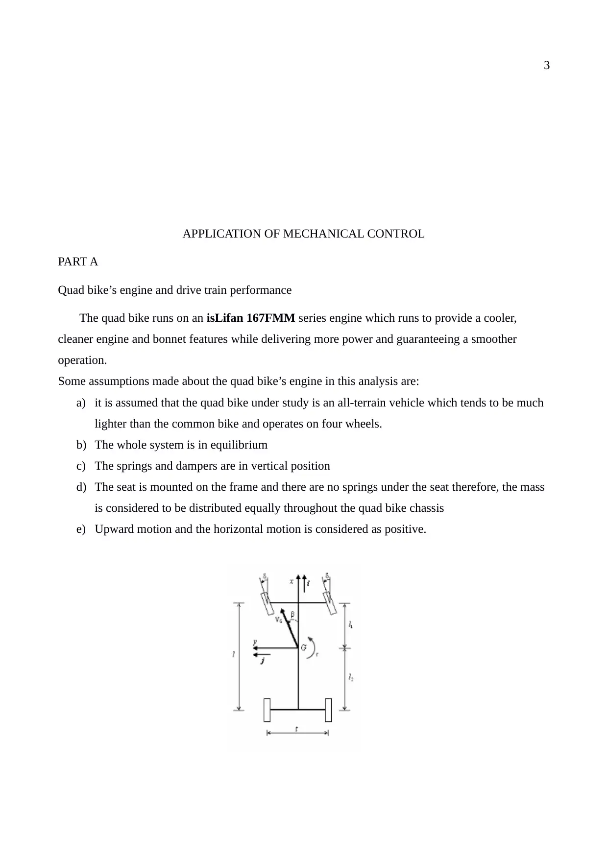
The quad bike runs on an isLifan 167FMM series engine which runs to provide a cooler,
cleaner engine and bonnet features while delivering more power and guaranteeing a smoother
operation.
Some assumptions made about the quad bike’s engine in this analysis are:
a) it is assumed that the quad bike under study is an all-terrain vehicle which tends to be much
lighter than the common bike and operates on four wheels.
b) The whole system is in equilibrium
c) The springs and dampers are in vertical position
d) The seat is mounted on the frame and there are no springs under the seat therefore, the mass
is considered to be distributed equally throughout the quad bike chassis
e) Upward motion and the horizontal motion is considered as positive.
4
Payload specifications (details and variations)- adapted from Yamaha Grizzly 700se model
Parameter Value
Engine type Liquid cooled, 4-stroke engine
Displacement 708.0 cc
Horse Power 38.5 Hp @ 6000 rpm
Torque 36 Nm @ 5000 rpm
Clutch type Centrifugal force
Final transmission V-belt drive
Gear Ratio 3.6.7
Compression ratio 10.0.1
Ignition TCI
Starter system Electric start
PART B
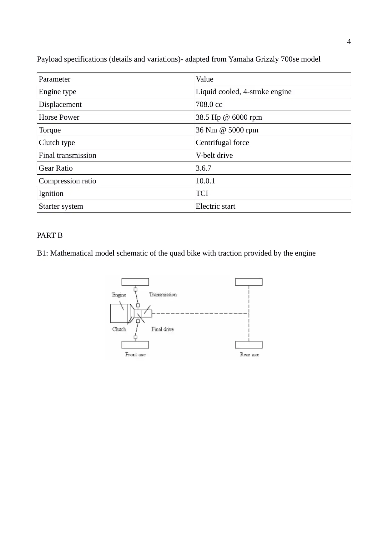
B1: Mathematical model schematic of the quad bike with traction provided by the engine
Secure Best Marks with AI Grader
Need help grading? Try our AI Grader for instant feedback on your assignments.
5
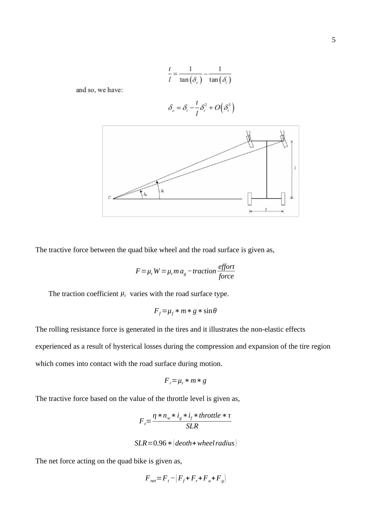
The tractive force between the quad bike wheel and the road surface is given as,
F=μt W =μt m ag −traction effort
force
The traction coefficient μt varies with the road surface type.
Ff =μf ∗ m∗ g ∗ sinθ
The rolling resistance force is generated in the tires and it illustrates the non-elastic effects
experienced as a result of hysterical losses during the compression and expansion of the tire region
which comes into contact with the road surface during motion.
Fr=μr ∗ m∗ g
The tractive force based on the value of the throttle level is given as,
Ft= η ∗nw ∗ ig ∗if ∗throttle ∗ τ
SLR
SLR=0.96 ∗ ( deoth+ wheel radius )
The net force acting on the quad bike is given as,
Fnet=Ft − ( Ff + Fr + Fa + Fg )
6
my = -k(y-yG)-c(y'-yG') implie
y +2ζω_ny'+ωn^2y
2 ζ ωny
' G+ ωn yG
It is progressed further as,
y p= ωn
2 Y G
ωn
2 − ωG
2 sin ( ωG t ) = Y G
1 −r2 sin ( ωG t )
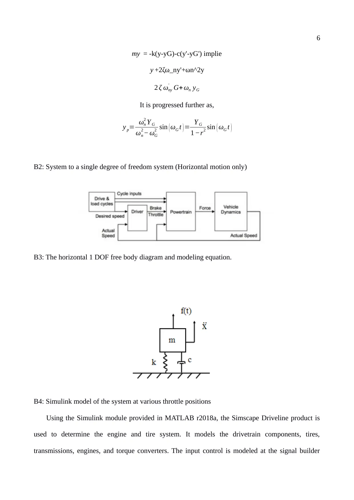
B2: System to a single degree of freedom system (Horizontal motion only)
B3: The horizontal 1 DOF free body diagram and modeling equation.
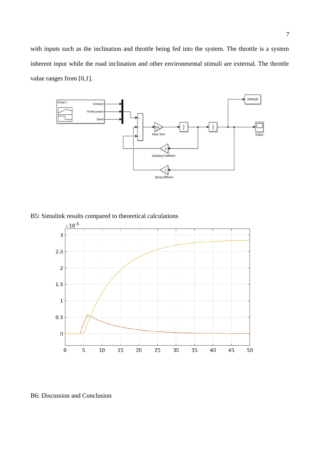
B4: Simulink model of the system at various throttle positions
Using the Simulink module provided in MATLAB r2018a, the Simscape Driveline product is
used to determine the engine and tire system. It models the drivetrain components, tires,
transmissions, engines, and torque converters. The input control is modeled at the signal builder
7
with inputs such as the inclination and throttle being fed into the system. The throttle is a system
inherent input while the road inclination and other environmental stimuli are external. The throttle
value ranges from [0,1].
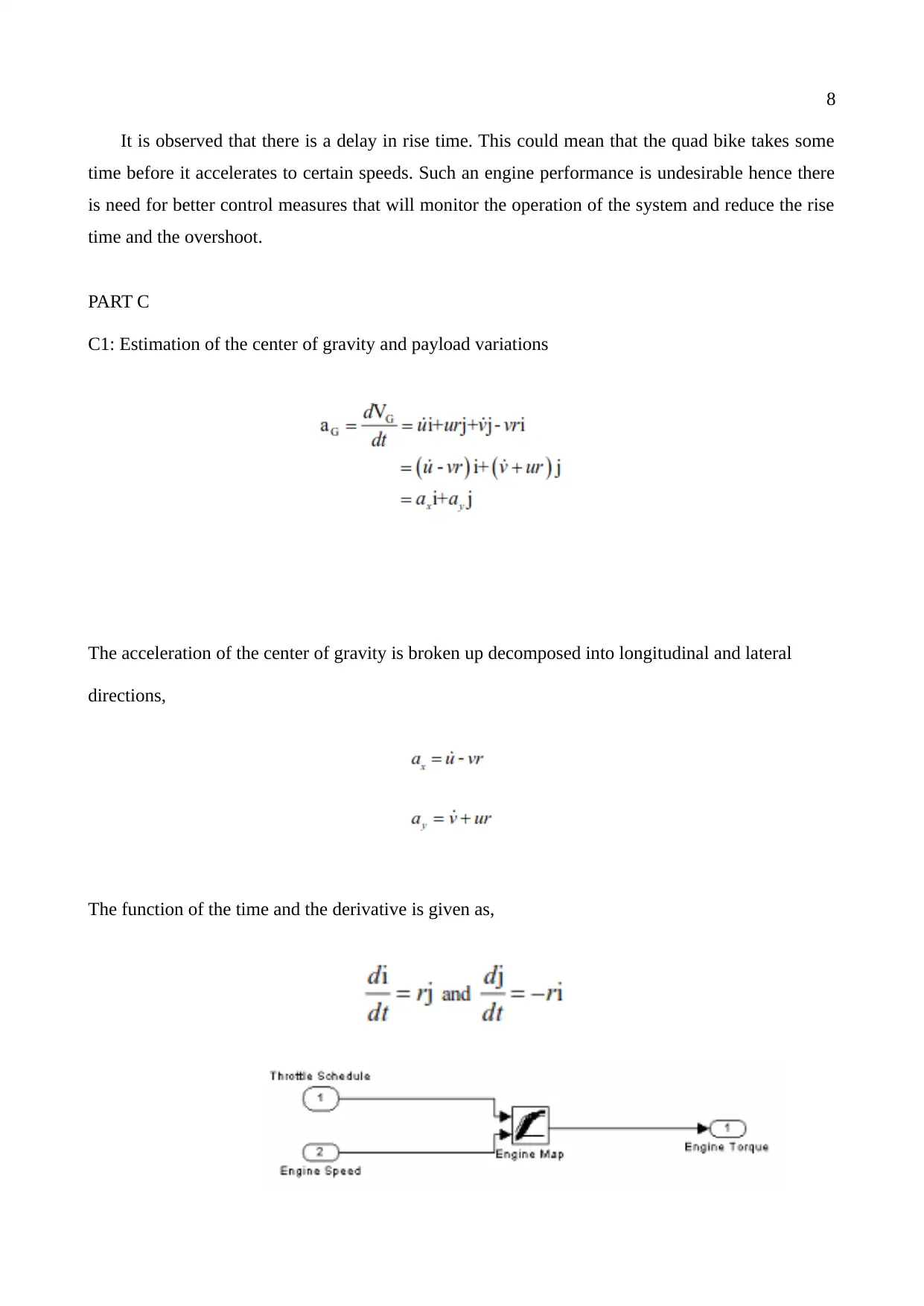
B5: Simulink results compared to theoretical calculations
B6: Discussion and Conclusion
Paraphrase This Document
Need a fresh take? Get an instant paraphrase of this document with our AI Paraphraser
8
It is observed that there is a delay in rise time. This could mean that the quad bike takes some
time before it accelerates to certain speeds. Such an engine performance is undesirable hence there
is need for better control measures that will monitor the operation of the system and reduce the rise
time and the overshoot.
PART C
C1: Estimation of the center of gravity and payload variations
The acceleration of the center of gravity is broken up decomposed into longitudinal and lateral
directions,
The function of the time and the derivative is given as,
9
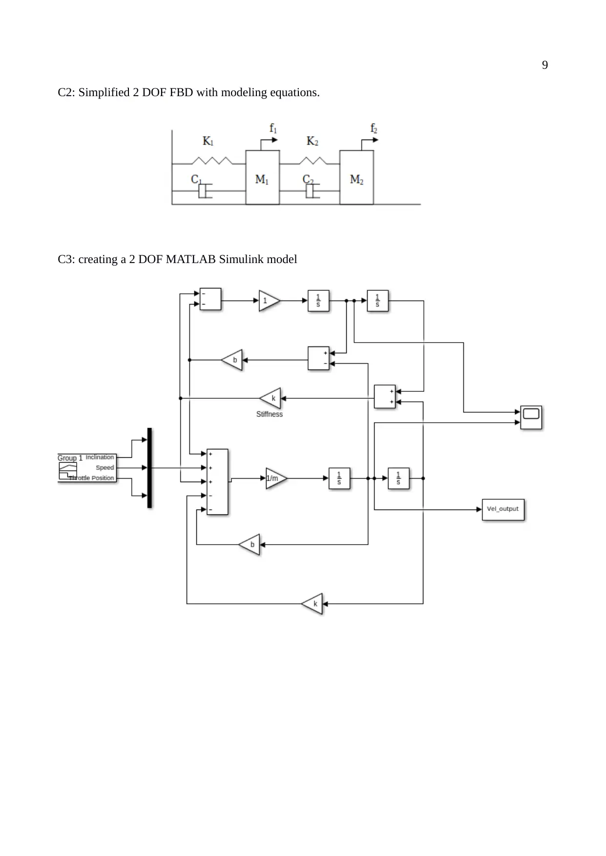
C2: Simplified 2 DOF FBD with modeling equations.
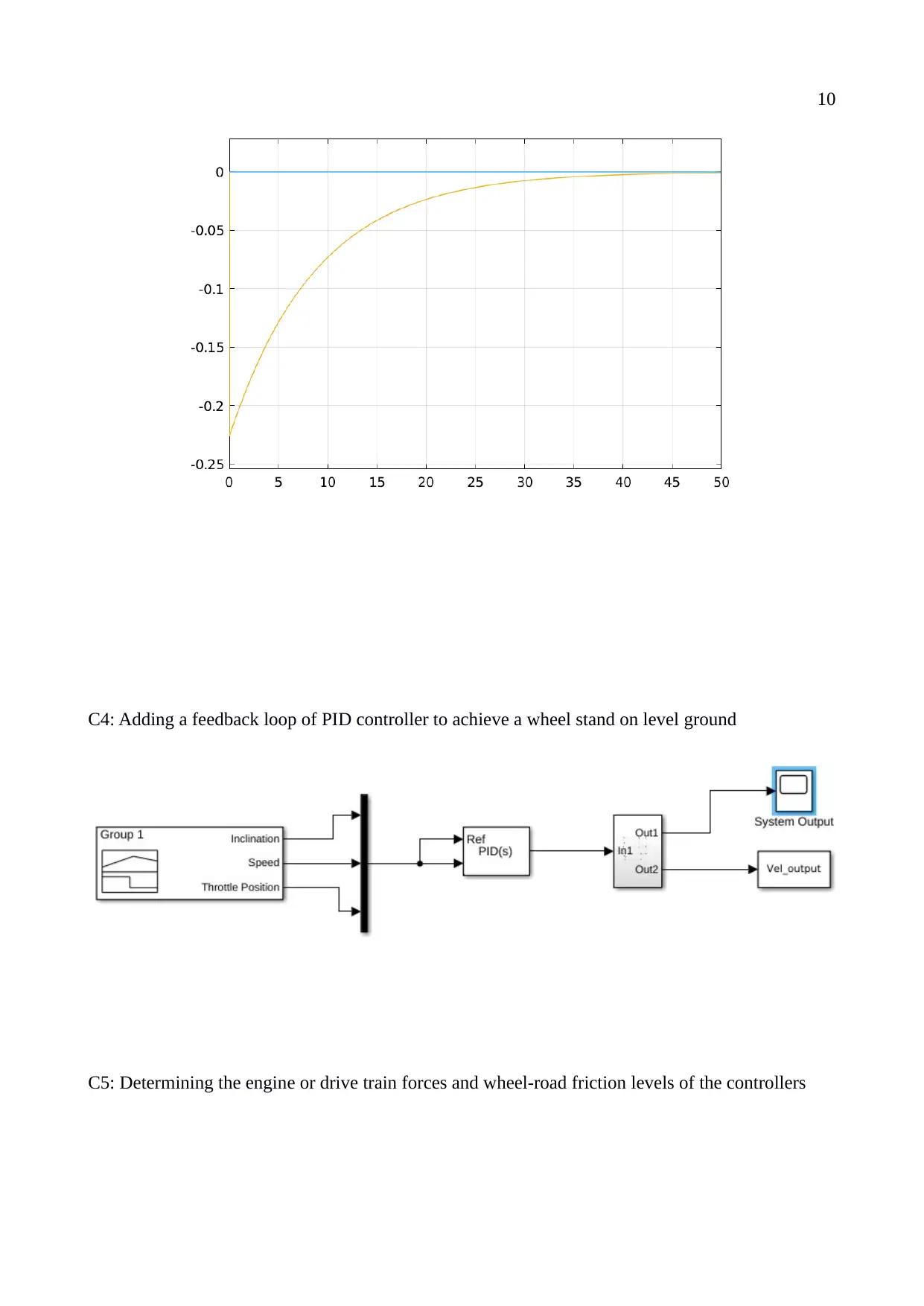
C3: creating a 2 DOF MATLAB Simulink model
C2: Simplified 2 DOF FBD with modeling equations.
C3: creating a 2 DOF MATLAB Simulink model
10
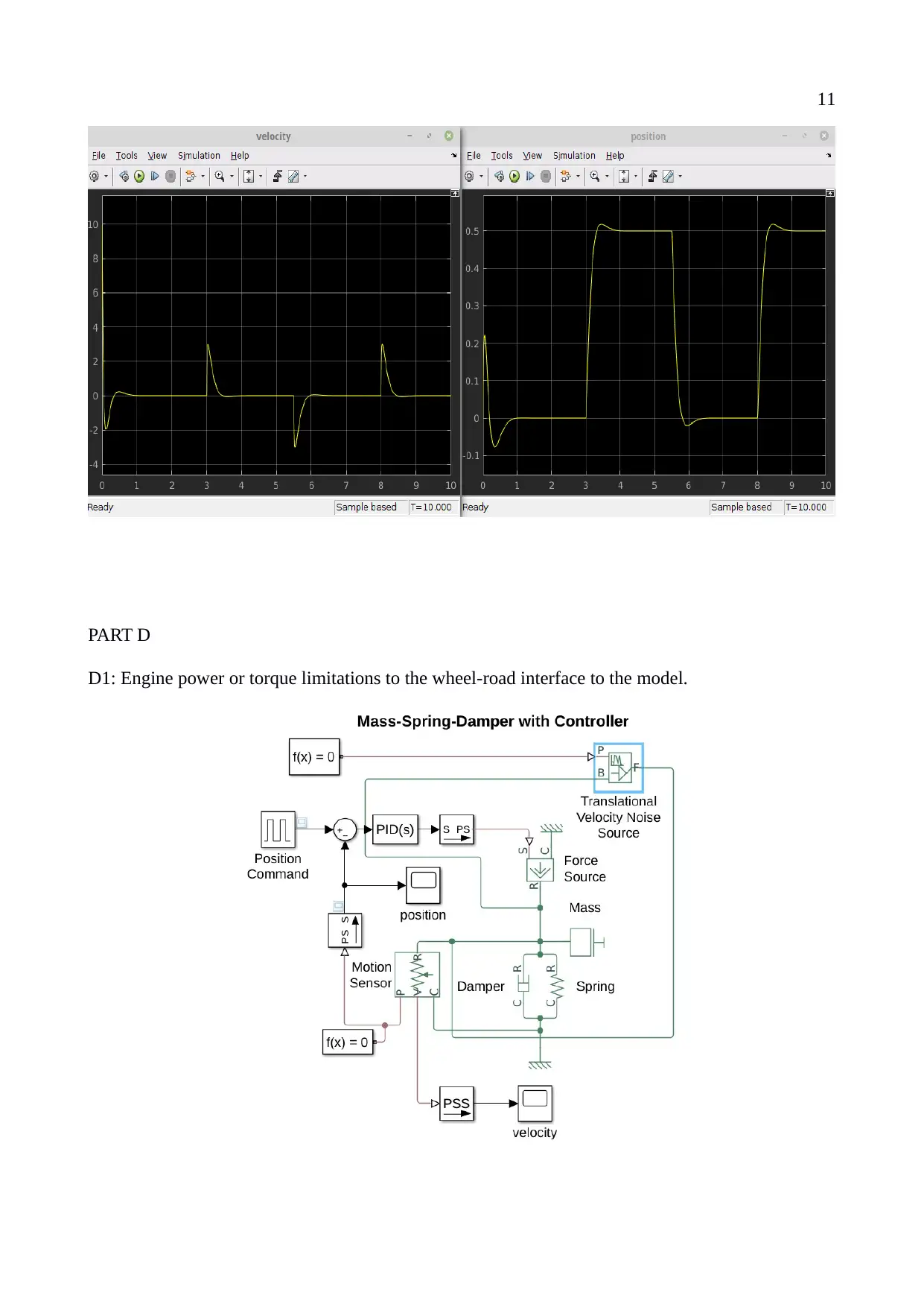
C4: Adding a feedback loop of PID controller to achieve a wheel stand on level ground
C5: Determining the engine or drive train forces and wheel-road friction levels of the controllers
C4: Adding a feedback loop of PID controller to achieve a wheel stand on level ground
C5: Determining the engine or drive train forces and wheel-road friction levels of the controllers
Secure Best Marks with AI Grader
Need help grading? Try our AI Grader for instant feedback on your assignments.
11
PART D
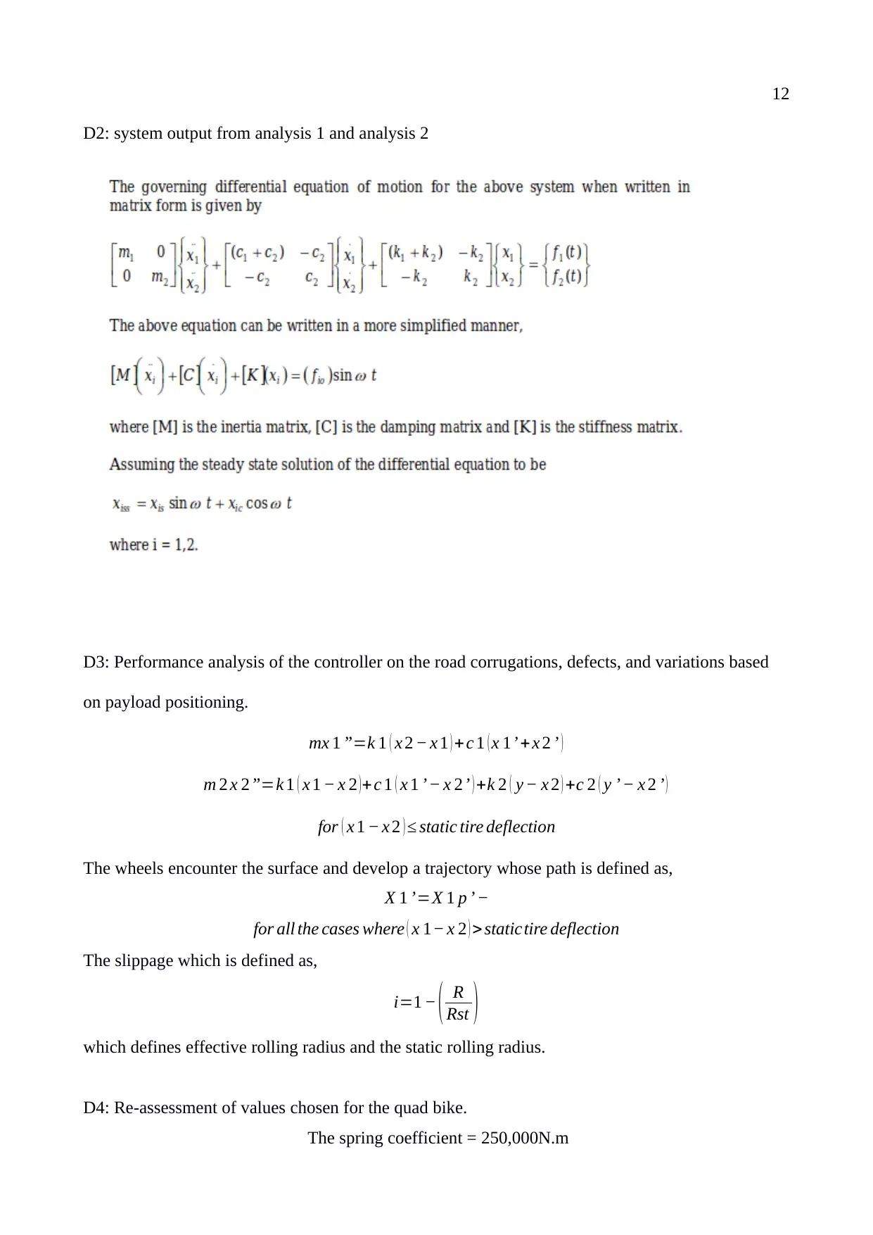
D1: Engine power or torque limitations to the wheel-road interface to the model.
PART D
D1: Engine power or torque limitations to the wheel-road interface to the model.
12
D2: system output from analysis 1 and analysis 2
D3: Performance analysis of the controller on the road corrugations, defects, and variations based
on payload positioning.
mx 1 ”=k 1 ( x 2 − x 1 ) +c 1 ( x 1’ +x 2 ’ )
m 2 x 2”=k 1 ( x 1 − x 2 )+c 1 ( x 1 ’− x 2’ ) +k 2 ( y − x 2 ) +c 2 ( y ’ − x 2 ’ )
for ( x 1 − x 2 ) ≤ static tire deflection
The wheels encounter the surface and develop a trajectory whose path is defined as,
X 1 ’=X 1 p ’ −
for all the cases where ( x 1− x 2 ) >statictire deflection
The slippage which is defined as,
i=1 − ( R
Rst )
which defines effective rolling radius and the static rolling radius.
D4: Re-assessment of values chosen for the quad bike.
The spring coefficient = 250,000N.m
13
The damping coefficient = 25,500 Ns/m
The simulation output results in a difference of approximately 8.5 times the value with the added
controller on the system,
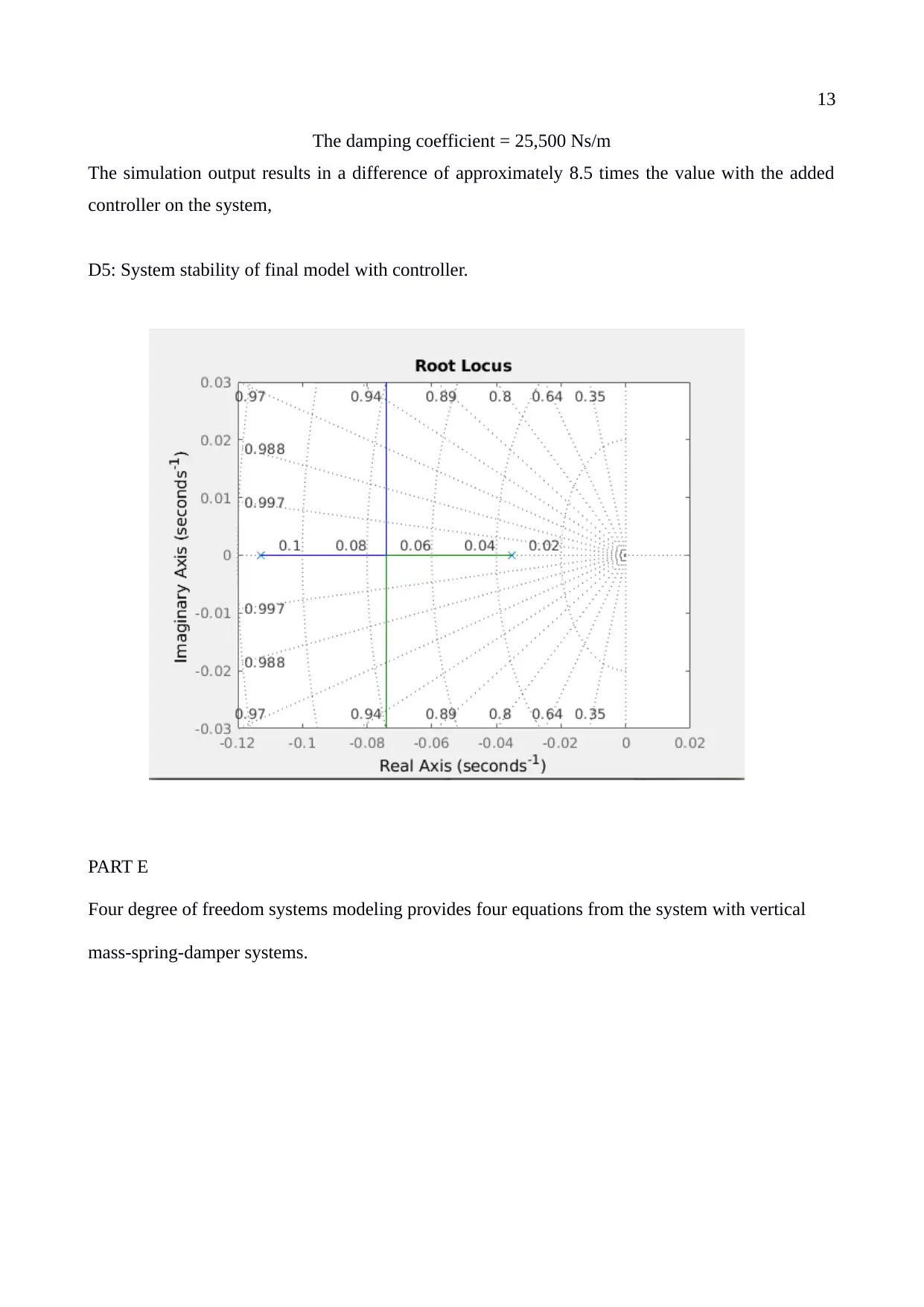
D5: System stability of final model with controller.
PART E
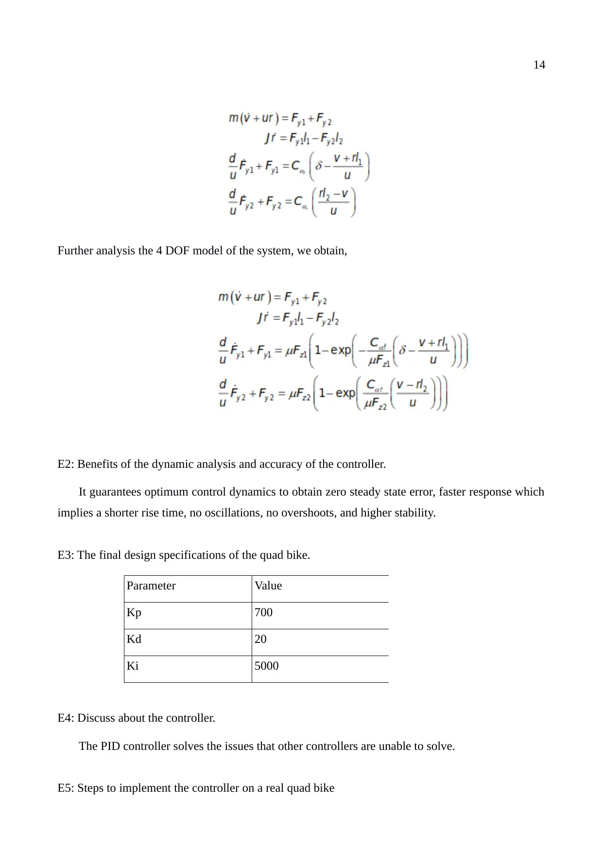
Four degree of freedom systems modeling provides four equations from the system with vertical
mass-spring-damper systems.
Paraphrase This Document
Need a fresh take? Get an instant paraphrase of this document with our AI Paraphraser
14
Further analysis the 4 DOF model of the system, we obtain,
E2: Benefits of the dynamic analysis and accuracy of the controller.
It guarantees optimum control dynamics to obtain zero steady state error, faster response which
implies a shorter rise time, no oscillations, no overshoots, and higher stability.
E3: The final design specifications of the quad bike.
Parameter Value
Kp 700
Kd 20
Ki 5000
E4: Discuss about the controller.
The PID controller solves the issues that other controllers are unable to solve.
E5: Steps to implement the controller on a real quad bike
15
Tests are carried out to ensure that the system functions as expected. The feedback loop collect
information from the environmental noise and incorrect yields, processes the error and makes
adjustments to ensure that the system performs as it is intended to.
E6: Discussion and Conclusion
The system output demonstrated the importance of implementing a controller in a system where
the performance is key especially when engine performance is tested based on the quadbike speed,
throttle and inclination.
References
Raffaele, Di Martino, (2015). Modelling and Simulaton of the Dynamic behaviour of the
Automobile, HAL Archives-ouvertes.fr. Pg 67-150.
J. Leih, (2013). “Semiactive Damping Contol rof Vibrations in Automobile”, Transactions of the
ASME Journal of Vibrations & Acoustics , Volume 115.
1 out of 15
Your All-in-One AI-Powered Toolkit for Academic Success.
+13062052269
info@desklib.com
Available 24*7 on WhatsApp / Email
![[object Object]](/_next/static/media/star-bottom.7253800d.svg)
Unlock your academic potential
© 2024 | Zucol Services PVT LTD | All rights reserved.
