Quantitative Risk Analysis of Reactor Vessel Explosion - Project
VerifiedAdded on 2022/09/08
|12
|2076
|15
Project
AI Summary
This project presents a Quantitative Risk Analysis (QRA) for a reactor plant, focusing on the potential for explosions due to improper fuel-oxidant mixtures. The analysis begins with a description of the reactor process, including flow trips, controllers, and sensors. The core of the project involves a Failure Mode Effect Analysis (FMEA) to identify potential failure modes, causal factors, effects, detection methods, and risk priority numbers (RPN). A Fault Tree Analysis (FTA) is then constructed to systematically analyze potential causes of an explosion. The project calculates the expected frequency of explosions and utilizes Event Tree Analysis (ETA) to determine the probability of a fire. The findings indicate a probability of 0.31 for a fire occurring, translating to an expected time of 3.23 years before an incident. The project concludes with recommendations for mitigating risks, emphasizing increased maintenance and testing frequencies for critical components, aiming to reduce the probability of fire to below 0.02, which would extend the expected time before a fire to fifty years. The project highlights the importance of proactive risk management in preventing catastrophic events.
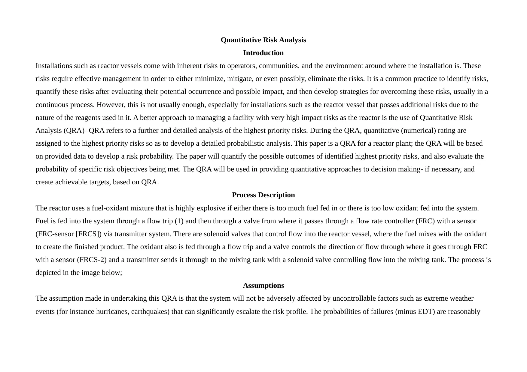
Quantitative Risk Analysis
Introduction
Installations such as reactor vessels come with inherent risks to operators, communities, and the environment around where the installation is. These
risks require effective management in order to either minimize, mitigate, or even possibly, eliminate the risks. It is a common practice to identify risks,
quantify these risks after evaluating their potential occurrence and possible impact, and then develop strategies for overcoming these risks, usually in a
continuous process. However, this is not usually enough, especially for installations such as the reactor vessel that posses additional risks due to the
nature of the reagents used in it. A better approach to managing a facility with very high impact risks as the reactor is the use of Quantitative Risk
Analysis (QRA)- QRA refers to a further and detailed analysis of the highest priority risks. During the QRA, quantitative (numerical) rating are
assigned to the highest priority risks so as to develop a detailed probabilistic analysis. This paper is a QRA for a reactor plant; the QRA will be based
on provided data to develop a risk probability. The paper will quantify the possible outcomes of identified highest priority risks, and also evaluate the
probability of specific risk objectives being met. The QRA will be used in providing quantitative approaches to decision making- if necessary, and
create achievable targets, based on QRA.
Process Description
The reactor uses a fuel-oxidant mixture that is highly explosive if either there is too much fuel fed in or there is too low oxidant fed into the system.
Fuel is fed into the system through a flow trip (1) and then through a valve from where it passes through a flow rate controller (FRC) with a sensor
(FRC-sensor [FRCS]) via transmitter system. There are solenoid valves that control flow into the reactor vessel, where the fuel mixes with the oxidant
to create the finished product. The oxidant also is fed through a flow trip and a valve controls the direction of flow through where it goes through FRC
with a sensor (FRCS-2) and a transmitter sends it through to the mixing tank with a solenoid valve controlling flow into the mixing tank. The process is
depicted in the image below;
Assumptions
The assumption made in undertaking this QRA is that the system will not be adversely affected by uncontrollable factors such as extreme weather
events (for instance hurricanes, earthquakes) that can significantly escalate the risk profile. The probabilities of failures (minus EDT) are reasonably
Paraphrase This Document
Need a fresh take? Get an instant paraphrase of this document with our AI Paraphraser
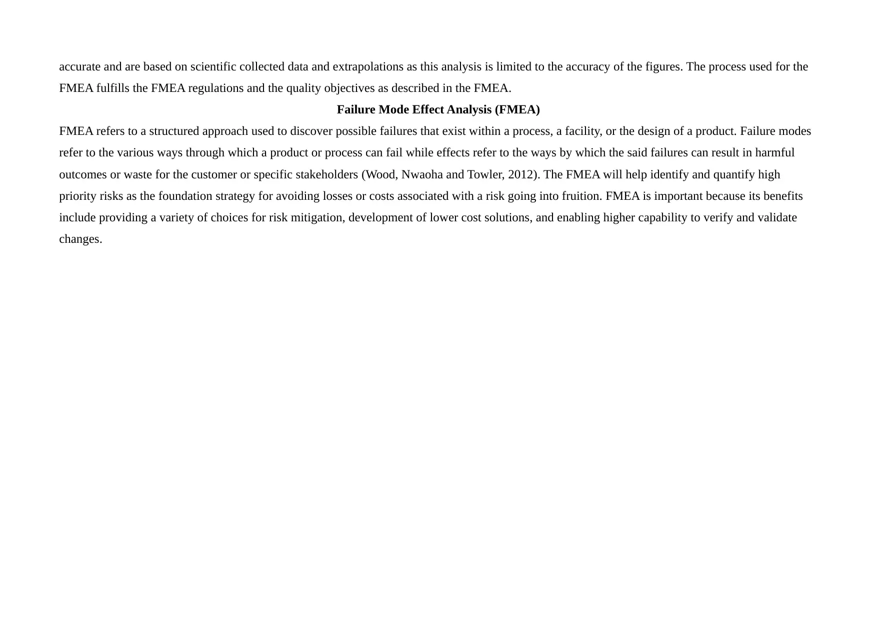
accurate and are based on scientific collected data and extrapolations as this analysis is limited to the accuracy of the figures. The process used for the
FMEA fulfills the FMEA regulations and the quality objectives as described in the FMEA.
Failure Mode Effect Analysis (FMEA)
FMEA refers to a structured approach used to discover possible failures that exist within a process, a facility, or the design of a product. Failure modes
refer to the various ways through which a product or process can fail while effects refer to the ways by which the said failures can result in harmful
outcomes or waste for the customer or specific stakeholders (Wood, Nwaoha and Towler, 2012). The FMEA will help identify and quantify high
priority risks as the foundation strategy for avoiding losses or costs associated with a risk going into fruition. FMEA is important because its benefits
include providing a variety of choices for risk mitigation, development of lower cost solutions, and enabling higher capability to verify and validate
changes.
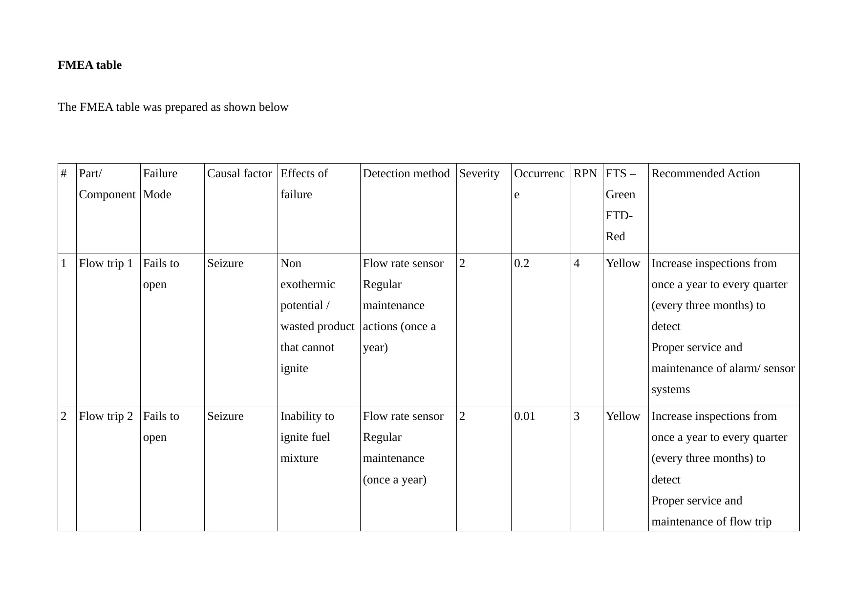
FMEA table
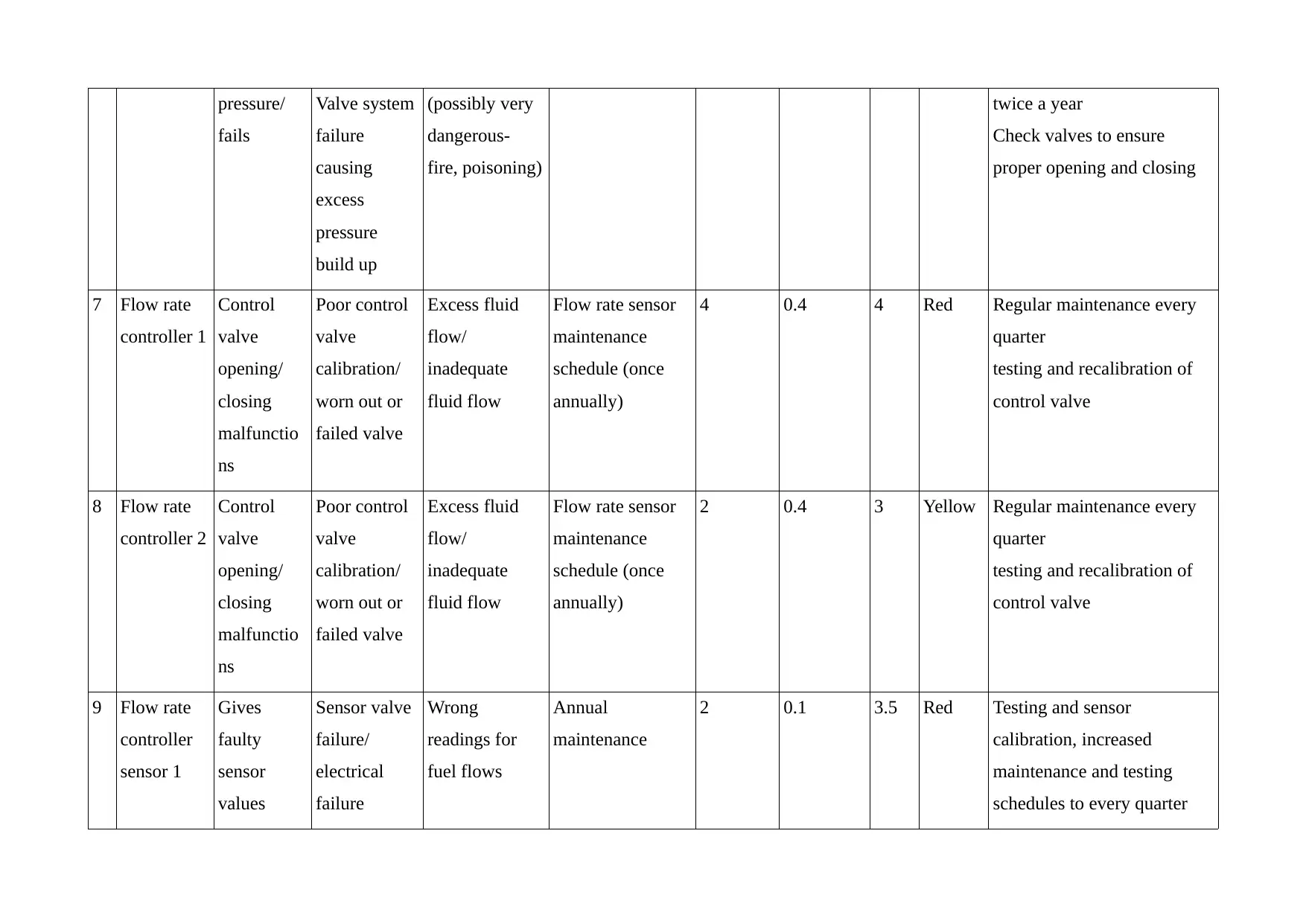
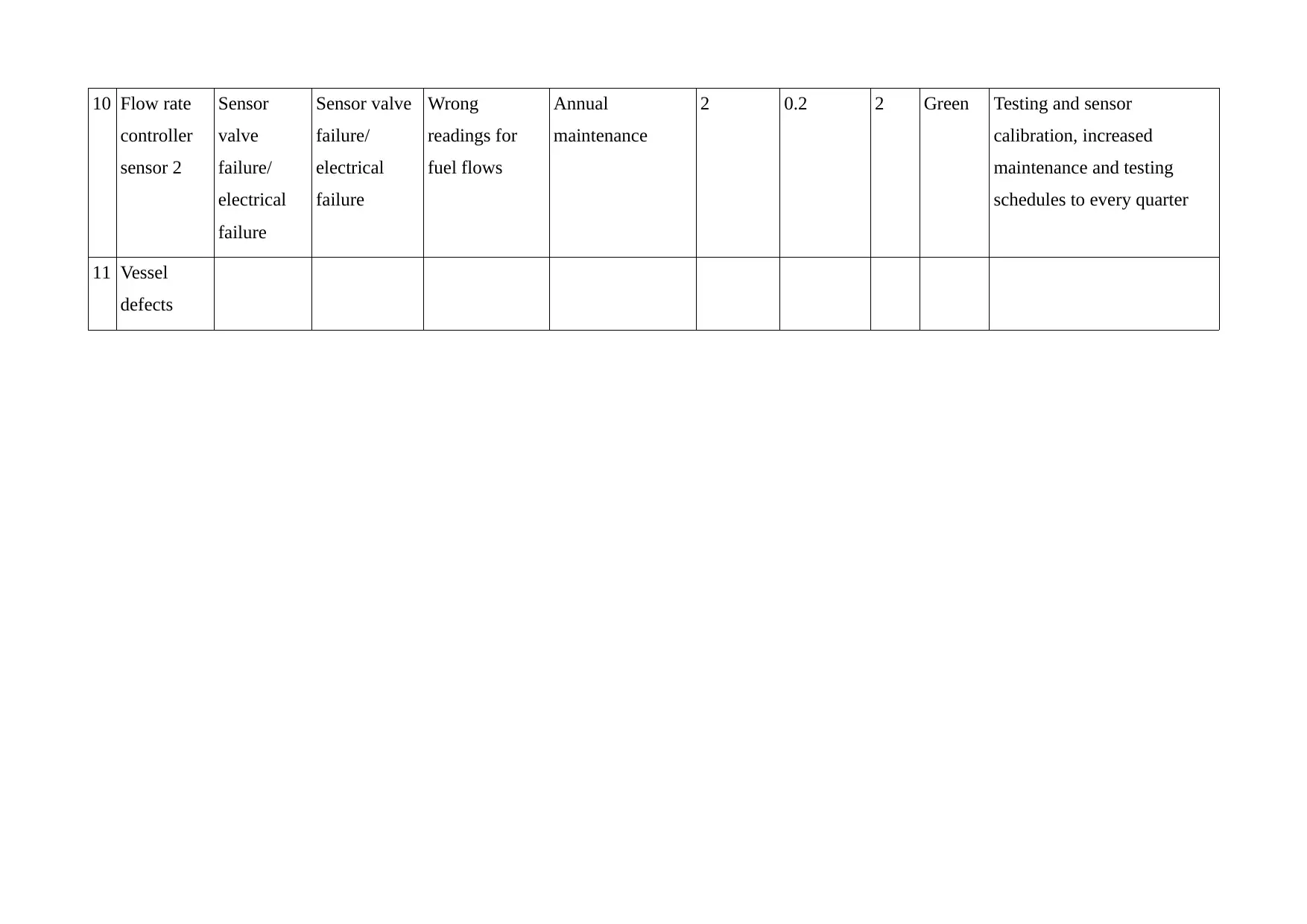
The FMEA table was prepared as shown below
# Part/
Component
Failure
Mode
Causal factor Effects of
failure
Detection method Severity Occurrenc
e
RPN FTS –
Green
FTD-
Red
Recommended Action
1 Flow trip 1 Fails to
open
Seizure Non
exothermic
potential /
wasted product
that cannot
ignite
Flow rate sensor
Regular
maintenance
actions (once a
year)
2 0.2 4 Yellow Increase inspections from
once a year to every quarter
(every three months) to
detect
Proper service and
maintenance of alarm/ sensor
systems
2 Flow trip 2 Fails to
open
Seizure Inability to
ignite fuel
mixture
Flow rate sensor
Regular
maintenance
(once a year)
2 0.01 3 Yellow Increase inspections from
once a year to every quarter
(every three months) to
detect
Proper service and
maintenance of flow trip
⊘ This is a preview!⊘
Do you want full access?
Subscribe today to unlock all pages.

Trusted by 1+ million students worldwide
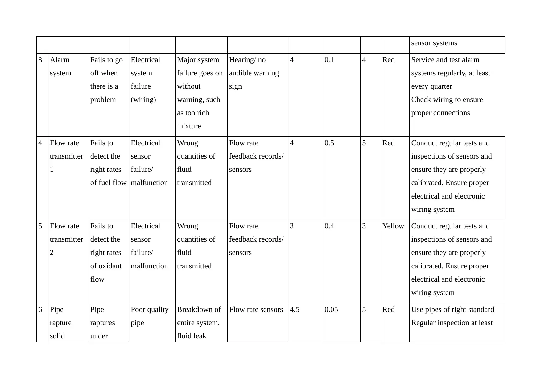
sensor systems
3 Alarm
system
Fails to go
off when
there is a
problem
Electrical
system
failure
(wiring)
Major system
failure goes on
without
warning, such
as too rich
mixture
Hearing/ no
audible warning
sign
4 0.1 4 Red Service and test alarm
systems regularly, at least
every quarter
Check wiring to ensure
proper connections
4 Flow rate
transmitter
1
Fails to
detect the
right rates
of fuel flow
Electrical
sensor
failure/
malfunction
Wrong
quantities of
fluid
transmitted
Flow rate
feedback records/
sensors
4 0.5 5 Red Conduct regular tests and
inspections of sensors and
ensure they are properly
calibrated. Ensure proper
electrical and electronic
wiring system
5 Flow rate
transmitter
2
Fails to
detect the
right rates
of oxidant
flow
Electrical
sensor
failure/
malfunction
Wrong
quantities of
fluid
transmitted
Flow rate
feedback records/
sensors
3 0.4 3 Yellow Conduct regular tests and
inspections of sensors and
ensure they are properly
calibrated. Ensure proper
electrical and electronic
wiring system
6 Pipe
rapture
solid
Pipe
raptures
under
Poor quality
pipe
Breakdown of
entire system,
fluid leak
Flow rate sensors 4.5 0.05 5 Red Use pipes of right standard
Regular inspection at least
Paraphrase This Document
Need a fresh take? Get an instant paraphrase of this document with our AI Paraphraser
pressure/
fails
Valve system
failure
causing
excess
pressure
build up
(possibly very
dangerous-
fire, poisoning)
twice a year
Check valves to ensure
proper opening and closing
7 Flow rate
controller 1
Control
valve
opening/
closing
malfunctio
ns
Poor control
valve
calibration/
worn out or
failed valve
Excess fluid
flow/
inadequate
fluid flow
Flow rate sensor
maintenance
schedule (once
annually)
4 0.4 4 Red Regular maintenance every
quarter
testing and recalibration of
control valve
8 Flow rate
controller 2
Control
valve
opening/
closing
malfunctio
ns
Poor control
valve
calibration/
worn out or
failed valve
Excess fluid
flow/
inadequate
fluid flow
Flow rate sensor
maintenance
schedule (once
annually)
2 0.4 3 Yellow Regular maintenance every
quarter
testing and recalibration of
control valve
9 Flow rate
controller
sensor 1
Gives
faulty
sensor
values
Sensor valve
failure/
electrical
failure
Wrong
readings for
fuel flows
Annual
maintenance
2 0.1 3.5 Red Testing and sensor
calibration, increased
maintenance and testing
schedules to every quarter
10 Flow rate
controller
sensor 2
Sensor
valve
failure/
electrical
failure
Sensor valve
failure/
electrical
failure
Wrong
readings for
fuel flows
Annual
maintenance
2 0.2 2 Green Testing and sensor
calibration, increased
maintenance and testing
schedules to every quarter
11 Vessel
defects
controller
sensor 2
Sensor
valve
failure/
electrical
failure
Sensor valve
failure/
electrical
failure
Wrong
readings for
fuel flows
Annual
maintenance
2 0.2 2 Green Testing and sensor
calibration, increased
maintenance and testing
schedules to every quarter
11 Vessel
defects
⊘ This is a preview!⊘
Do you want full access?
Subscribe today to unlock all pages.

Trusted by 1+ million students worldwide
Fault Tree
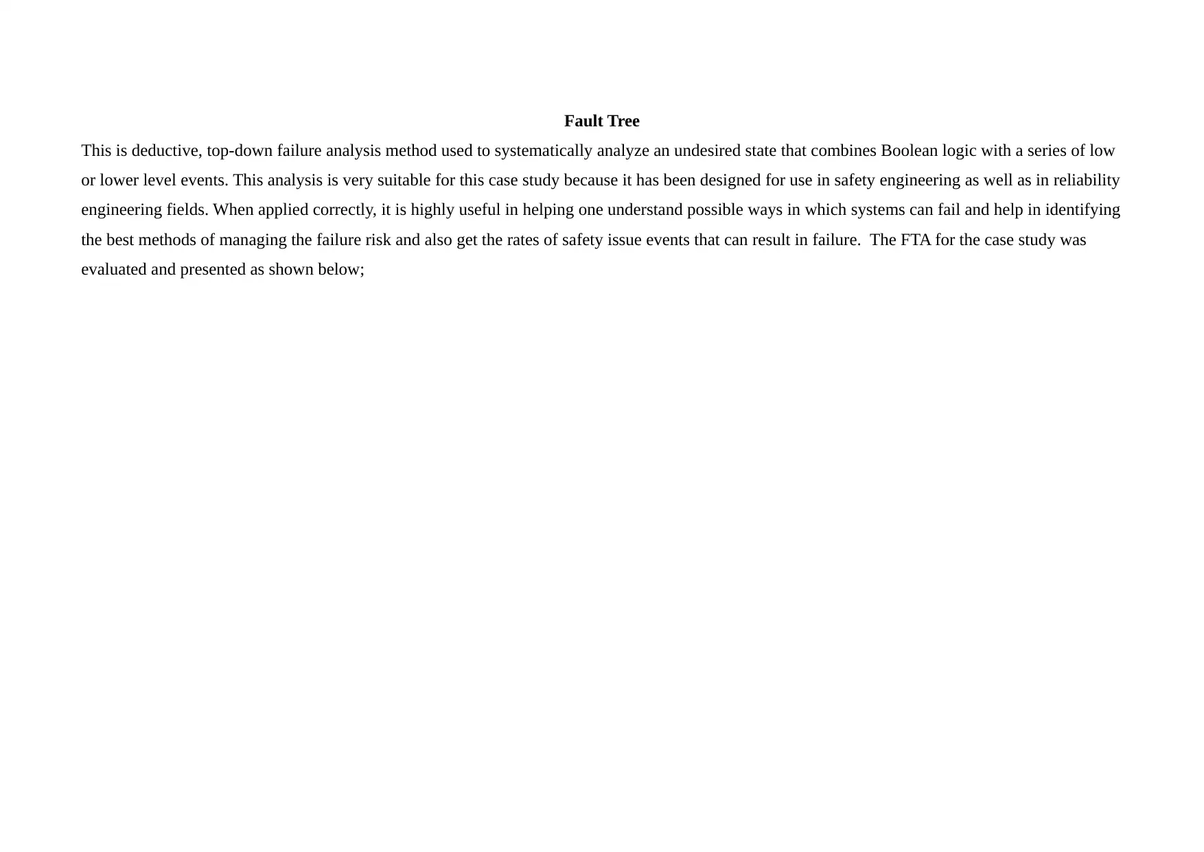
This is deductive, top-down failure analysis method used to systematically analyze an undesired state that combines Boolean logic with a series of low
or lower level events. This analysis is very suitable for this case study because it has been designed for use in safety engineering as well as in reliability
engineering fields. When applied correctly, it is highly useful in helping one understand possible ways in which systems can fail and help in identifying
the best methods of managing the failure risk and also get the rates of safety issue events that can result in failure. The FTA for the case study was
evaluated and presented as shown below;
Paraphrase This Document
Need a fresh take? Get an instant paraphrase of this document with our AI Paraphraser
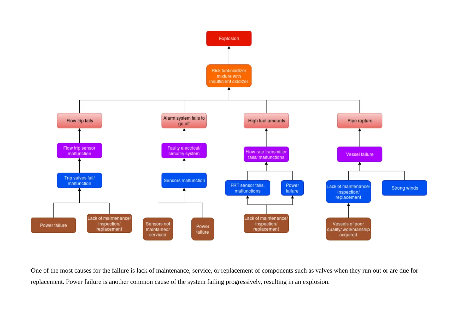
One of the most causes for the failure is lack of maintenance, service, or replacement of components such as valves when they run out or are due for
replacement. Power failure is another common cause of the system failing progressively, resulting in an explosion.
replacement. Power failure is another common cause of the system failing progressively, resulting in an explosion.
Expected Frequency of Explosion
The expected frequency refers to a probability count and is used in computing the standardized residuals by subtracting the expected count from
observed count. The observed frequencies/ counts refer to the counts that are made from data, such as experimental data or from observations. This
implies that there is actual observation of occurrences and records are taken for their frequency, or advanced algorithms used to generate them. The
expected frequencies refer to the counts computed based on the probability theory. The probability theory enables the analysis of events that can occur
because of chance in a manner that is logically sound.
Event tree Analysis – Top Event Consequence
This was prepared with the probabilities computed as shown below;
⊘ This is a preview!⊘
Do you want full access?
Subscribe today to unlock all pages.

Trusted by 1+ million students worldwide
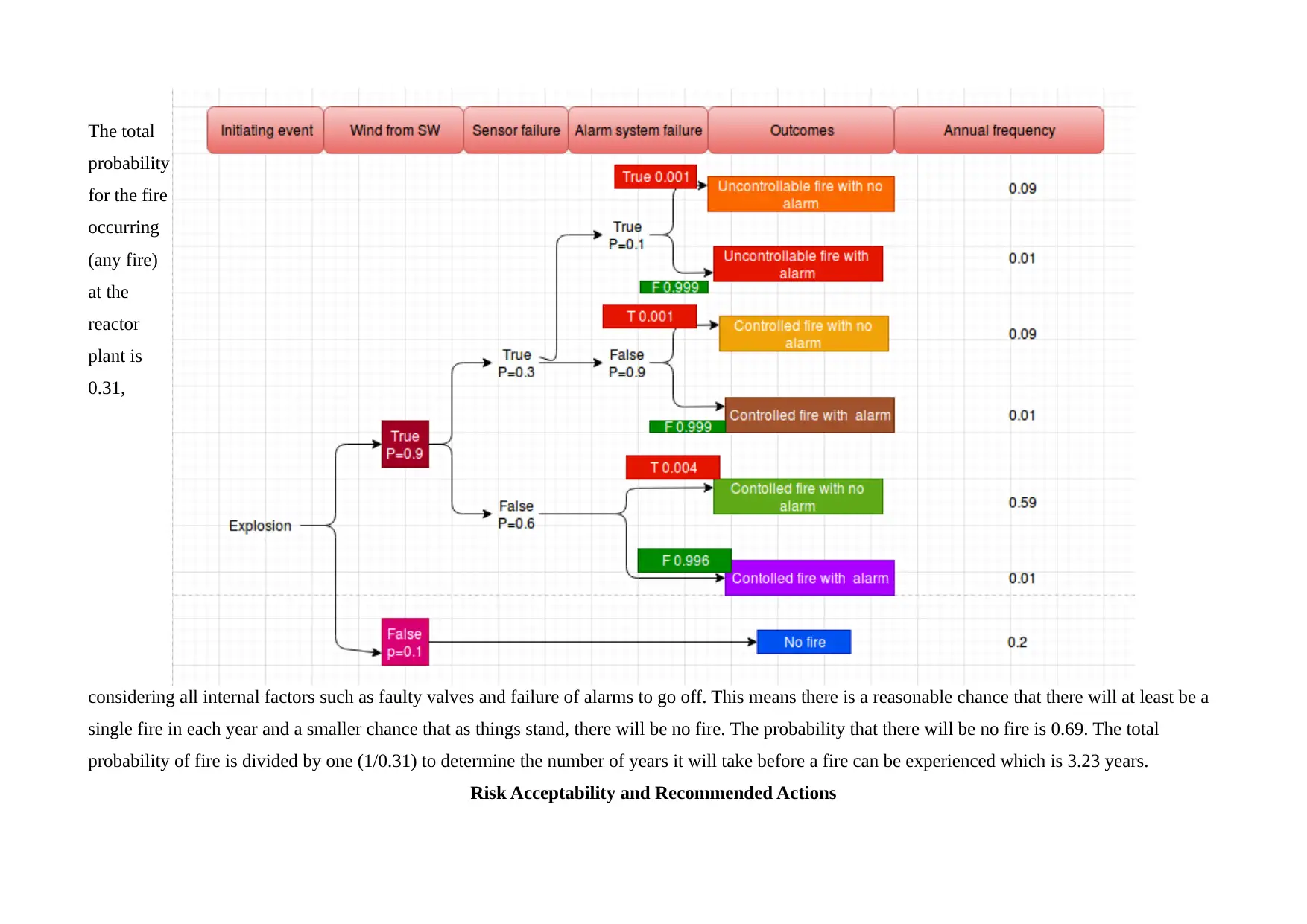
The total
probability
for the fire
occurring
(any fire)
at the
reactor
plant is
0.31,
considering all internal factors such as faulty valves and failure of alarms to go off. This means there is a reasonable chance that there will at least be a
single fire in each year and a smaller chance that as things stand, there will be no fire. The probability that there will be no fire is 0.69. The total
probability of fire is divided by one (1/0.31) to determine the number of years it will take before a fire can be experienced which is 3.23 years.
Risk Acceptability and Recommended Actions
Paraphrase This Document
Need a fresh take? Get an instant paraphrase of this document with our AI Paraphraser
The risk analysis, based on the FMEA, the fault tree and the event tree analysis in which gave probabilities shows that as it is with the current
probabilities of failure in the various components that make up the reactor system (the valves, sensors, power failure, alarm system), it will take at least
3.3 years before a fire incident can be reported. The severity of such an occurrence can be catastrophic though, since there is a large human population
nearby and there is an external weather factor (wind), that can provide an enabling environment for a devastating fire. However, there risks can be
controlled. Controlling a risk implies either mitigating the effects of the risks, or reducing them through a series of actions (Sreeram and Thondiyath,
2015). For this case, the risk profile and the probability of failures resulting to a fire mean that mitigating measures can easily minimize the probability
of a fire.
Actions to Mitigate Risks
The first step is prevention through improved management of the maintenance and testing of the various components ; the maintenance and inspection
frequencies should be increased from once a year to every quarter where the critical components that include the valves, control valves, flow control
systems, sensors, alarms, and solenoid valves, as well as electrical systems are frequently inspected and checked. By doing this, possible faults can be
detected upfront and the component changed or serviced. Testing sensors under different load conditions will also help ensure they are in good working
condition and flow rate sensors work properly. When this is done, in addition to quality management systems incorporated at the initial stages,
including getting the highest quality parts and components, having high quality metrics during inspections or testing, frequent testing, and coupled with
effective risk management plans, the probability of a fire can be further reduced to < 0.02, which would effectively increase the number of years before
a fire can be expected to fifty years.
References
Sreeram, T. and Thondiyath, A. (2015). Combining Lean and Six Sigma in the context of Systems Engineering design. International Journal of Lean
Six Sigma, 6(4), pp.290-312.
Wood, D., Nwaoha, C. and Towler, B. (2012). Gas-to-liquids (GTL): A review of an industry offering several routes for monetizing natural gas.
Journal of Natural Gas Science and Engineering, 9, pp.196-208.
⊘ This is a preview!⊘
Do you want full access?
Subscribe today to unlock all pages.

Trusted by 1+ million students worldwide
1 out of 12
Your All-in-One AI-Powered Toolkit for Academic Success.
+13062052269
info@desklib.com
Available 24*7 on WhatsApp / Email
![[object Object]](/_next/static/media/star-bottom.7253800d.svg)
Unlock your academic potential
Copyright © 2020–2026 A2Z Services. All Rights Reserved. Developed and managed by ZUCOL.
