Block Diagrams of Current Control Methods for Vector Control of AC Machines

Verified

Added on  2023/03/30

|5
|912
|129
AI Summary
This article presents the block diagrams of three current control methods for vector control of AC machines: Three-phase Hysteresis control, Stationary-Frame PI control, and Synchronous-Frame PI control. The merits and demerits of each method are described separately. The article also discusses the mathematical model of a Permanent Magnet Synchronous Machine (PMSM) and provides calculations for deriving base values and per unit machine parameters for building a vector control scheme for the PMSM. Additionally, the article explains the dynamic model of the PMSM in a synchronous frame (dq frame) and includes a block diagram of the model. Finally, it mentions various topics related to PMSM control, such as decoupling, Simulink, internal model approach, closed loop, speed control, and using Simulink for demonstration.

Contribute Materials

Your contribution can guide someone’s learning journey. Share your documents today.
Document Page
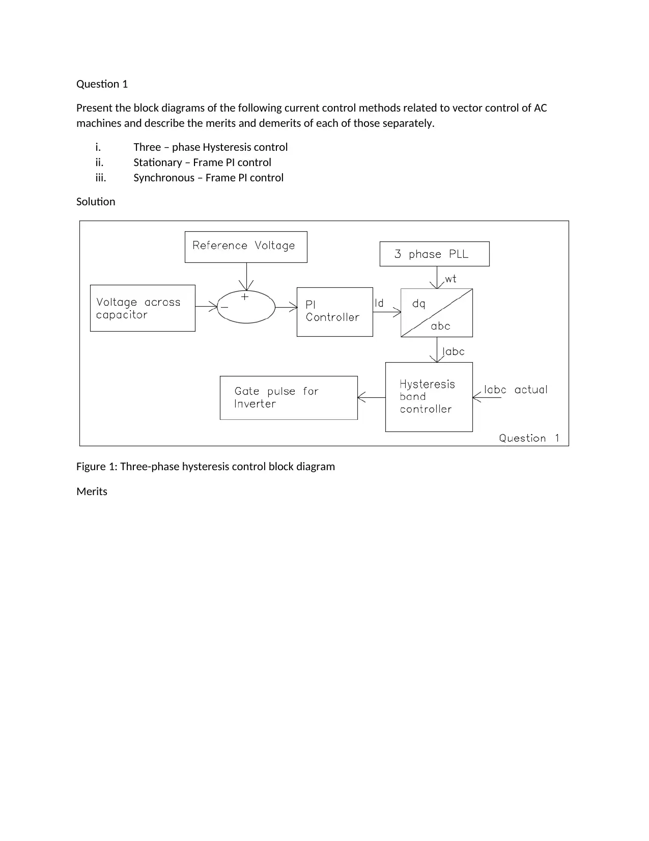
Question 1
Present the block diagrams of the following current control methods related to vector control of AC
machines and describe the merits and demerits of each of those separately.
i. Three – phase Hysteresis control
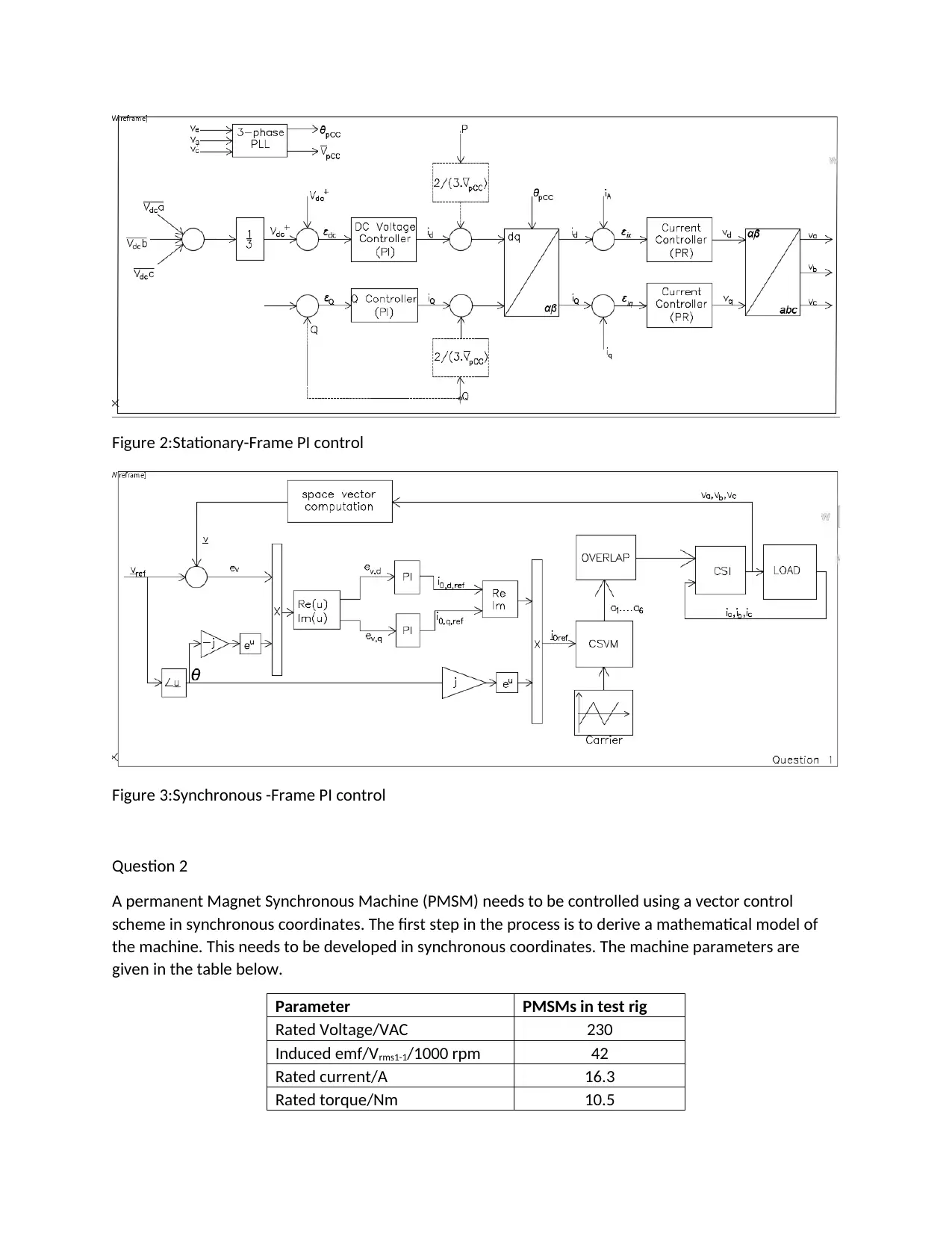
ii. Stationary – Frame PI control
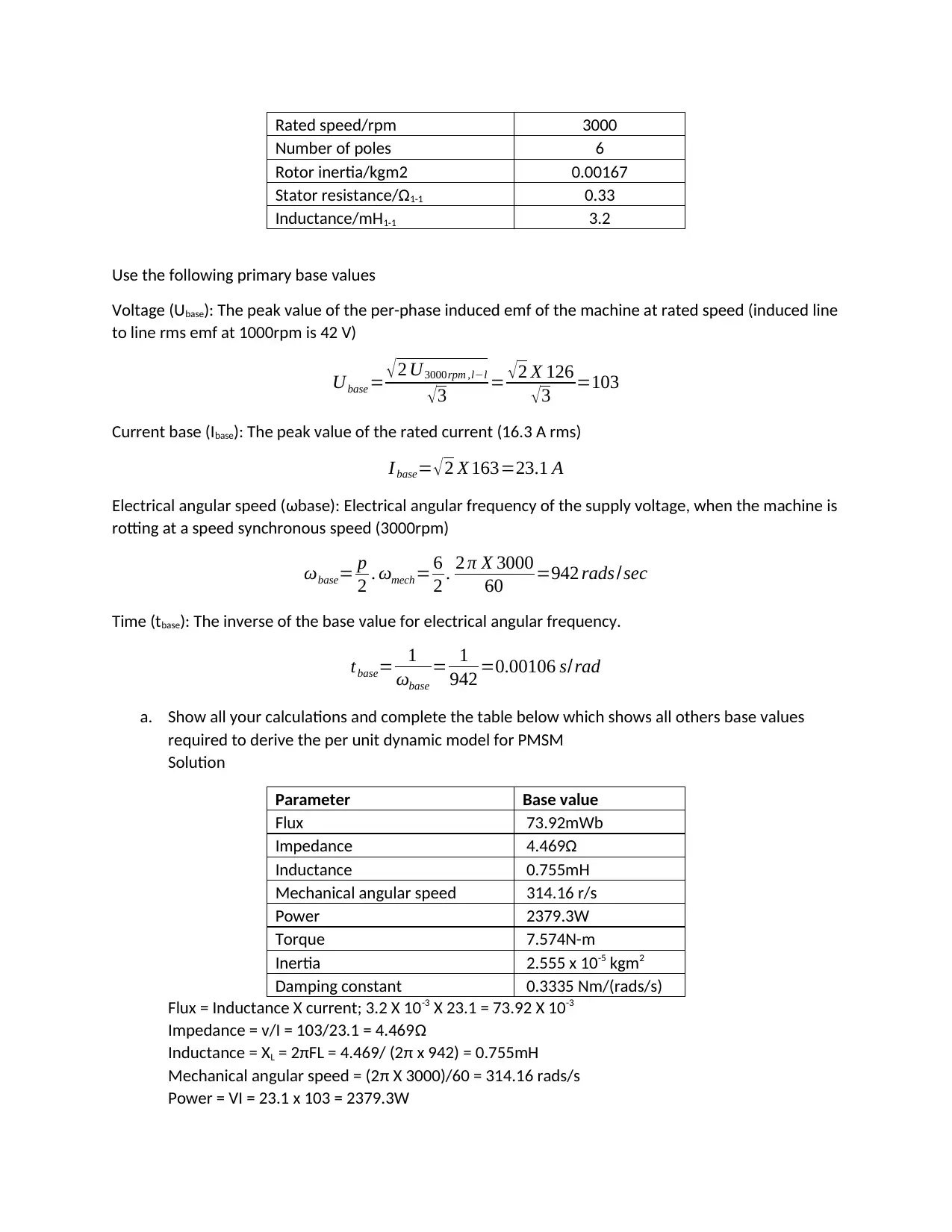
iii. Synchronous – Frame PI control
Solution
Figure 1: Three-phase hysteresis control block diagram
Merits

Secure Best Marks with AI Grader

Need help grading? Try our AI Grader for instant feedback on your assignments.
Document Page
Figure 2:Stationary-Frame PI control
Figure 3:Synchronous -Frame PI control
Question 2
A permanent Magnet Synchronous Machine (PMSM) needs to be controlled using a vector control
scheme in synchronous coordinates. The first step in the process is to derive a mathematical model of
the machine. This needs to be developed in synchronous coordinates. The machine parameters are
given in the table below.
Parameter PMSMs in test rig
Rated Voltage/VAC 230
Induced emf/Vrms1-1/1000 rpm 42
Rated current/A 16.3
Rated torque/Nm 10.5
Document Page
Rated speed/rpm 3000
Number of poles 6
Rotor inertia/kgm2 0.00167
Stator resistance/Ω1-1 0.33
Inductance/mH1-1 3.2
Use the following primary base values
Voltage (Ubase): The peak value of the per-phase induced emf of the machine at rated speed (induced line
to line rms emf at 1000rpm is 42 V)
Ubase = 2 U3000rpm ,ll
3 = 2 X 126
3 =103
Current base (Ibase): The peak value of the rated current (16.3 A rms)
I base= 2 X 163=23.1 A
Electrical angular speed (ωbase): Electrical angular frequency of the supply voltage, when the machine is
rotting at a speed synchronous speed (3000rpm)
ωbase= p
2 . ωmech= 6
2 . 2 π X 3000
60 =942 rads /sec
Time (tbase): The inverse of the base value for electrical angular frequency.
tbase= 1
ωbase
= 1
942 =0.00106 s/rad
a. Show all your calculations and complete the table below which shows all others base values
required to derive the per unit dynamic model for PMSM
Solution
Parameter Base value
Flux 73.92mWb
Impedance 4.469Ω
Inductance 0.755mH
Mechanical angular speed 314.16 r/s
Power 2379.3W
Torque 7.574N-m
Inertia 2.555 x 10⁻⁵ kgm2
Damping constant 0.3335 Nm/(rads/s)
Flux = Inductance X current; 3.2 X 10-3 X 23.1 = 73.92 X 10⁻³
Impedance = v/I = 103/23.1 = 4.469Ω
Inductance = XL = 2πFL = 4.469/ (2π x 942) = 0.755mH
Mechanical angular speed = (2π X 3000)/60 = 314.16 rads/s
Power = VI = 23.1 x 103 = 2379.3W
Document Page
Torque = power/angular speed = 2379.3/314.16 = 7.574N-m
Acceleration = ω/t = (314.16 x 10⁵)/106 = 2.964 x 10⁵. Inertia = torque/acceleration =
7.574/2.964 = 2.555 x 10⁻⁵N
Damping ratio shall be = mechanical angular speed/ Electrical angular speed= 314.16/942 =
0.3335
b. Sow all per unit calculations and complete the table below which shows all per unit machine
parameters required to build the vector control scheme for the PMSM
Parameter Actual value per-unit value
Ld 1.6mH 2.12mH
Lq (Assumed to be 5% higher than Ld) 1.68mH 2.12mH
Rs 0.1663Ω 0.0372Ω
ψm 0.109Wb 1.475Wb
Total inertia 4.209 X 10⁻³ kgm2 164.74kgm2
Damping 0.00456Nm/(rads/s)
0.01369 Nm/(rads/s)
Per unit value = actual value/ base value
Inductance = 1.6/0.755 = 2.119mH
0.755 x 1.05 = 0.79275,
Lq= 1.68/0.79275 = 2.119mH
Rs = 0.1663/4.469 = 0.0372Ω
ψm = (0.109 x 10³)/73.92 = 1.475Wb
Inertia = (4.209 x 10⁻³)/(2.555 x 10-5) = 164.74kgm2
Damping = 0.00456/0.333 = 0.01369 Nm/(rads/s)
Question 3
a. Deriving the dynamic model of the PMSM in a synchronous frame (dq frame)
PMSMs is usually used for industrial drives and are normally controlled via closed-loop. The
three phase PMSM is changed to a d – q – 0 frame reference. A complete balanced voltage
equation that are in the reference frame of d-q, are as follows:
ud =Rid + ψd
id
did
dt + ψd
iq
diq
dt + ψ
θ

dt ψq

d ..(1)
uq =Riq + ψq
iq
diq
dt + ψq
id
did
dt + ψ
θ

dt ψd

d ..(2)
Where ψd and ψq are flux linkages of the direct and quadrature-axis flux linkages respectively.
Therefore, the flux linkages associated with the permanent magnet, id and iq are the references
frame currents of d – q, R is the resistance from the stator, θ is the position of the rotor with
respect to the stator. The equation for the rotation can be added and the one describing the
subsystem of mechanical is:
J d2 θ
d t2 = p T em
2 ( id ,iq , θ ) T lT trw (3)

Secure Best Marks with AI Grader

Need help grading? Try our AI Grader for instant feedback on your assignments.
Document Page
Where, J is the inertia of the rotor, Tl and Ttrw are the frictional torque and load torque, Tem is the
torque that results from the electromagnet.
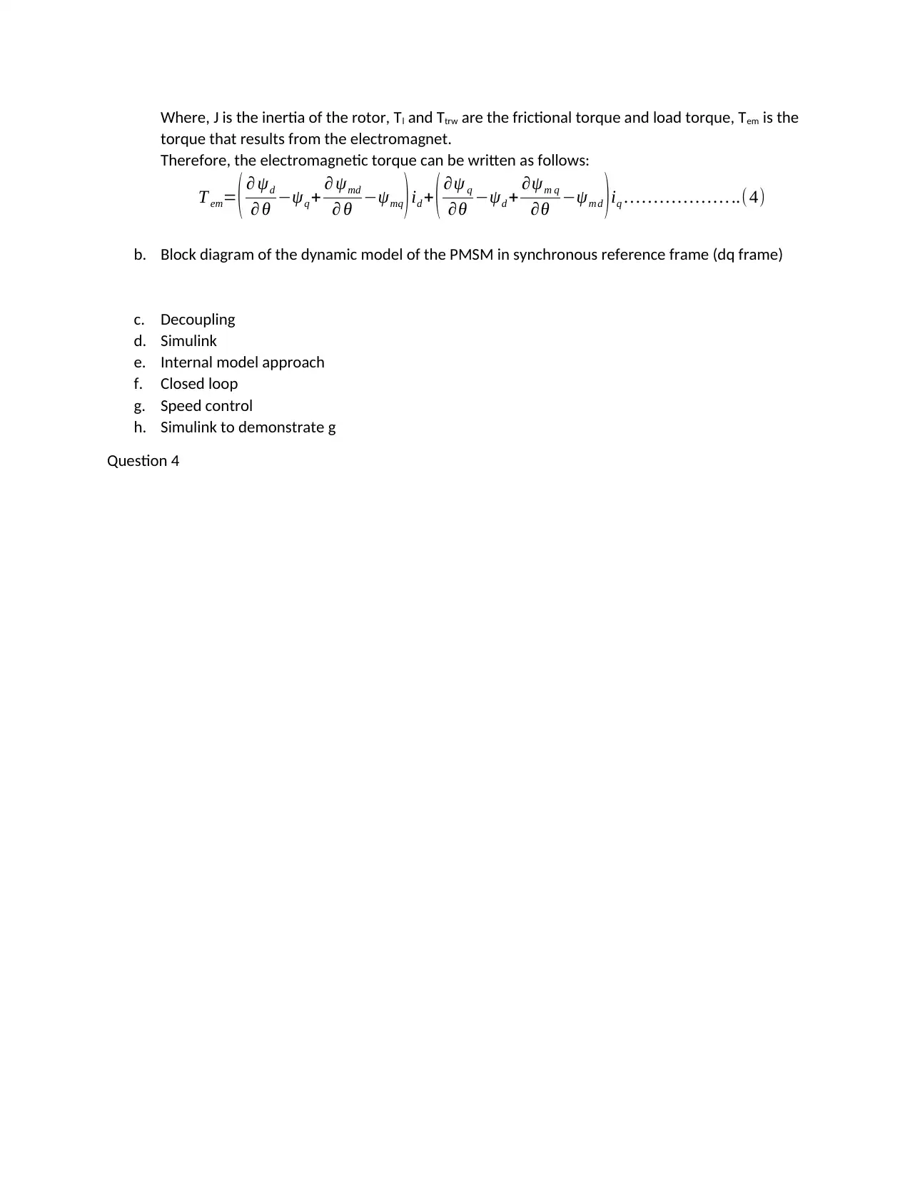
Therefore, the electromagnetic torque can be written as follows:
T em= ( ψd
θ ψq + ψmd
θ ψmq )id + ( ψ q
θ ψd + ψm q
θ ψm d )iq ..(4)
b. Block diagram of the dynamic model of the PMSM in synchronous reference frame (dq frame)
c. Decoupling
d. Simulink
e. Internal model approach
f. Closed loop
g. Speed control
h. Simulink to demonstrate g
Question 4
1 out of 5
circle_padding
hide_on_mobile
zoom_out_icon
[object Object]

Your All-in-One AI-Powered Toolkit for Academic Success.

Available 24*7 on WhatsApp / Email

[object Object]