Network Design and Analysis: Cellular Architecture and Cell Splitting
VerifiedAdded on 2023/01/23
|9
|1649
|65
Homework Assignment
AI Summary
This assignment solution addresses key concepts in cellular network design and wireless communication. It begins by explaining cell splitting with diagrams and its impact on capacity. The solution then calculates the reuse distance, the number of simultaneous calls, and the Erlang value for a given cellular system. The core of the assignment involves a network design proposal, where the student proposes a cellular architecture based on the micro cell concept, detailing base station locations, antenna specifications, and area type considerations (urban, suburban, rural). The design utilizes a hexagonal cell layout and justifies the design choices. The solution also explains the reasoning behind the chosen cellular architecture, highlighting the advantages of hexagonal cells and frequency reuse. The assignment incorporates relevant formulas and calculations to illustrate the principles of cellular network design.
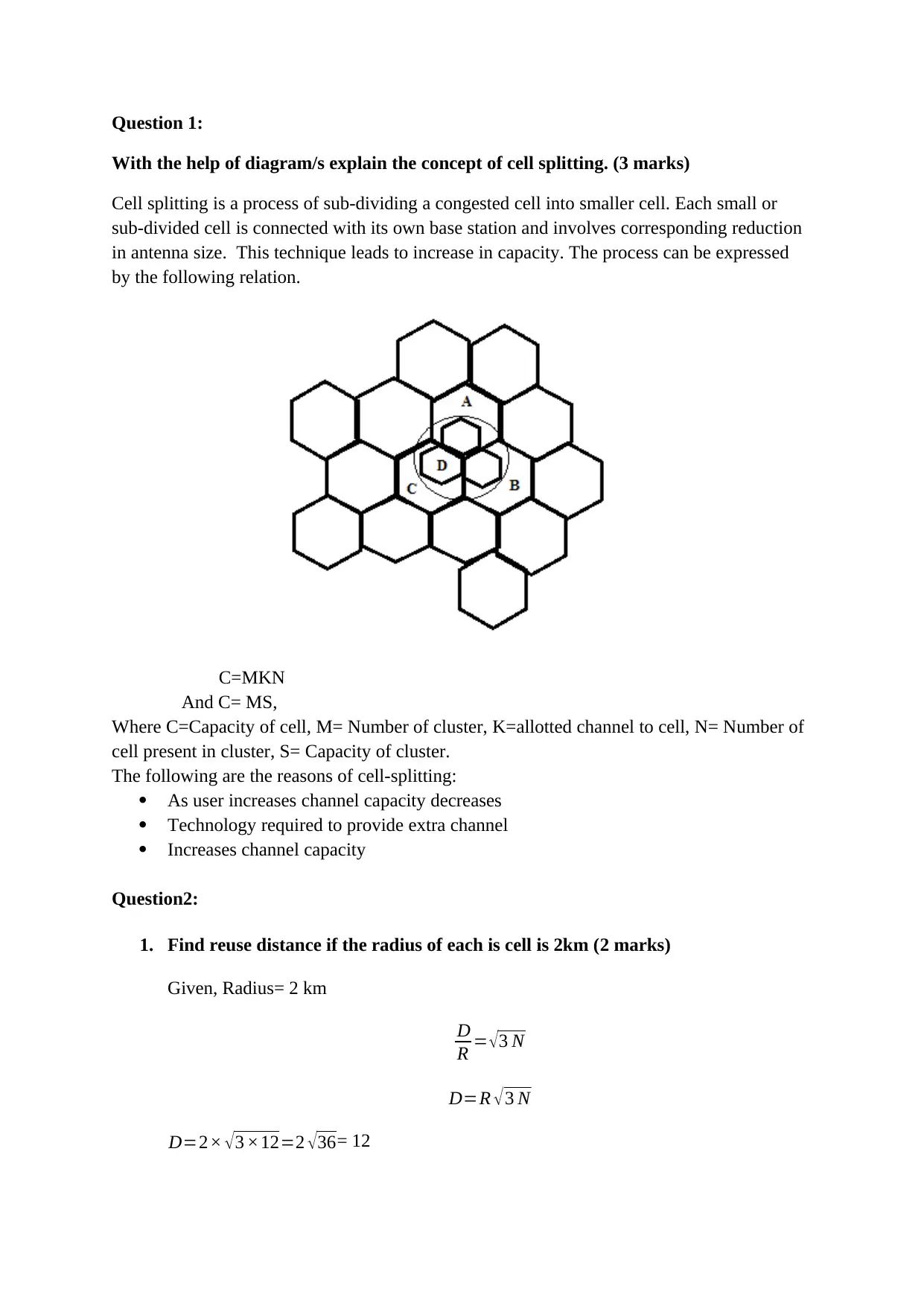
Question 1:
With the help of diagram/s explain the concept of cell splitting. (3 marks)
Cell splitting is a process of sub-dividing a congested cell into smaller cell. Each small or
sub-divided cell is connected with its own base station and involves corresponding reduction
in antenna size. This technique leads to increase in capacity. The process can be expressed
by the following relation.
C=MKN
And C= MS,
Where C=Capacity of cell, M= Number of cluster, K=allotted channel to cell, N= Number of
cell present in cluster, S= Capacity of cluster.
The following are the reasons of cell-splitting:
As user increases channel capacity decreases
Technology required to provide extra channel
Increases channel capacity
Question2:
1. Find reuse distance if the radius of each is cell is 2km (2 marks)
Given, Radius= 2 km
D
R = √ 3 N
D=R √ 3 N
D=2× √3 ×12=2 √36= 12
Paraphrase This Document
Need a fresh take? Get an instant paraphrase of this document with our AI Paraphraser
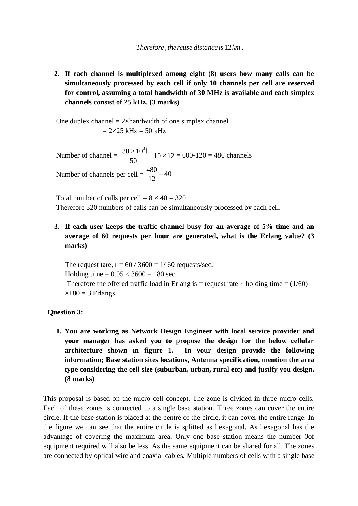
Therefore , thereuse distance is 12km .
2. If each channel is multiplexed among eight (8) users how many calls can be
simultaneously processed by each cell if only 10 channels per cell are reserved
for control, assuming a total bandwidth of 30 MHz is available and each simplex
channels consist of 25 kHz. (3 marks)
One duplex channel = 2×bandwidth of one simplex channel
= 2×25 kHz = 50 kHz
Number of channel = ( 30 ×103 )
50 −10 ×12 = 600-120 = 480 channels
Number of channels per cell = 480
12 =40
Total number of calls per cell = 8 × 40 = 320
Therefore 320 numbers of calls can be simultaneously processed by each cell.
3. If each user keeps the traffic channel busy for an average of 5% time and an
average of 60 requests per hour are generated, what is the Erlang value? (3
marks)
The request tare, r = 60 / 3600 = 1/ 60 requests/sec.
Holding time = 0.05 × 3600 = 180 sec
Therefore the offered traffic load in Erlang is = request rate × holding time = (1/60)
×180 = 3 Erlangs
Question 3:
1. You are working as Network Design Engineer with local service provider and
your manager has asked you to propose the design for the below cellular
architecture shown in figure 1. In your design provide the following
information; Base station sites locations, Antenna specification, mention the area
type considering the cell size (suburban, urban, rural etc) and justify you design.
(8 marks)
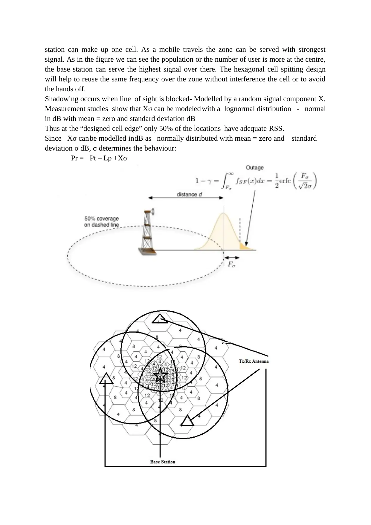
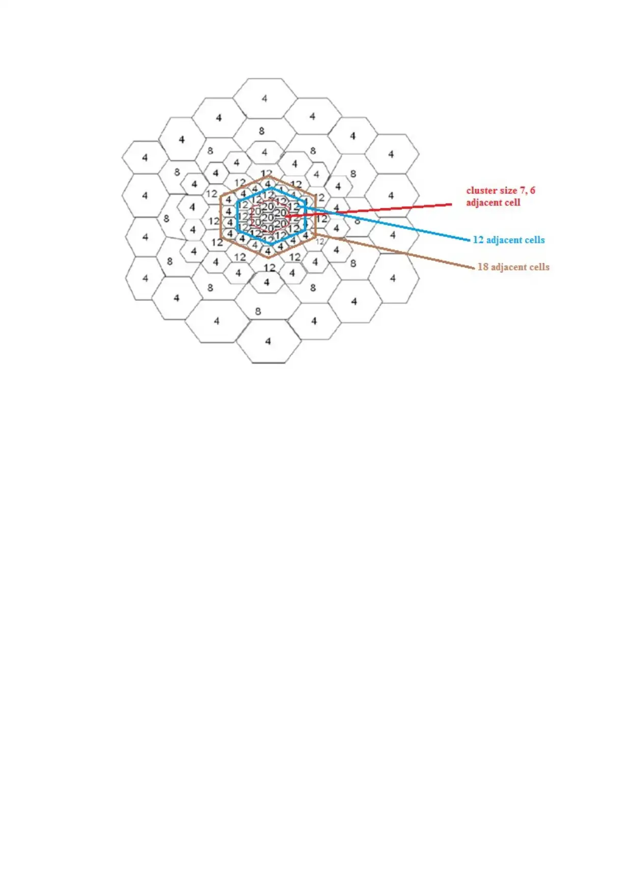
This proposal is based on the micro cell concept. The zone is divided in three micro cells.
Each of these zones is connected to a single base station. Three zones can cover the entire
circle. If the base station is placed at the centre of the circle, it can cover the entire range. In
the figure we can see that the entire circle is splitted as hexagonal. As hexagonal has the
advantage of covering the maximum area. Only one base station means the number 0of
equipment required will also be less. As the same equipment can be shared for all. The zones
are connected by optical wire and coaxial cables. Multiple numbers of cells with a single base
station can make up one cell. As a mobile travels the zone can be served with strongest
signal. As in the figure we can see the population or the number of user is more at the centre,
the base station can serve the highest signal over there. The hexagonal cell spitting design
will help to reuse the same frequency over the zone without interference the cell or to avoid
the hands off.
Shadowing occurs when line of sight is blocked- Modelled by a random signal component X.
Measurement studies show that Xσ can be modeled with a lognormal distribution - normal
in dB with mean = zero and standard deviation dB
Thus at the “designed cell edge” only 50% of the locations have adequate RSS.
Since Xσ can be modelled indB as normally distributed with mean = zero and standard
deviation σ dB, σ determines the behaviour:
Pr = Pt – Lp +Xσ
⊘ This is a preview!⊘
Do you want full access?
Subscribe today to unlock all pages.

Trusted by 1+ million students worldwide
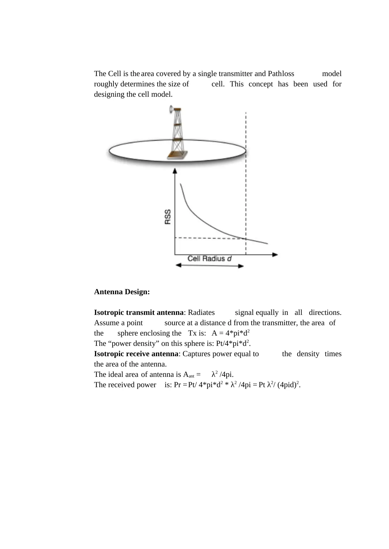
The Cell is the area covered by a single transmitter and Pathloss model
roughly determines the size of cell. This concept has been used for
designing the cell model.
Antenna Design:
Isotropic transmit antenna: Radiates signal equally in all directions.
Assume a point source at a distance d from the transmitter, the area of
the sphere enclosing the Tx is: A = 4*pi*d2
The “power density” on this sphere is: Pt/4*pi*d2.
Isotropic receive antenna: Captures power equal to the density times
the area of the antenna.
The ideal area of antenna is Aant = λ2 /4pi.
The received power is: Pr = Pt/ 4*pi*d2 * λ2 /4pi = Pt λ2/ (4pid)2.
Paraphrase This Document
Need a fresh take? Get an instant paraphrase of this document with our AI Paraphraser
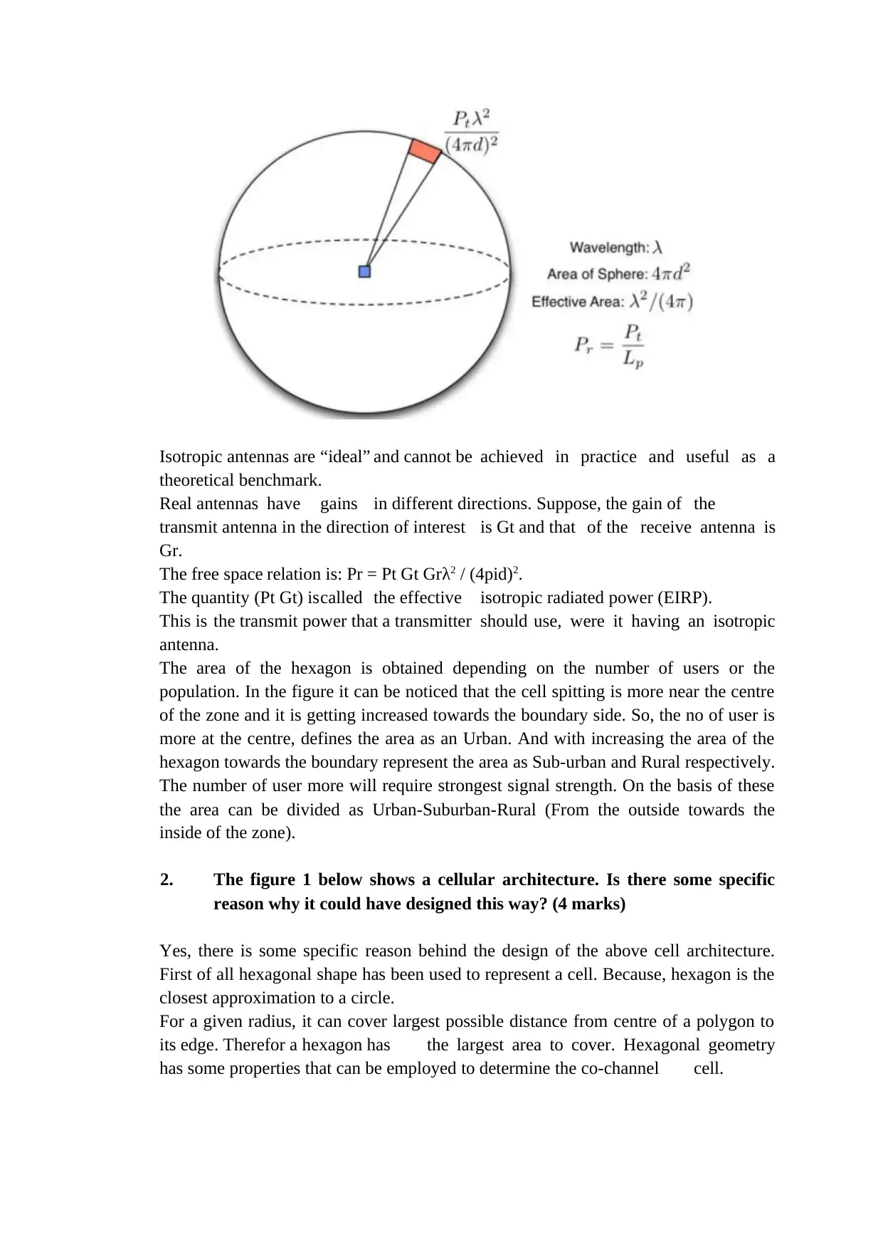
Isotropic antennas are “ideal” and cannot be achieved in practice and useful as a
theoretical benchmark.
Real antennas have gains in different directions. Suppose, the gain of the
transmit antenna in the direction of interest is Gt and that of the receive antenna is
Gr.
The free space relation is: Pr = Pt Gt Grλ2 / (4pid)2.
The quantity (Pt Gt) iscalled the effective isotropic radiated power (EIRP).
This is the transmit power that a transmitter should use, were it having an isotropic
antenna.
The area of the hexagon is obtained depending on the number of users or the
population. In the figure it can be noticed that the cell spitting is more near the centre
of the zone and it is getting increased towards the boundary side. So, the no of user is
more at the centre, defines the area as an Urban. And with increasing the area of the
hexagon towards the boundary represent the area as Sub-urban and Rural respectively.
The number of user more will require strongest signal strength. On the basis of these
the area can be divided as Urban-Suburban-Rural (From the outside towards the
inside of the zone).
2. The figure 1 below shows a cellular architecture. Is there some specific
reason why it could have designed this way? (4 marks)
Yes, there is some specific reason behind the design of the above cell architecture.
First of all hexagonal shape has been used to represent a cell. Because, hexagon is the
closest approximation to a circle.
For a given radius, it can cover largest possible distance from centre of a polygon to
its edge. Therefor a hexagon has the largest area to cover. Hexagonal geometry
has some properties that can be employed to determine the co-channel cell.
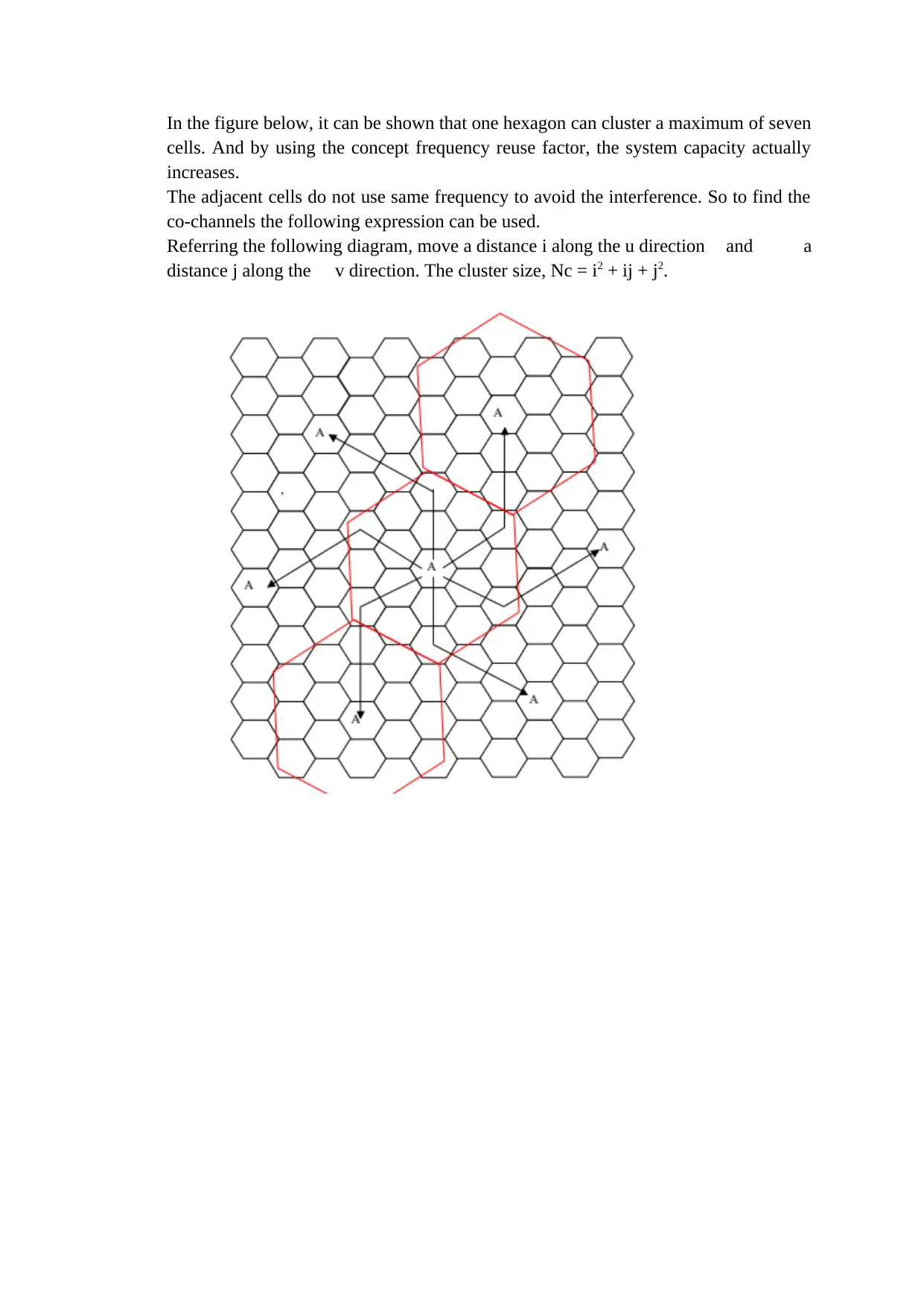
In the figure below, it can be shown that one hexagon can cluster a maximum of seven
cells. And by using the concept frequency reuse factor, the system capacity actually
increases.
The adjacent cells do not use same frequency to avoid the interference. So to find the
co-channels the following expression can be used.
Referring the following diagram, move a distance i along the u direction and a
distance j along the v direction. The cluster size, Nc = i2 + ij + j2.
⊘ This is a preview!⊘
Do you want full access?
Subscribe today to unlock all pages.

Trusted by 1+ million students worldwide
Paraphrase This Document
Need a fresh take? Get an instant paraphrase of this document with our AI Paraphraser
Reference:
Anitha, J. (2015). 4G Mobile Communications - Emerging Technologies. Research
Gate. Retrieved from
https://www.researchgate.net/publication/292154567_4G_Mobile_Communications_-
_Emerging_Technologies.
Campbell, S. W. (2017). Mobile Communication and Network Privatism: A Literature
Review of the Implications for Diverse, Weak, and New Ties. Review of
Communication Research. 3(1).
Chidiebere, C. I., Omijeh, B. O., (2018). Reduction of Co-Channel Interference In
Cellular Network Using Sectorization Method. American Journal of Engineering
Research. 7 (10). 204-218.
Ghosh, A. (2015). Cell Splitting and Sectoring. Retrieved from https://prezi.com/6c-
r7rbnv9s7/cell-splitting-and-sectoring/
Gupta, S. (2013). Cell splitting and sectoring in cell phones. Retrieved from
https://www.slideshare.net/shwetagupta796/cell-splitting-and-sectoring.
Hillebrand, F. (2013). The creation of standards for global mobile communication:
GSM and UMTS standardization from 1982 to 2000. IEEE Wireless Communications
20 (5) 23-33.
Jensen, K. B. (2013). What’s mobile in mobile communication? Mobile Media and
Communications.
Ohaneme C.O., Onoh G.N., Ifeagwu E.N., Eneh I.I. (2012). Improving Channel
Capacity of A Cellular System Using Cell Splitting 1. International Journal of Science
Engineering and Research.
Pisarody, M. (2013). Cell Splitting: Mobile Computing. Retrieved from
http://www.itportal.in/2012/11/cell-splitting-mobile-computing-be.html
Stuber, Gordon, L. (2017). Principles of Mobile Communication. Signals and
Communications.
Vashudevan, A. (2019). Cell Splitting. Retrieved from
https://www.scribd.com/document/97208483/Cell-Splitting
Zhang, Z., Wu, L., Dang, J. (2017). Optical mobile communications: Principles and
challenges. 26th Wireless and Optical fibre Communication Conference. Newark, NJ,
USA.
challenges. 26th Wireless and Optical fibre Communication Conference. Newark, NJ,
USA.
⊘ This is a preview!⊘
Do you want full access?
Subscribe today to unlock all pages.

Trusted by 1+ million students worldwide
1 out of 9
Related Documents
Your All-in-One AI-Powered Toolkit for Academic Success.
+13062052269
info@desklib.com
Available 24*7 on WhatsApp / Email
![[object Object]](/_next/static/media/star-bottom.7253800d.svg)
Unlock your academic potential
Copyright © 2020–2025 A2Z Services. All Rights Reserved. Developed and managed by ZUCOL.


