Communication Engineering Module: CommSim Modulation Experiment Report
VerifiedAdded on 2023/04/21
|15
|1595
|434
Practical Assignment
AI Summary
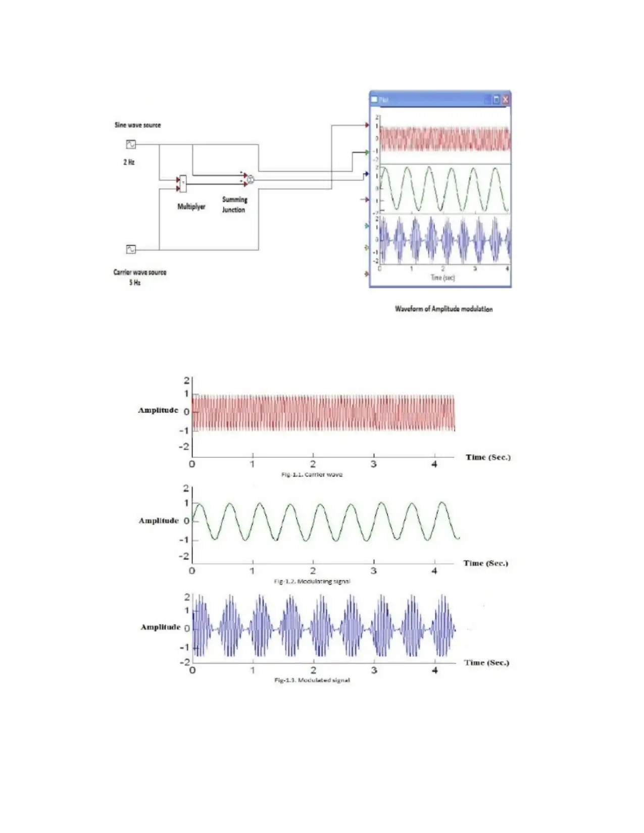
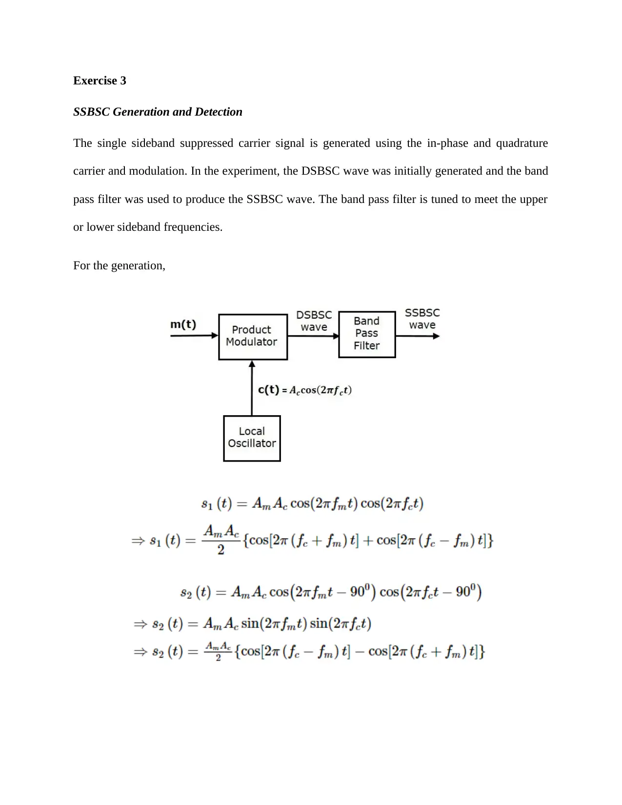
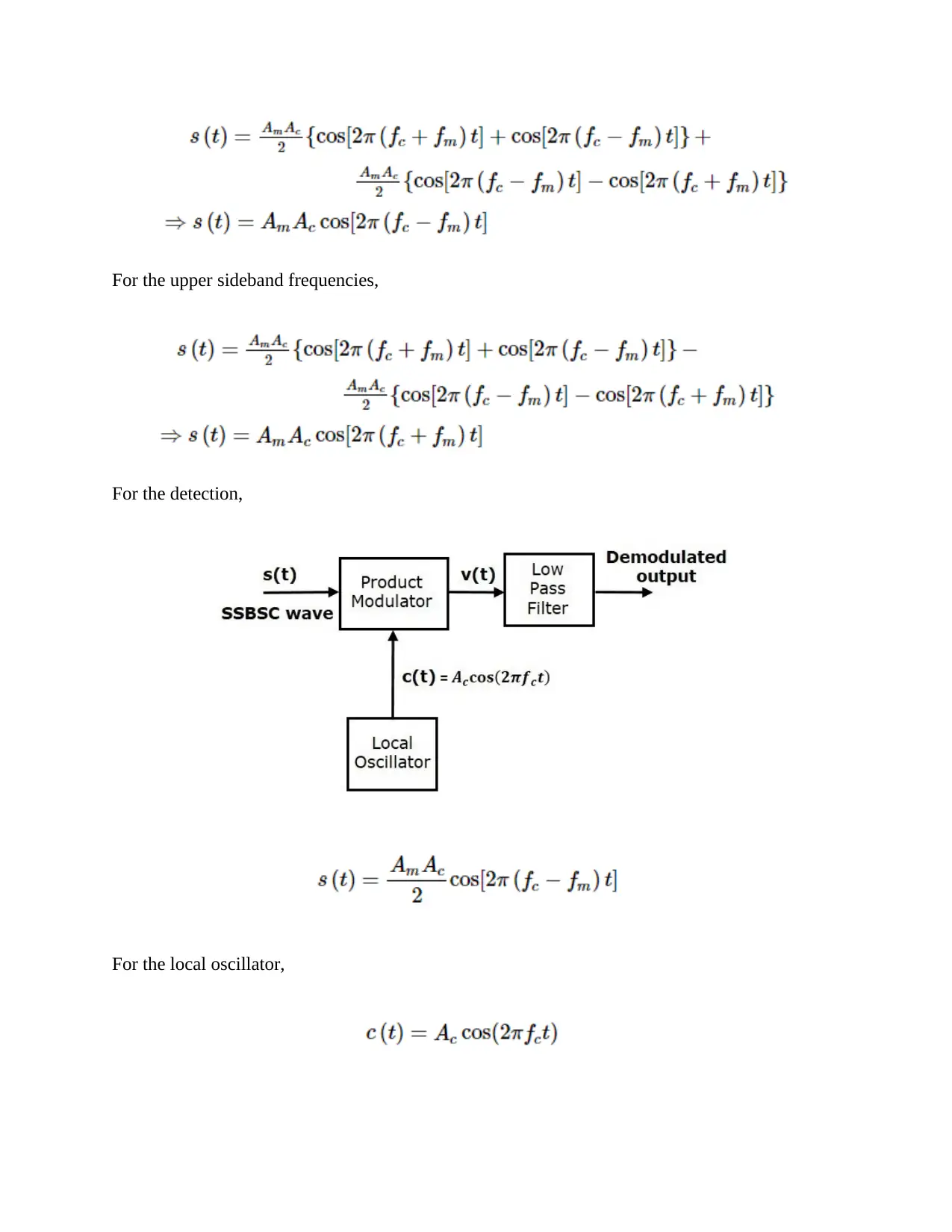
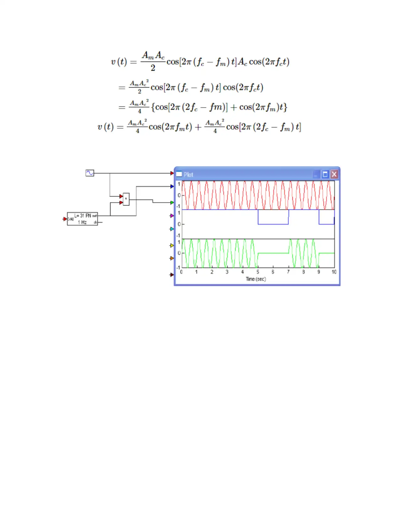
This assignment report details an experiment using CommSim, a communication system simulation package, to explore various modulation schemes. The experiment covers the generation and detection of Amplitude Modulation (AM), Single Sideband Suppressed Carrier (SSBSC), and Frequency Modulation (FM) signals, as well as On-Off Keying (OOK) modulation. The report outlines the experimental procedures, including the use of sine wave generators, summing functions, spectrum analyzers, and filters. The results section presents the findings for each modulation technique, including formulas and graphical representations. The discussion section compares the advantages and disadvantages of AM and FM. The conclusion summarizes the key concepts of a communication system and the role of modulation in transmitting digital data over analog carriers. The bibliography lists the references used in the experiment.
1 out of 15


Your All-in-One AI-Powered Toolkit for Academic Success.
+13062052269
info@desklib.com
Available 24*7 on WhatsApp / Email
![[object Object]](/_next/static/media/star-bottom.7253800d.svg)
Copyright © 2020–2026 A2Z Services. All Rights Reserved. Developed and managed by ZUCOL.