Analysis of Racing Car Wing Aerodynamics Using Two Effective Computational Methods
VerifiedAdded on 2023/06/11
|15
|4195
|68
AI Summary
This project is about analyzing aerodynamics of a racing car wing using two main computational methods: computational fluid dynamics (CFD) simulation and wind tunnel test. The main aim of the project is to examine how aerodynamics affect the performance of racing cars. CFD simulation is based on theoretical calculations of aerodynamics while wind tunnel is based on experimental analysis of aerodynamics that presents real conditions. Therefore wind tunnel test provides more realistic results on the performance of racing car. For this reason, results obtained from CFD simulation have to be verified with the wind tunnel test results.
Contribute Materials
Your contribution can guide someone’s learning journey. Share your
documents today.
Project Proposal 1
Analysis of Racing Car Wing Aerodynamics Using Two Effective Computational Methods
Name
Course
Professor
University
City/state
Date
Analysis of Racing Car Wing Aerodynamics Using Two Effective Computational Methods
Name
Course
Professor
University
City/state
Date
Secure Best Marks with AI Grader
Need help grading? Try our AI Grader for instant feedback on your assignments.
Project Proposal 2
Executive Summary
This project is about analyzing aerodynamics of a racing car wing using two main computational
methods: computational fluid dynamics (CFD) simulation and wind tunnel test. The main aim of
the project is to examine how aerodynamics affect the performance of racing cars. CFD
simulation is based on theoretical calculations of aerodynamics while wind tunnel is based on
experimental analysis of aerodynamics that presents real conditions. Therefore wind tunnel test
provides more realistic results on the performance of racing car. For this reason, results obtained
from CFD simulation have to be verified with the wind tunnel test results. In this project, a
racing car wing’s aerodynamic model will be established and analyzed. The difference between
results obtained from CFD simulation and wind tunnel test is expected to be small. In both tests,
six components (namely drag force, side force, lift force, rolling moment, yawing moment and
pitching moments) and torques of the aerodynamic model will be measured.
Project Proposal 3
Table of Contents
Executive Summary...................................................................................................................................2
1. Introduction.......................................................................................................................................4
2. Literature Review..............................................................................................................................5
3. Research Question, Aims/Objectives and Sub-goals.......................................................................8
4. Theoretical Content...........................................................................................................................8
5. Experimental Set-up..........................................................................................................................9
5.1. Wind tunnel testing....................................................................................................................9
5.2. CFD simulation........................................................................................................................10
6. Results, Outcome and Relevance....................................................................................................11
7. Project Planning..............................................................................................................................12
8. Conclusions......................................................................................................................................13
References................................................................................................................................................14
Project Proposal 4
1. Introduction
Aerodynamics is a very important element in the performance of racing cars. The speed
and efficiency of these cars are largely influenced by how air flows around their bodies
(Diasinos, et al., 2014). This drives designers of the cars to ensure that air flow round the cars’
wings provide minimal air drag force and reasonable downward pressure. A racing car’s wing
comprises of three main parts: top/front wings, bottom/rear wings and wings on both sides of the
car. These components have a direct impact on the car’s aerodynamic downforce. Downforce
refers to the downward thrust that is created by the car’s aerodynamic characteristics. The front
wings are more aerodynamically efficient than the other parts because they affect how air flows
at the other components (TotalSim Ltd, 2016). These wings create downforce that is responsible
for enhancing grip of the car’s front tires, and also optimizes air flow to the other parts of the car
(Formula One World Championship Limited, 2017). The wings on both sides of the car are
responsible for guiding flow of air front the front to the rear side. The rear wings are less
aerodynamically efficient because air flow at them is affected by other components of the car
such as front wheels, front wings, mirrors, exhaust, driver’s helmet, etc. Nevertheless, the rear
wings are expected to produce more than double the downforce produced by the front wings for
the driver to handle and balance the car efficiently. To achieve this, the aspect ratio of the rear
wing is larger. These wings also have additional elements that help in increasing downforce.
Both front and rear wings are mainly used in acceleration, cornering and braking forces (Rapid-
Racer.com, 2016).
This project will examine the aerodynamics of the entire wing, which has to be designed
such that it reduces drag and increases downforce (reduce lift and increase grip) so that the car
can move at its design speed, even when negotiating a corner, without being lifted off the track.
Secure Best Marks with AI Grader
Need help grading? Try our AI Grader for instant feedback on your assignments.
Project Proposal 5
Findings from the project can be used to optimize the design of racing car’s wings, especially
their shape (cross-section, surface area and aspect ratio) and orientation (angle of attack). This
will be of great importance in the manufacturing industry of racing cars as it will help to increase
speed, safety, performance and fuel efficiency of racing cars. Other sections of this report
include: literature review; research question, aims/objectives and sub-goals; theoretical content;
experimental set-up; results, outcome and relevance; project planning; and conclusions.
2. Literature Review
Performance of racing cars depends on a wide range of factors, including the engine, road,
suspension, tires, driver and aerodynamics. In the recent years, aerodynamics (i.e. movement of
air around racing cars) has become very critical in race car design because it helps designers
utilize the principle of downforce (negative lift) (Katz, 2006). Race car wings operate on the
same principle as wings of aircrafts, but in the reverse. The race cars have two sides of the wing,
and the speed of air on each side is different, creating a pressure difference that is called
Bernoulli’s principle. The balancing of this pressure causes the wing to move towards the low
pressure zone. Therefore the race car wings are designed to create adequate negative lift
(aerodynamic downforce) so as to attain optimum balance.
Several decades ago, race cars were designed with high mountings and movable wings to
generate aerodynamic downforce. But regulations were introduced in 1970 to limit the location
and size of wings so as to reduce the number of accidents. The concept of designing wings that
increase downforce started in mid 1970s and has been improving ever since. Today, the freedom
of aerodynamicists is very limited in relation to the width, height and location of wings on race
cars (Axerio-Cilies, et al., 2012). Front and rear wings are the most typical aerodynamic devices
on racing cars. These devices account for about 60% of the total downforce generated by a race
Project Proposal 6
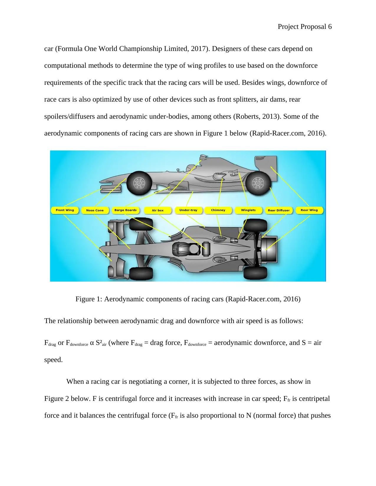
car (Formula One World Championship Limited, 2017). Designers of these cars depend on
computational methods to determine the type of wing profiles to use based on the downforce
requirements of the specific track that the racing cars will be used. Besides wings, downforce of
race cars is also optimized by use of other devices such as front splitters, air dams, rear
spoilers/diffusers and aerodynamic under-bodies, among others (Roberts, 2013). Some of the
aerodynamic components of racing cars are shown in Figure 1 below (Rapid-Racer.com, 2016).
Figure 1: Aerodynamic components of racing cars (Rapid-Racer.com, 2016)
The relationship between aerodynamic drag and downforce with air speed is as follows:
Fdrag or Fdownforce α S²air (where Fdrag = drag force, Fdownforce = aerodynamic downforce, and S = air
speed.
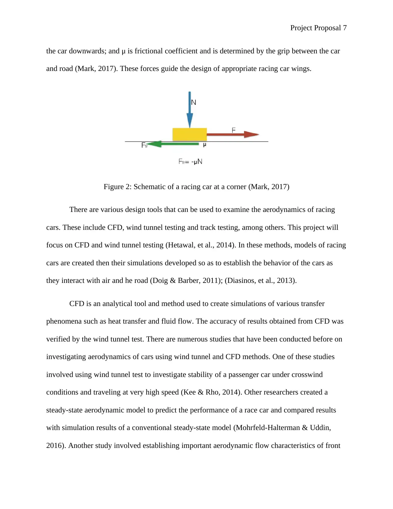
When a racing car is negotiating a corner, it is subjected to three forces, as show in
Figure 2 below. F is centrifugal force and it increases with increase in car speed; Ffr is centripetal
force and it balances the centrifugal force (Ffr is also proportional to N (normal force) that pushes
car (Formula One World Championship Limited, 2017). Designers of these cars depend on
computational methods to determine the type of wing profiles to use based on the downforce
requirements of the specific track that the racing cars will be used. Besides wings, downforce of
race cars is also optimized by use of other devices such as front splitters, air dams, rear
spoilers/diffusers and aerodynamic under-bodies, among others (Roberts, 2013). Some of the
aerodynamic components of racing cars are shown in Figure 1 below (Rapid-Racer.com, 2016).
Figure 1: Aerodynamic components of racing cars (Rapid-Racer.com, 2016)
The relationship between aerodynamic drag and downforce with air speed is as follows:
Fdrag or Fdownforce α S²air (where Fdrag = drag force, Fdownforce = aerodynamic downforce, and S = air
speed.
When a racing car is negotiating a corner, it is subjected to three forces, as show in
Figure 2 below. F is centrifugal force and it increases with increase in car speed; Ffr is centripetal
force and it balances the centrifugal force (Ffr is also proportional to N (normal force) that pushes
Project Proposal 7
the car downwards; and μ is frictional coefficient and is determined by the grip between the car
and road (Mark, 2017). These forces guide the design of appropriate racing car wings.
Figure 2: Schematic of a racing car at a corner (Mark, 2017)
There are various design tools that can be used to examine the aerodynamics of racing
cars. These include CFD, wind tunnel testing and track testing, among others. This project will
focus on CFD and wind tunnel testing (Hetawal, et al., 2014). In these methods, models of racing
cars are created then their simulations developed so as to establish the behavior of the cars as
they interact with air and he road (Doig & Barber, 2011); (Diasinos, et al., 2013).
CFD is an analytical tool and method used to create simulations of various transfer
phenomena such as heat transfer and fluid flow. The accuracy of results obtained from CFD was
verified by the wind tunnel test. There are numerous studies that have been conducted before on
investigating aerodynamics of cars using wind tunnel and CFD methods. One of these studies
involved using wind tunnel test to investigate stability of a passenger car under crosswind
conditions and traveling at very high speed (Kee & Rho, 2014). Other researchers created a
steady-state aerodynamic model to predict the performance of a race car and compared results
with simulation results of a conventional steady-state model (Mohrfeld-Halterman & Uddin,
2016). Another study involved establishing important aerodynamic flow characteristics of front
Paraphrase This Document
Need a fresh take? Get an instant paraphrase of this document with our AI Paraphraser
Project Proposal 8
wing of a racing car operating at an increasing yaw angle (Altinisik, et al., 2015). In a different
study, flow characteristics and aerodynamic loads of a rear wing were analyzed by developing a
computational model using CFD (Buljac & Dzijan, 2016). Another similar study involved use of
wind tunnel test to establish aerodynamic factors that affect formation of overtaking
opportunities in car racing competitions (Soso & Wilson, 2006). A wind tunnel test was also
performed in another study to investigate pressure distributions and drag forces at increasing yaw
angles of a racing car model. Last but not least, a combination of CFD and wind tunnel test was
used by a researcher to investigate aerodynamic drag so as to establish reasons for increasing
drag coefficients of passenger cars (Zhang, 2012).
These previous studies show that there is enough content with which the results obtained
from this project can be compared. Therefore this project will provide vital information on the
comparison between wind tunnel test and CFD simulation
3. Research Question, Aims/Objectives and Sub-goals
The main research question in this project is: what is the relationship between results
obtained from wind tunnel test and CFD simulation of a racing car wing? Based on this question,
the main objective of the project is to compare results obtained from CFD simulation and wind
tunnel test of a racing car wing. To achieve this objective, a wind tunnel test will be performed
on a racing car wing then a CFD simulation model of the same racing car wing will be created
using CFD software.
4. Theoretical Content
The hypothesis to be tested in this project is that the results obtained by analyzing a racing
car wing using wind tunnel test are similar to those from CFD simulation and provides useful
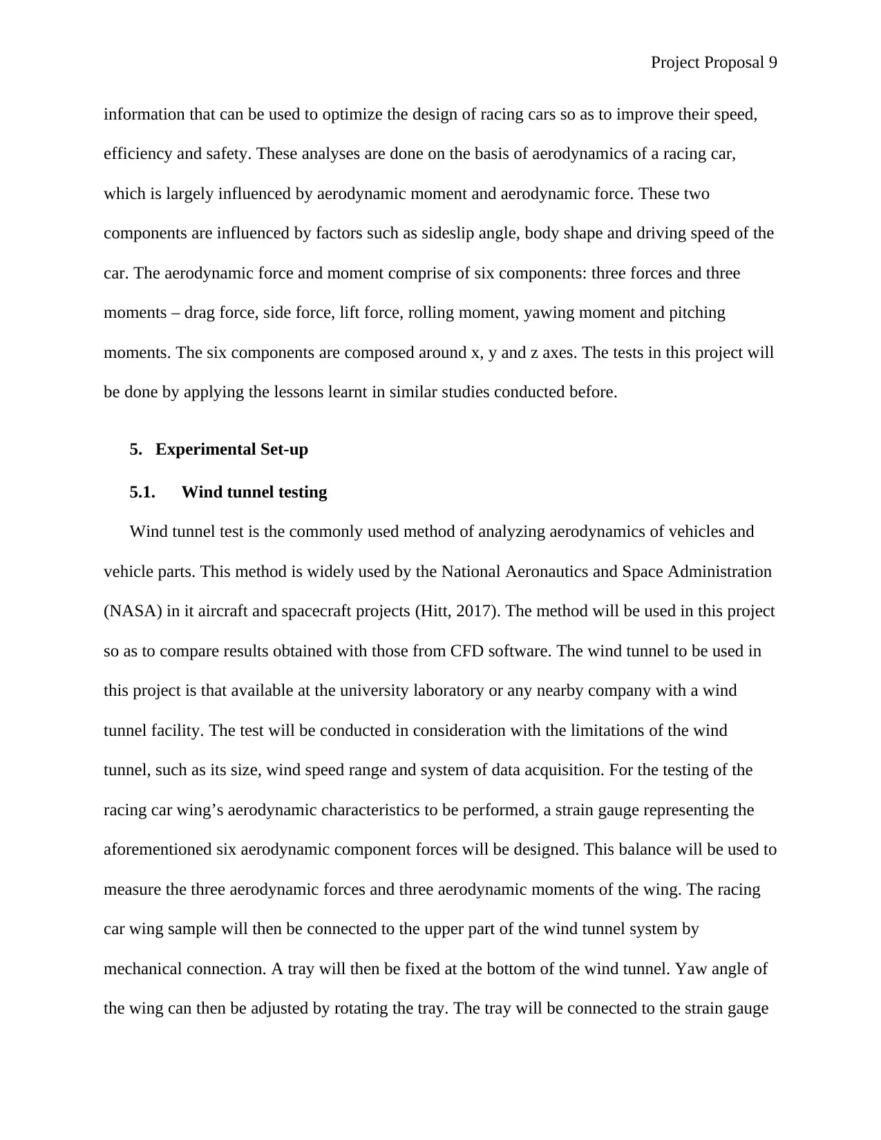
Project Proposal 9
information that can be used to optimize the design of racing cars so as to improve their speed,
efficiency and safety. These analyses are done on the basis of aerodynamics of a racing car,
which is largely influenced by aerodynamic moment and aerodynamic force. These two
components are influenced by factors such as sideslip angle, body shape and driving speed of the
car. The aerodynamic force and moment comprise of six components: three forces and three
moments – drag force, side force, lift force, rolling moment, yawing moment and pitching
moments. The six components are composed around x, y and z axes. The tests in this project will
be done by applying the lessons learnt in similar studies conducted before.
5. Experimental Set-up
5.1. Wind tunnel testing
Wind tunnel test is the commonly used method of analyzing aerodynamics of vehicles and
vehicle parts. This method is widely used by the National Aeronautics and Space Administration
(NASA) in it aircraft and spacecraft projects (Hitt, 2017). The method will be used in this project
so as to compare results obtained with those from CFD software. The wind tunnel to be used in
this project is that available at the university laboratory or any nearby company with a wind
tunnel facility. The test will be conducted in consideration with the limitations of the wind
tunnel, such as its size, wind speed range and system of data acquisition. For the testing of the
racing car wing’s aerodynamic characteristics to be performed, a strain gauge representing the
aforementioned six aerodynamic component forces will be designed. This balance will be used to
measure the three aerodynamic forces and three aerodynamic moments of the wing. The racing
car wing sample will then be connected to the upper part of the wind tunnel system by
mechanical connection. A tray will then be fixed at the bottom of the wind tunnel. Yaw angle of
the wing can then be adjusted by rotating the tray. The tray will be connected to the strain gauge
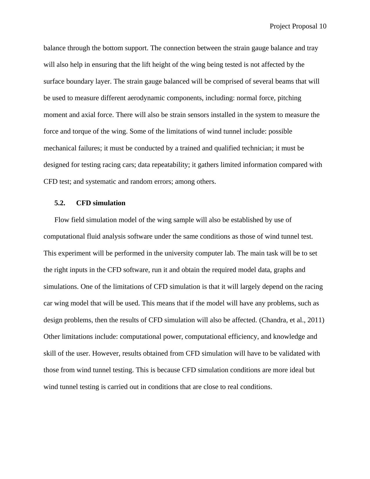
Project Proposal 10
balance through the bottom support. The connection between the strain gauge balance and tray
will also help in ensuring that the lift height of the wing being tested is not affected by the
surface boundary layer. The strain gauge balanced will be comprised of several beams that will
be used to measure different aerodynamic components, including: normal force, pitching
moment and axial force. There will also be strain sensors installed in the system to measure the
force and torque of the wing. Some of the limitations of wind tunnel include: possible
mechanical failures; it must be conducted by a trained and qualified technician; it must be
designed for testing racing cars; data repeatability; it gathers limited information compared with
CFD test; and systematic and random errors; among others.
5.2. CFD simulation
Flow field simulation model of the wing sample will also be established by use of
computational fluid analysis software under the same conditions as those of wind tunnel test.
This experiment will be performed in the university computer lab. The main task will be to set
the right inputs in the CFD software, run it and obtain the required model data, graphs and
simulations. One of the limitations of CFD simulation is that it will largely depend on the racing
car wing model that will be used. This means that if the model will have any problems, such as
design problems, then the results of CFD simulation will also be affected. (Chandra, et al., 2011)
Other limitations include: computational power, computational efficiency, and knowledge and
skill of the user. However, results obtained from CFD simulation will have to be validated with
those from wind tunnel testing. This is because CFD simulation conditions are more ideal but
wind tunnel testing is carried out in conditions that are close to real conditions.
Secure Best Marks with AI Grader
Need help grading? Try our AI Grader for instant feedback on your assignments.
Project Proposal 11
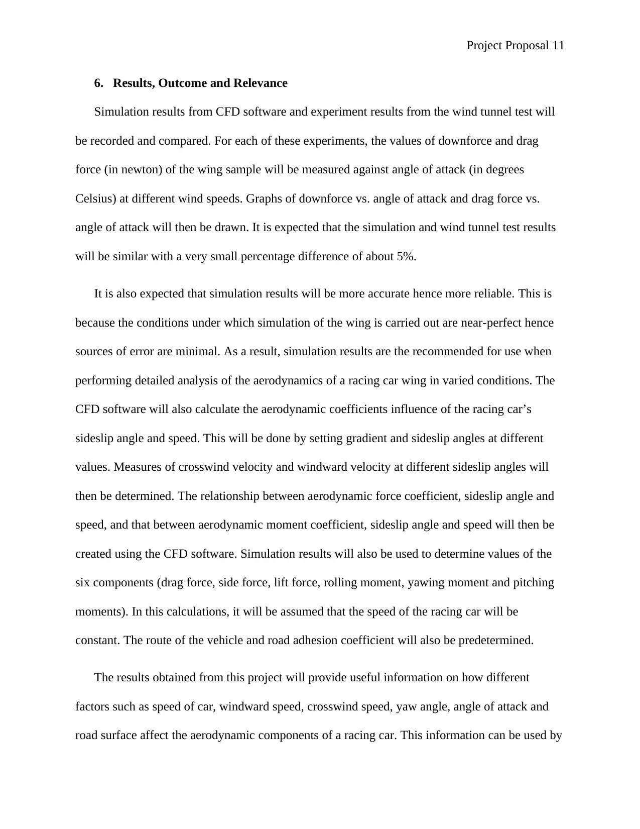
6. Results, Outcome and Relevance
Simulation results from CFD software and experiment results from the wind tunnel test will
be recorded and compared. For each of these experiments, the values of downforce and drag
force (in newton) of the wing sample will be measured against angle of attack (in degrees
Celsius) at different wind speeds. Graphs of downforce vs. angle of attack and drag force vs.
angle of attack will then be drawn. It is expected that the simulation and wind tunnel test results
will be similar with a very small percentage difference of about 5%.
It is also expected that simulation results will be more accurate hence more reliable. This is
because the conditions under which simulation of the wing is carried out are near-perfect hence
sources of error are minimal. As a result, simulation results are the recommended for use when
performing detailed analysis of the aerodynamics of a racing car wing in varied conditions. The
CFD software will also calculate the aerodynamic coefficients influence of the racing car’s
sideslip angle and speed. This will be done by setting gradient and sideslip angles at different
values. Measures of crosswind velocity and windward velocity at different sideslip angles will
then be determined. The relationship between aerodynamic force coefficient, sideslip angle and
speed, and that between aerodynamic moment coefficient, sideslip angle and speed will then be
created using the CFD software. Simulation results will also be used to determine values of the
six components (drag force, side force, lift force, rolling moment, yawing moment and pitching
moments). In this calculations, it will be assumed that the speed of the racing car will be
constant. The route of the vehicle and road adhesion coefficient will also be predetermined.
The results obtained from this project will provide useful information on how different
factors such as speed of car, windward speed, crosswind speed, yaw angle, angle of attack and
road surface affect the aerodynamic components of a racing car. This information can be used by
Project Proposal 12
engineers and designers to design wings that optimize the performance of racing cars by
reducing drag force and increasing downforce.
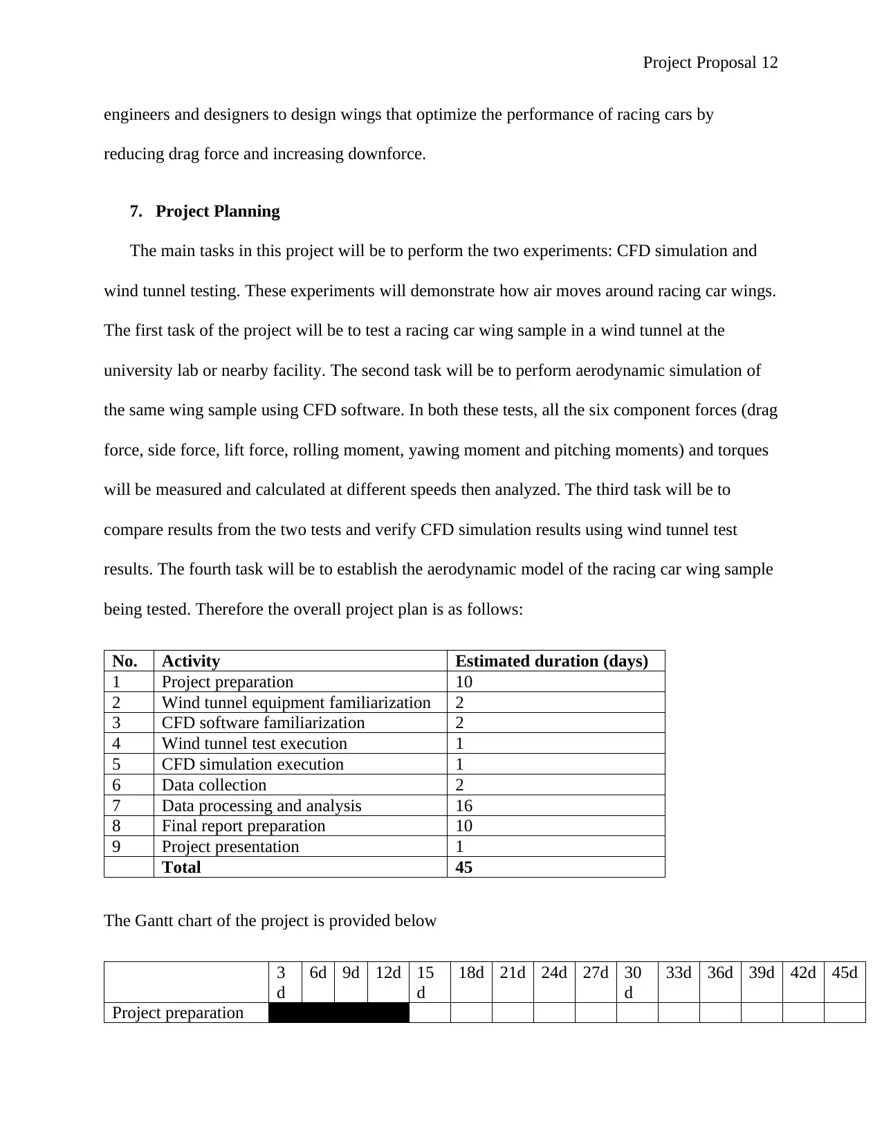
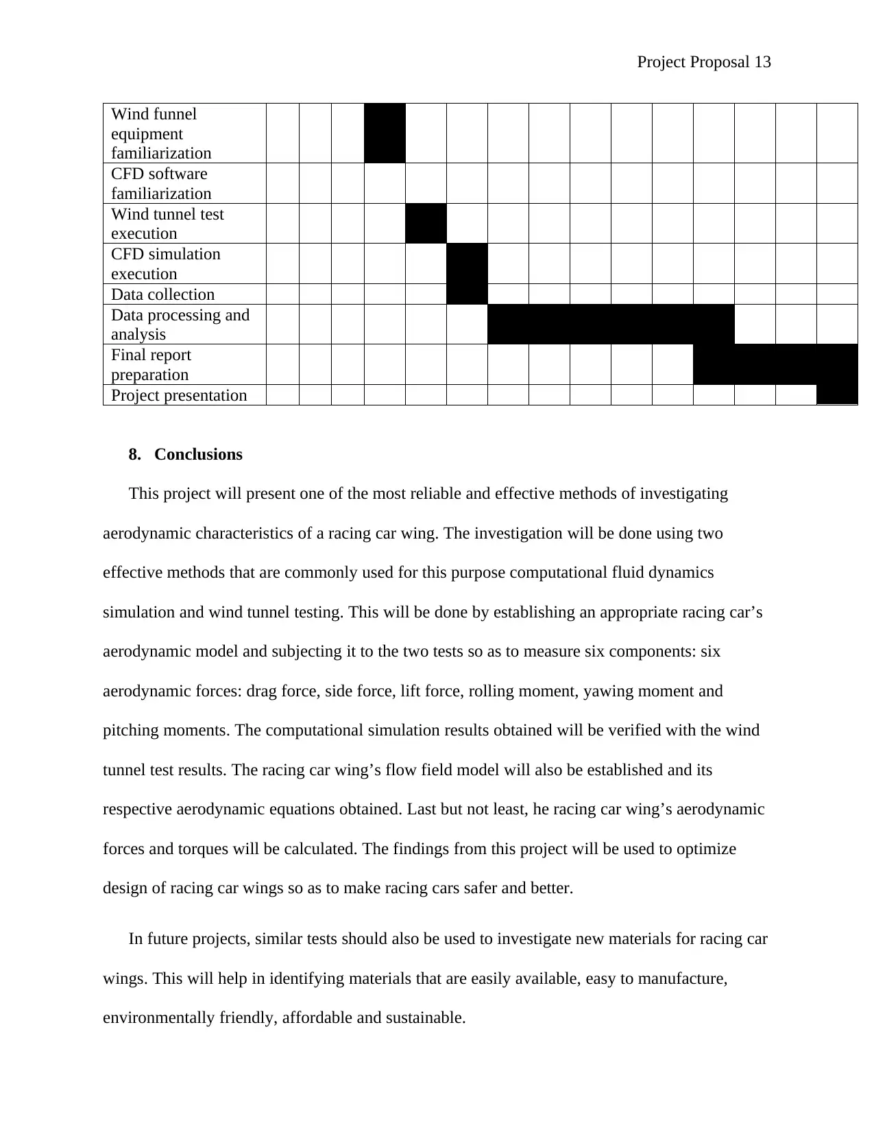
7. Project Planning
The main tasks in this project will be to perform the two experiments: CFD simulation and
wind tunnel testing. These experiments will demonstrate how air moves around racing car wings.
The first task of the project will be to test a racing car wing sample in a wind tunnel at the
university lab or nearby facility. The second task will be to perform aerodynamic simulation of
the same wing sample using CFD software. In both these tests, all the six component forces (drag
force, side force, lift force, rolling moment, yawing moment and pitching moments) and torques
will be measured and calculated at different speeds then analyzed. The third task will be to
compare results from the two tests and verify CFD simulation results using wind tunnel test
results. The fourth task will be to establish the aerodynamic model of the racing car wing sample
being tested. Therefore the overall project plan is as follows:
No. Activity Estimated duration (days)
1 Project preparation 10
2 Wind tunnel equipment familiarization 2
3 CFD software familiarization 2
4 Wind tunnel test execution 1
5 CFD simulation execution 1
6 Data collection 2
7 Data processing and analysis 16
8 Final report preparation 10
9 Project presentation 1
Total 45
The Gantt chart of the project is provided below
3
d
6d 9d 12d 15
d
18d 21d 24d 27d 30
d
33d 36d 39d 42d 45d
Project preparation
engineers and designers to design wings that optimize the performance of racing cars by
reducing drag force and increasing downforce.
7. Project Planning
The main tasks in this project will be to perform the two experiments: CFD simulation and
wind tunnel testing. These experiments will demonstrate how air moves around racing car wings.
The first task of the project will be to test a racing car wing sample in a wind tunnel at the
university lab or nearby facility. The second task will be to perform aerodynamic simulation of
the same wing sample using CFD software. In both these tests, all the six component forces (drag
force, side force, lift force, rolling moment, yawing moment and pitching moments) and torques
will be measured and calculated at different speeds then analyzed. The third task will be to
compare results from the two tests and verify CFD simulation results using wind tunnel test
results. The fourth task will be to establish the aerodynamic model of the racing car wing sample
being tested. Therefore the overall project plan is as follows:
No. Activity Estimated duration (days)
1 Project preparation 10
2 Wind tunnel equipment familiarization 2
3 CFD software familiarization 2
4 Wind tunnel test execution 1
5 CFD simulation execution 1
6 Data collection 2
7 Data processing and analysis 16
8 Final report preparation 10
9 Project presentation 1
Total 45
The Gantt chart of the project is provided below
3
d
6d 9d 12d 15
d
18d 21d 24d 27d 30
d
33d 36d 39d 42d 45d
Project preparation
Project Proposal 13
Wind funnel
equipment
familiarization
CFD software
familiarization
Wind tunnel test
execution
CFD simulation
execution
Data collection
Data processing and
analysis
Final report
preparation
Project presentation
8. Conclusions
This project will present one of the most reliable and effective methods of investigating
aerodynamic characteristics of a racing car wing. The investigation will be done using two
effective methods that are commonly used for this purpose computational fluid dynamics
simulation and wind tunnel testing. This will be done by establishing an appropriate racing car’s
aerodynamic model and subjecting it to the two tests so as to measure six components: six
aerodynamic forces: drag force, side force, lift force, rolling moment, yawing moment and
pitching moments. The computational simulation results obtained will be verified with the wind
tunnel test results. The racing car wing’s flow field model will also be established and its
respective aerodynamic equations obtained. Last but not least, he racing car wing’s aerodynamic
forces and torques will be calculated. The findings from this project will be used to optimize
design of racing car wings so as to make racing cars safer and better.
In future projects, similar tests should also be used to investigate new materials for racing car
wings. This will help in identifying materials that are easily available, easy to manufacture,
environmentally friendly, affordable and sustainable.
Paraphrase This Document
Need a fresh take? Get an instant paraphrase of this document with our AI Paraphraser
Project Proposal 14
References
Altinisik, A., Yemenici, O. & Umur, H., 2015. Aerodynamic Analysis of a Passenger Car at Yaw Angle and
Two-Vehicle Platoon. Journal of Fluids Engineering-Transactions of the ASME, 137(12).
Axerio-Cilies, J., Issakhanian, E., Jimenez, J. & Iaccarino, G., 2012. An Aerodynamic Investigation of an
Isolated Stationary Formula 1 Wheel Assembly. Journal of Fluids Engineering, 134(2).
Buljac, A. & Dzijan, I., 2016. Automobile Aerodynamics Influenced by Airfoil-shaped Rear Wing.
International Journal of Automotive Technology, 17(3), pp. 377-385.
Chandra, S., Lee, A., Gorrell, S. & Jensen, C., 2011. CFD Analysis of PACE Formula-1 Car. Computer-Aided
Design & Applications, Volume 1, pp. 1-14.
Diasinos, S., Barber, T. & Doig, G., 2013. Influence of Wing Span on the Aerodynamics of Wings in
Ground Effect. Journal of Aerospace Engineering, 227(3), pp. 569-573.
Diasinos, S., Doig, G. & Barber, T., 2014. On the Interaction of a Racing Car Front Wing and Exposed
Wheel. Aeronautcal Journal, 118(1210), pp. 1385-1407.
Doig, G. & Barber, T., 2011. Coniderations for Numerical Modeling of Inverted Wings in Ground Effect.
AIAAJ, 49(10), pp. 2330-2333.
Formula One World Championship Limited, 2017. Aerodynamics. [Online]
Available at: https://www.formula1.com/en/championship/inside-f1/understanding-f1-racing/
Aerodynamics.html
[Accessed 5 June 2018].
Hetawal, S., Gophane, M., Ajay, B. & Mukkamala, Y., 2014. Aerodynamic Study of Formula SAE Car.
Procedia Engineering, Volume 97, pp. 1198-1207.
Hitt, D., 2017. What Are Wind Tunnels?. [Online]
Available at: https://www.nasa.gov/audience/forstudents/k-4/stories/nasa-knows/what-are-wind-
tunnels-k4.html
[Accessed 6 June 2018].
Katz, J., 2006. Aerodynamics of Race Cars. Annual Review of Fluid Mechanics, 38(1), pp. 27-63.
Kee, J. & Rho, J., 2014. High Speed Driving Stability of Passenger Car Under Crosswind Effects.
International Journal of Automotive Technology, 15(5), pp. 741-747.
Mark, T., 2017. How Elemental Cars Improved Its Cornering Speeds for the RP1. [Online]
Available at: http://www.lcs-fast.com/elemental/#
Project Proposal 15
[Accessed 5 June 2018].
Mohrfeld-Halterman, J. & Uddin, M., 2016. High Fidelity Quasi Steady-State Aerodynamic Model Effects
on Race Vehicle Performance Predictions Using Multi-body Simulation. Vehicle System Dynamics, 54(7),
pp. 963-981.
Rapid-Racer.com, 2016. Aerodynamic Upgrades. [Online]
Available at: http://www.rapid-racer.com/aerodynamic-upgrades.php
[Accessed 5 June 2018].
Roberts, N., 2013. Air Dams, Splitters, Spoilers and Wings – Downforce increases grip, grip decreases lap
times, and isn’t that the whole point?. [Online]
Available at: https://nasaspeed.news/tech/aero/air-dams-splitters-spoilers-and-wings-downforce-
increases-grip-grip-decreases-lap-times-and-isnt-that-the-whole-point/
[Accessed 5 June 2018].
Soso, M. & Wilson, P., 2006. Aerodynamics of a Wing in Ground Effect in Generic Racing Car Wake
Flows. Journal of Automobile Engineering, 220(D1), pp. 1-13.
TotalSim Ltd, 2016. Secrets of Formula 1 Part 3 - The Role of the Front Wing. [Online]
Available at: https://www.totalsimulation.co.uk/secrets-formula-1-part-3-role-front-wing/
[Accessed 6 June 2018].
Zhang, Y. Z. J., 2012. Wind Tunnel Tests and Aerodynamic Numerical Simulatios of Car Opening
Windows. Nonlinear Dynamics, 58(1), pp. 62-78.
[Accessed 5 June 2018].
Mohrfeld-Halterman, J. & Uddin, M., 2016. High Fidelity Quasi Steady-State Aerodynamic Model Effects
on Race Vehicle Performance Predictions Using Multi-body Simulation. Vehicle System Dynamics, 54(7),
pp. 963-981.
Rapid-Racer.com, 2016. Aerodynamic Upgrades. [Online]
Available at: http://www.rapid-racer.com/aerodynamic-upgrades.php
[Accessed 5 June 2018].
Roberts, N., 2013. Air Dams, Splitters, Spoilers and Wings – Downforce increases grip, grip decreases lap
times, and isn’t that the whole point?. [Online]
Available at: https://nasaspeed.news/tech/aero/air-dams-splitters-spoilers-and-wings-downforce-
increases-grip-grip-decreases-lap-times-and-isnt-that-the-whole-point/
[Accessed 5 June 2018].
Soso, M. & Wilson, P., 2006. Aerodynamics of a Wing in Ground Effect in Generic Racing Car Wake
Flows. Journal of Automobile Engineering, 220(D1), pp. 1-13.
TotalSim Ltd, 2016. Secrets of Formula 1 Part 3 - The Role of the Front Wing. [Online]
Available at: https://www.totalsimulation.co.uk/secrets-formula-1-part-3-role-front-wing/
[Accessed 6 June 2018].
Zhang, Y. Z. J., 2012. Wind Tunnel Tests and Aerodynamic Numerical Simulatios of Car Opening
Windows. Nonlinear Dynamics, 58(1), pp. 62-78.
1 out of 15
Related Documents


Your All-in-One AI-Powered Toolkit for Academic Success.
+13062052269
info@desklib.com
Available 24*7 on WhatsApp / Email
![[object Object]](/_next/static/media/star-bottom.7253800d.svg)
Unlock your academic potential
© 2024 | Zucol Services PVT LTD | All rights reserved.