RANS Simulation of Laboratory Scale Premixed V-Flame
Added on 2023-04-22
27 Pages5341 Words324 Views
RANS simulation of a laboratory scale premixed V- flame
1
REYNOLDS – AVERAGEED NAVIER STOKES (RANS) SIMULATION OF
ROD – STABILIZED PREMIXED TURBULENT FLAME
1
REYNOLDS – AVERAGEED NAVIER STOKES (RANS) SIMULATION OF
ROD – STABILIZED PREMIXED TURBULENT FLAME

RANS simulation of a laboratory scale premixed V- flame
2
DECLARATION
No portion of the work referred to in this thesis has been submitted in support
of an application for another degree or qualification of this or any other
university or other institute of learning.
2
DECLARATION
No portion of the work referred to in this thesis has been submitted in support
of an application for another degree or qualification of this or any other
university or other institute of learning.

RANS simulation of a laboratory scale premixed V- flame
3
ABSTRACT
The laboratory-scale turbulent rod stabilised premixed V-flame of Bell et al [9]
has been investigated. In the V-flame configuration, a stationary, non-planar
flame is produced which is oblique to the mean flow, and subject to mean shear,
strong tangential convection by the mean flow and flow divergence [58]. This
type of configuration is characterised by a continuously developing flame in a
statistically two-dimensional mean flow field; the turbulence intensity along the
leading edge of the flame brush decreases significantly while the individual flame
elements are connected in the stream wise direction [58]. The experimental
results are used here as a benchmark to compare the RANS calculations. A
similar type of configuration has been studied by Kolla et al [85, 89] and Robin
et al [132, 133] using different RANS modelling approaches; the principal
novelty of this study lies in the comparison of several scalar dissipation models
in context of the BML approach.
RANS simulation of a laboratory scale premixed V- flame
4
INTRODUCTION
Combustion is a means of converting primary (chemical) energy into
secondary (heat) energy. It is one of the most important sources of
generating mechanical energy [10]. Most of the mechanical power
obtained from combustion is used for the generation of electricity, for
transport and also for industrial processes which include materials
processing, casting iron and steel [10]. Coal, oil and natural gas are the
main fossil fuel resources and are limited in supply. Fuel rich combustion
devices used in the past led to incomplete combustion of fuels, thus
leading to high levels of fuel consumption, pollutant formation and
greenhouse gas emissions. In the last two decades, the main concerns
arising from fossil fuel burning were nitrous oxide and sulphur oxide
emission, which led to ozone layer depletion, smog and acid rain.
However, now it is widely accepted that greenhouse emissions are one of
the key factors adversely affecting the environment and causing global
warming. According to recent reports by the Intergovernmental Panel on
Climate Change [74] and the International Energy Agency [75],
combustion of fossil fuels in the industrial, energy, transport and domestic
sectors contribute approximately 71% of the total greenhouse gas
emissions. It has been agreed by many countries under the United
Nations Framework Convention on Climate Change that more research
and development is required to reduce greenhouse gas emissions, and
that ongoing investment in cleaner energy sources is required [84]. While
renewable energy sources such as solar, wind and tidal energy provide an
alternative for energy production, combustion of fossil or alternative fuels
(such as bio-fuels or hydrogen) will remain the main source of energy for
the foreseeable future [73, 117]. Lean premixed combustion is one of the
avenues available to reduce greenhouse gas emissions and increase fuel
efficiency. In lean premixed combustion a homogeneous mixture of fuel
RANS simulation of a laboratory scale premixed V- flame
5
and excess oxidiser is used, thus significantly reducing the pollutant
emissions while improving the fuel efficiency of the combustion device
[51]. The use of lean premixed combustion in combustion devices is at an
early stage; recently lean premixed combustion has been adopted for
stationary land based gas turbine engines in the energy sector [78]. The
adoption of lean premixed combustion for aircraft engines is more difficult
due to the use of liquid fuels, as these fuels have to be vaporised and can
lead to problems like autoignition or flashback [51]. Although due to the
recent advances in technology, it is anticipated that aircraft engines are
likely to switch to lean premixed combustion [52, 77, 106, 136]. In the
automotive sector, the current generation of reciprocating engines such
as spark ignition [169] and compression ignition engines [165] burn
inhomogeneous mixtures that are lean over all. In such scenarios, the
premixed combustion mode still plays an important role in determining
the flame characteristics [162]. This implies that a fundamental
understanding of premixed turbulent combustion is required. Although
lean premixed combustion is appealing from the economic and
environmental point of view, it is very susceptible to instabilities due to
changes in fuel composition and weak reaction fronts in highly dynamic
fluid flows [142]. These instabilities can lead to excessive strains on the
engine and can significantly reduce lifetime of the engine. Hence more
accurate mathematical models are required to predict correct flame
behaviour in the engine development phase. The development of models
for turbulent premixed combustion applicable to a wide range of
combustion conditions is an area of intensive research by the combustion
community [16, 19, 117, 161]. Significant progress has been made in
modelling premixed turbulent combustion; however, a lot still remains to
be done. A few examples include accurate prediction of flame noise,
pollutant emission, flame turbulence interaction, prediction of flame
instability limits etc.
RANS simulation of a laboratory scale premixed V- flame
6
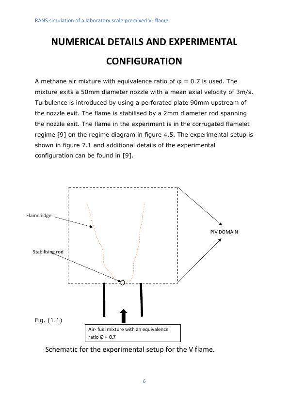
Stabilising rod
Flame edge
Air- fuel mixture with an equivalence
ratio Ø = 0.7
Schematic for the experimental setup for the V flame.
NUMERICAL DETAILS AND EXPERIMENTAL
CONFIGURATION
A methane air mixture with equivalence ratio of φ = 0.7 is used. The
mixture exits a 50mm diameter nozzle with a mean axial velocity of 3m/s.
Turbulence is introduced by using a perforated plate 90mm upstream of
the nozzle exit. The flame is stabilised by a 2mm diameter rod spanning
the nozzle exit. The flame in the experiment is in the corrugated flamelet
regime [9] on the regime diagram in figure 4.5. The experimental setup is
shown in figure 7.1 and additional details of the experimental
configuration can be found in [9].
Fig. (1.1)
PIV DOMAIN
6
Stabilising rod
Flame edge
Air- fuel mixture with an equivalence
ratio Ø = 0.7
Schematic for the experimental setup for the V flame.
NUMERICAL DETAILS AND EXPERIMENTAL
CONFIGURATION
A methane air mixture with equivalence ratio of φ = 0.7 is used. The
mixture exits a 50mm diameter nozzle with a mean axial velocity of 3m/s.
Turbulence is introduced by using a perforated plate 90mm upstream of
the nozzle exit. The flame is stabilised by a 2mm diameter rod spanning
the nozzle exit. The flame in the experiment is in the corrugated flamelet
regime [9] on the regime diagram in figure 4.5. The experimental setup is
shown in figure 7.1 and additional details of the experimental
configuration can be found in [9].
Fig. (1.1)
PIV DOMAIN
End of preview
Want to access all the pages? Upload your documents or become a member.