Redesigning a Vehicle for Improved Aerodynamics
Added on 2023-04-11
26 Pages4049 Words432 Views
Redesign a vehicle:
Abstract:
The world is increasingly becoming more sensitive in achieving a sustainable environment thus
causing a threat to the development and exploitation of oil and gas which leads to more pollution
on the atmosphere. This limitation has led to the increased fuel prices across the world because
the resource is getting depleted thus there is constant need of manufacturing more fuel efficient
vehicles that cause less hydrocarbon emission. This study will analyse the shape of Ford Mustang,
assess the aerodynamic optimisation techniques and implement a new design shape for the
vehicle. A Computation Fluid Domain (CFD) simulation was carried out to assess the flow of air
around the vehicle by determining the air characteristics and the strategies that need to be
implemented to improve the aerodynamics efficiency of the vehicle. This analysis will help
identify the best method that can be used to minimise the pressure difference between the pressure
stagnation at the front and the base drag at the rear of the vehicle. The fluid dynamic of the air
flow also have an effect on the vehicle body by causing the pressure difference between the lower
surface and the upper surface of the vehicle. The observable pressure difference caused an
induced lift on the vehicle. The optimisation of this ford model was caused by fluid dynamics
flowing on top of the vehicle and the process used resulted into a great improvement of the
aerodynamics abilities of the vehicle.
1.1. Computational Fluid dynamics (CFD):
CFD uses a numerical calculation method to analyse the fluid dynamics flowing around a body. The system

simulation involve very small finite volume elements subdivided from the main physical domain where certain
equation are solved numerically. There are three equations involved in fluid dynamics; that is momentum equation,
continuity and energy equations which are derived from the laws of physics which include the conservation of
energy, momentum, and energy. In CFD, the car simulation is only done on the external part of the car hence the
energy equation can be ignored to some extent because vehicles generally travel at low speed and at a constant
temperature, therefore, we can make an assumption that the flow is isothermal and incompressible (Levin and
Rigdal, 2011).
1.1.1. Navier-Stokes equations:
This is also referred to as the momentum equation that applies the Newton’s second law of fluid dynamics.
The equation is used to represent the conservation of momentum. The Navier- stokes equation is mainly
used to predict the fluid pressure and velocity in a given geometry (Levin and Rigdal, 2011)
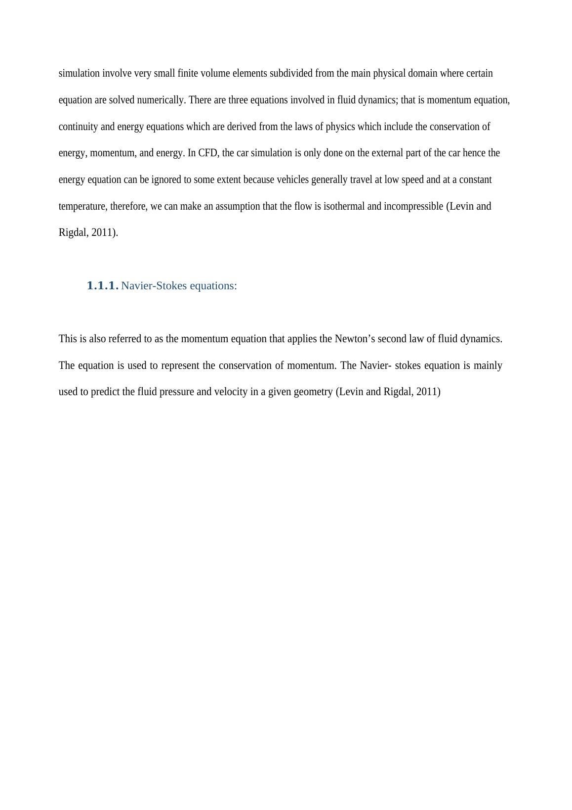
Figure 5: Navier-Stokes equations
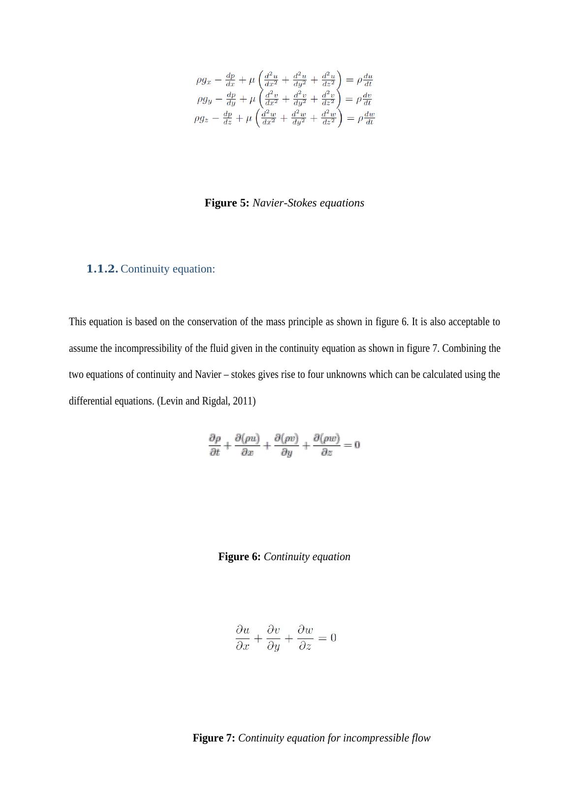
1.1.2. Continuity equation:
This equation is based on the conservation of the mass principle as shown in figure 6. It is also acceptable to
assume the incompressibility of the fluid given in the continuity equation as shown in figure 7. Combining the
two equations of continuity and Navier – stokes gives rise to four unknowns which can be calculated using the
differential equations. (Levin and Rigdal, 2011)
Figure 6: Continuity equation
Figure 7: Continuity equation for incompressible flow
1.1.3. Reynolds averaged Navier-Stokes (RANS):
The Navier-stokes equation can be broken down into RANS equations and solving these equations ease the
possibility of simulating the fluid flows. The process of breaking down the equation creates new terms such as
Reynolds stresses regarded as the function of velocity variations. The increased number of the unknown
equations relative to the number of equations result into a closure problem. To overcome this problem, a
model of turbulence is generated to produce solvable equations. The RANS equations need less calculation
requirements than the original equation (Levin and Rigdal, 2011).
1.1.4. Turbulence flow and modelling:
Turbulent flow is a stream comprising of different changes in pressure and velocity. Turbulent
flow is unpredictable and shifts through existence, these elements makes it difficult for CFD
reproductions to compute turbulent flow. With current PC limits the Navier-Stokes condition and
progression condition are unsolvable. By the utilization of turbulence models the stream field can
be determined with less registering force. These models will change the equation and considers
just the normal impacts of turbulence. A turbulence display cannot give a definite solutions,
instead it will give a gauge to the solution. The choice of turbulence would rely upon the capacity
of the PC and the dimension of accuracy required.
The k-epsilon (k-ε) is the most widely recognized turbulence model used to simulate turbulence
stream attributes in CFD simulation. The turbulence in the k-ε show is demonstrated by including
the turbulence viscosity (μt), making the k-ε display an Eddy Viscosity show. The k-ε is a semi-
experimental technique developed on how the active vitality is transported and the rate at which it
dissipates. The biggest eddies gets their active vitality from the main stream, this vitality is
transmitted into littler vortexes and after that winds up to internal energy. The k-ε show is a
RANS-model and it utilizes time normal terms, subsequently the model will pass up a great
opportunity contrasts in slope amid moment time steps. In the k-ε display the stream is ventured to
be totally turbulent, making the model powerful for just these conditions. (Levin and Rigdal,
2011)
2. Methodology:
2.1. Vehicle modelling:
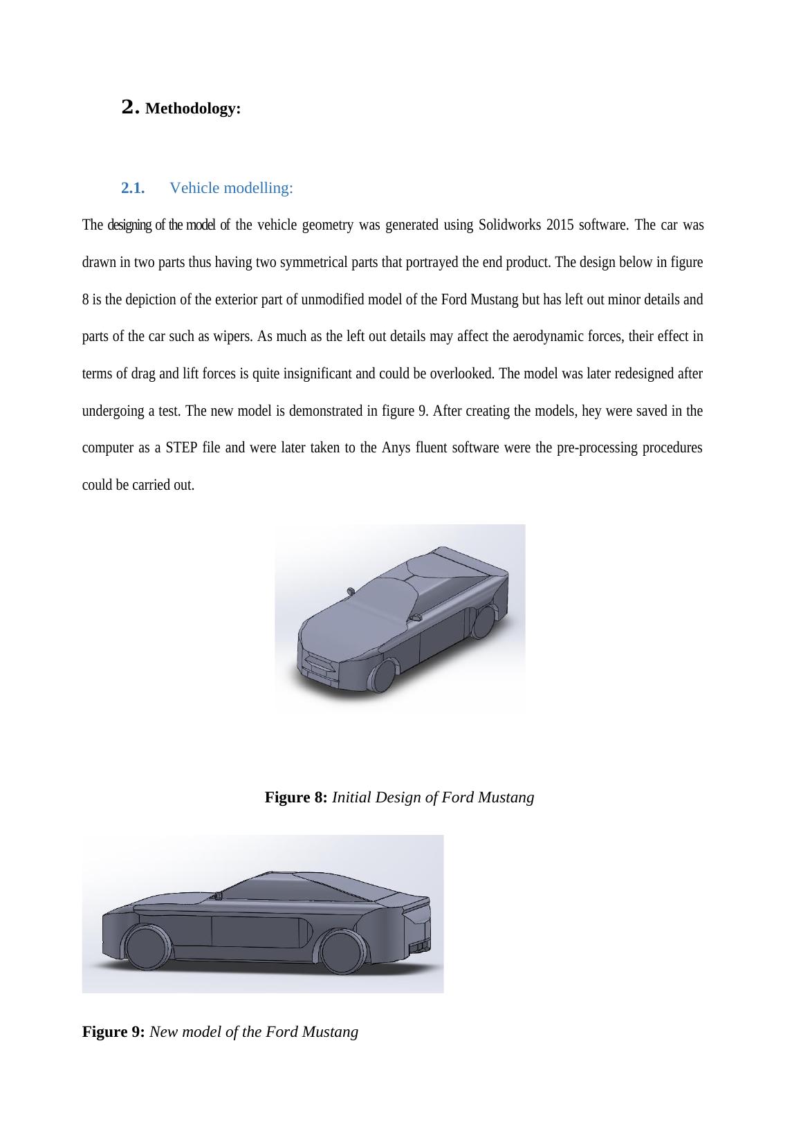
The designing of the model of the vehicle geometry was generated using Solidworks 2015 software. The car was
drawn in two parts thus having two symmetrical parts that portrayed the end product. The design below in figure
8 is the depiction of the exterior part of unmodified model of the Ford Mustang but has left out minor details and
parts of the car such as wipers. As much as the left out details may affect the aerodynamic forces, their effect in
terms of drag and lift forces is quite insignificant and could be overlooked. The model was later redesigned after
undergoing a test. The new model is demonstrated in figure 9. After creating the models, hey were saved in the
computer as a STEP file and were later taken to the Anys fluent software were the pre-processing procedures
could be carried out.
Figure 8: Initial Design of Ford Mustang
Figure 9: New model of the Ford Mustang
2.1. Vehicle modelling:
The designing of the model of the vehicle geometry was generated using Solidworks 2015 software. The car was
drawn in two parts thus having two symmetrical parts that portrayed the end product. The design below in figure
8 is the depiction of the exterior part of unmodified model of the Ford Mustang but has left out minor details and
parts of the car such as wipers. As much as the left out details may affect the aerodynamic forces, their effect in
terms of drag and lift forces is quite insignificant and could be overlooked. The model was later redesigned after
undergoing a test. The new model is demonstrated in figure 9. After creating the models, hey were saved in the
computer as a STEP file and were later taken to the Anys fluent software were the pre-processing procedures
could be carried out.
Figure 8: Initial Design of Ford Mustang
Figure 9: New model of the Ford Mustang
End of preview
Want to access all the pages? Upload your documents or become a member.
Related Documents
Aerodynamic Design and Development of Solar Powered Vehicles: A Literature Reviewlg...
|4
|1576
|395
Under Tray Diffuser of a FSAE Race carlg...
|14
|2988
|443
Fluid Mechanics CFD Analysis of Axial Flow Pumpslg...
|39
|4801
|108
CFD Analysis of Screw Compressor using ANSYSlg...
|5
|783
|31
Design and simulation of TESLA turbinelg...
|5
|1759
|140
Concept of Operation of Aircraft Wingslg...
|11
|2064
|93