Renewable Energy Systems: Problems on Energy Systems Analysis
VerifiedAdded on 2023/06/10
|10
|1558
|364
Homework Assignment
AI Summary
This assignment provides a comprehensive analysis of renewable energy systems, focusing on Australia's electricity generation and utilization of renewable resources. It addresses key problems related to meeting renewable energy targets, designing solar hot water systems, understanding solar shadi...
Running head: RENEWABLE ENERGY SYSTEMS
RENEWABLE ENERGY SYSTEMS
Name of the Student
Name of the University
Author Note
RENEWABLE ENERGY SYSTEMS
Name of the Student
Name of the University
Author Note
Paraphrase This Document
Need a fresh take? Get an instant paraphrase of this document with our AI Paraphraser
1RENEWABLE ENERGY SYSTEMS
Response to Problem 1: Renewable Energy and Australia’s Electricity Generation
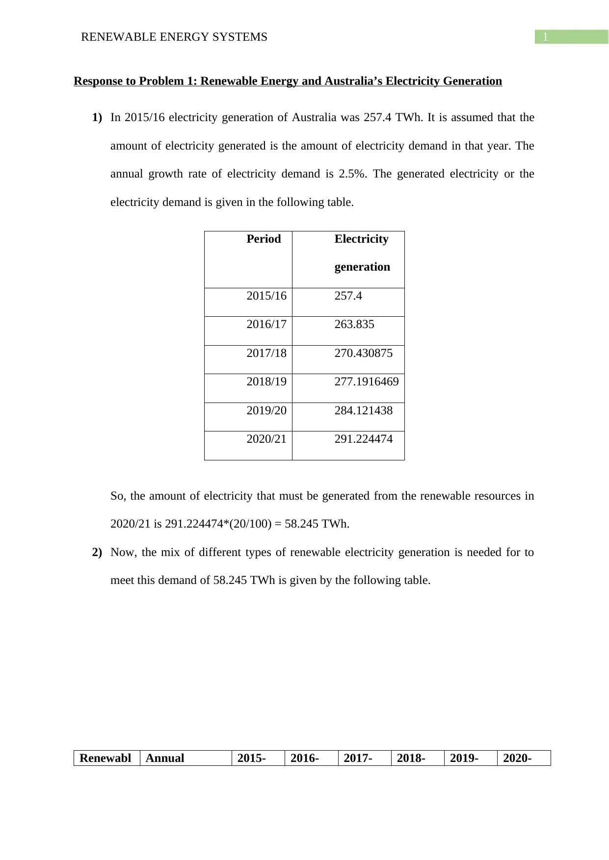
1) In 2015/16 electricity generation of Australia was 257.4 TWh. It is assumed that the
amount of electricity generated is the amount of electricity demand in that year. The
annual growth rate of electricity demand is 2.5%. The generated electricity or the
electricity demand is given in the following table.
Period Electricity
generation
2015/16 257.4
2016/17 263.835
2017/18 270.430875
2018/19 277.1916469
2019/20 284.121438
2020/21 291.224474
So, the amount of electricity that must be generated from the renewable resources in
2020/21 is 291.224474*(20/100) = 58.245 TWh.
2) Now, the mix of different types of renewable electricity generation is needed for to
meet this demand of 58.245 TWh is given by the following table.
Renewabl Annual 2015- 2016- 2017- 2018- 2019- 2020-
2RENEWABLE ENERGY SYSTEMS
es Growth
rate(%)
16(TW
h)
17(TW
h)
18(TW
h)
19(TW
h)
20(TW
h)
21(TW
h)
Hydro 13.90% 15.318 17.4472 19.8723
6
22.6346
2
25.7808
3
29.3643
7
Wind 6.40% 12.199 12.9797
4
13.8104
4
14.6943
1
15.6347
4
16.6353
7
Bioenergy 5.50% 3.79 3.99845 4.21836
5
4.45037
5
4.69514
5
4.95337
8
Solar PV 23.60% 6.838 8.45176
8
10.4463
9
12.9117
3
15.9589 19.7252
Total 70.6783
2
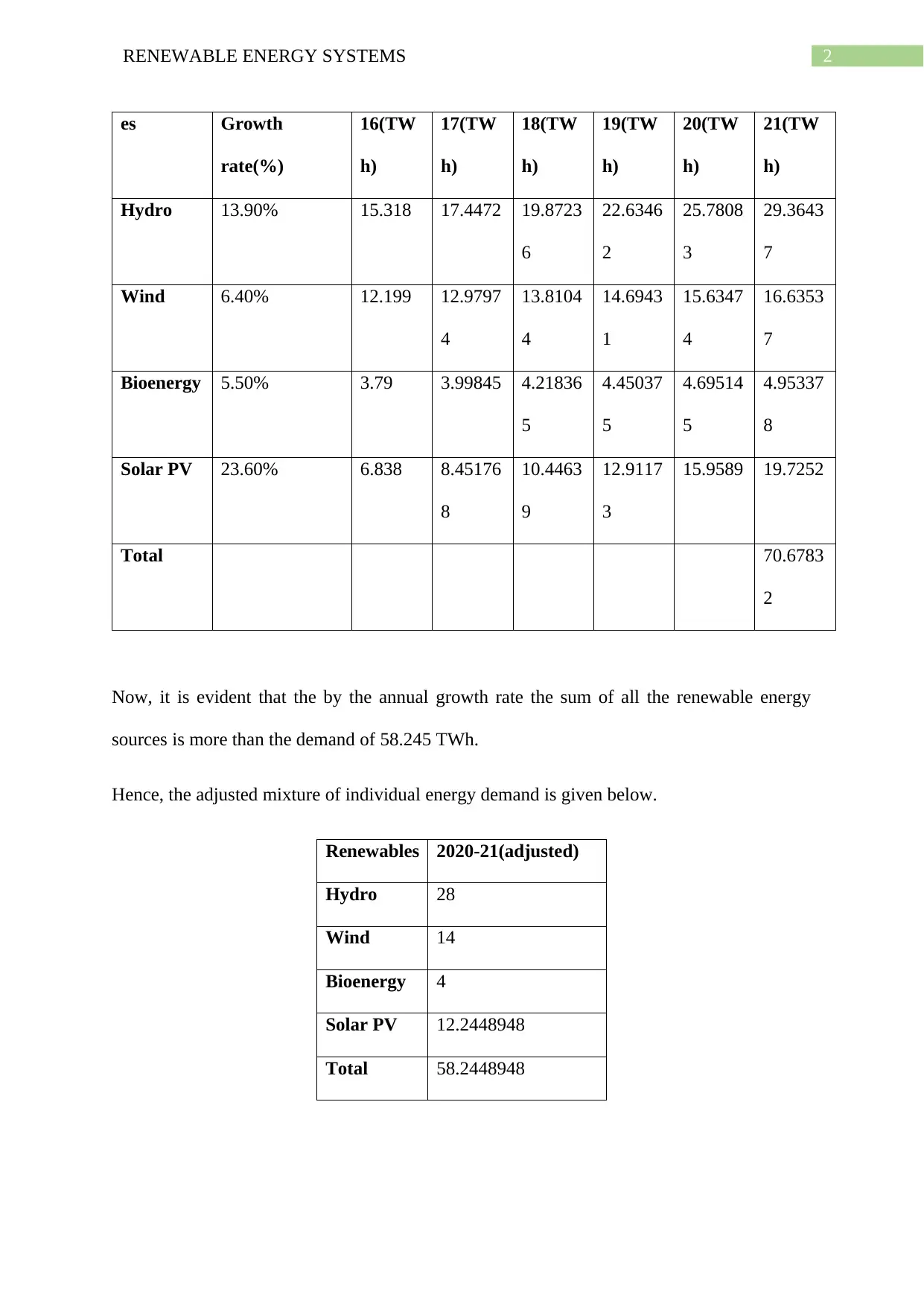
Now, it is evident that the by the annual growth rate the sum of all the renewable energy
sources is more than the demand of 58.245 TWh.
Hence, the adjusted mixture of individual energy demand is given below.
Renewables 2020-21(adjusted)
Hydro 28
Wind 14
Bioenergy 4
Solar PV 12.2448948
Total 58.2448948
⊘ This is a preview!⊘
Do you want full access?
Subscribe today to unlock all pages.

Trusted by 1+ million students worldwide
3RENEWABLE ENERGY SYSTEMS
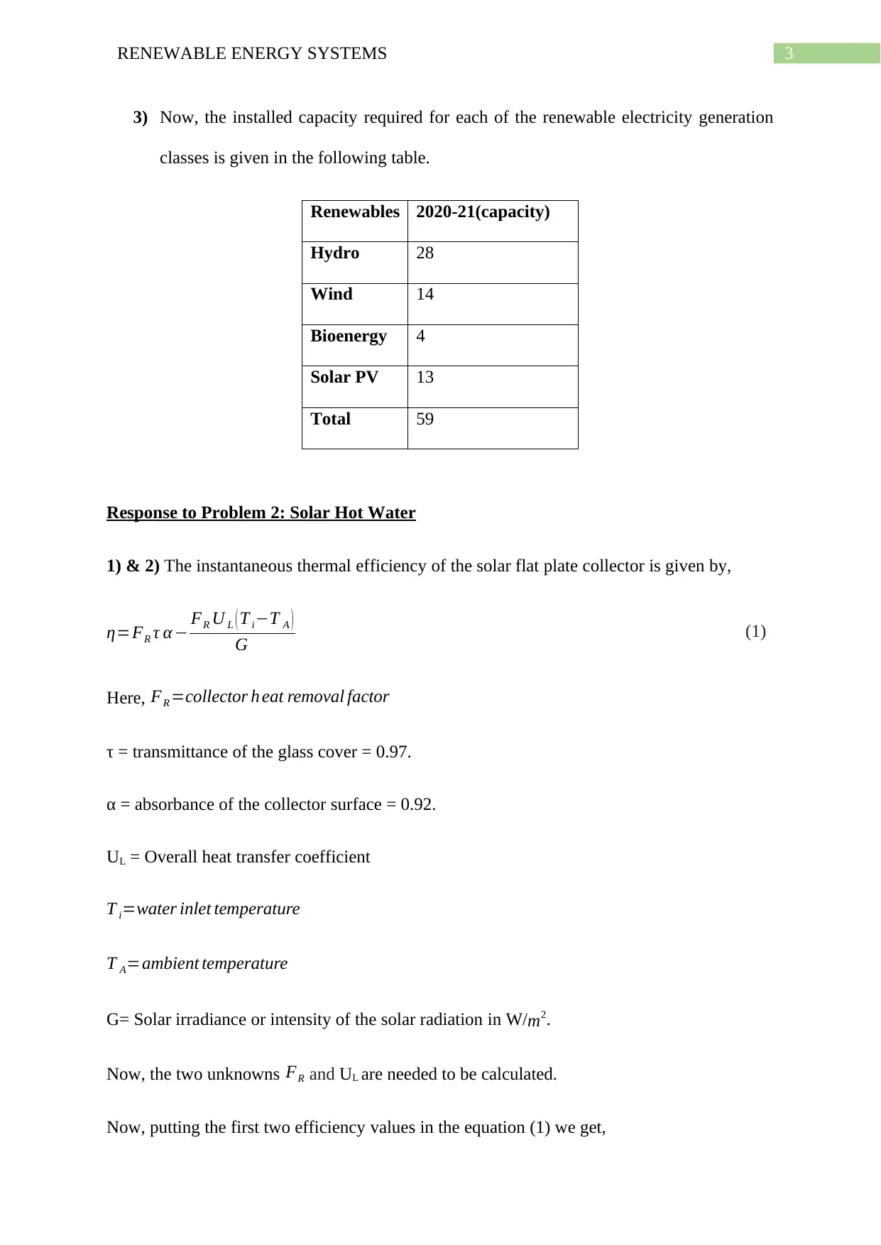
3) Now, the installed capacity required for each of the renewable electricity generation
classes is given in the following table.
Renewables 2020-21(capacity)
Hydro 28
Wind 14
Bioenergy 4
Solar PV 13
Total 59
Response to Problem 2: Solar Hot Water
1) & 2) The instantaneous thermal efficiency of the solar flat plate collector is given by,
η=FR τ α − FR U L ( T i−T A )
G (1)
Here, FR =collector h eat removal factor
τ = transmittance of the glass cover = 0.97.
α = absorbance of the collector surface = 0.92.
UL = Overall heat transfer coefficient
T i=water inlet temperature
T A=ambient temperature
G= Solar irradiance or intensity of the solar radiation in W/ m2.
Now, the two unknowns FR and UL are needed to be calculated.
Now, putting the first two efficiency values in the equation (1) we get,
Paraphrase This Document
Need a fresh take? Get an instant paraphrase of this document with our AI Paraphraser
4RENEWABLE ENERGY SYSTEMS
0.72 = FR 0.97∗0.92−FR∗U L 0.014 (2)
0.71 = FR 0.97∗0.92−FR∗U L*0.0175 (3)
Now, solving the equations (2) and (3) we get,
0.72
0.97∗0.92−U L 0.014 = 0.71
0.97∗0.92 – UL∗0.0175
0.6425−¿0.0126U L = 0.6336 – 0.00994U L
U L = 3.346 W
m2 K
Now, putting the value of UL in equation (2) we get,
FR =0.72/(0.97∗0.92−3.346∗0.014) = 0.8515
So, the heat removal factor is 0.8515 and the overall heat transfer coefficient is 3.346
W
m2 K .
3) The rate at which the collector can deliver the useful energy is given by the useful energy
gain divided by the collector area.
Now, the power output from the collector is given by,
QU
A =F R ( G τ α −UL ( Ti−T A ) )
Now, FR =¿0.8515, G = 750 W/ m2, T A=15 ° C=288 K ,T i=28 ° C=301 K, U L = 3.346 W
m2 K ,
α = 0.92, τ = 0.97
QU
A =¿0.8515(750*0.97*0.92 – 3.346(301-288)) = 532.87 W/m^2
Hence, the power output from the collector is 532.87 W/m^2.
5RENEWABLE ENERGY SYSTEMS
4) Now, the stagnation temperature is the maximum temperature difference between the
ambient and the water inlet temperature when the useful energy can’t be removed from the
collector. This is basically the intercept of the Efficiency vs ( Ti −T A )
G curve with the ( Ti −T A )
G
axis. Hence, by the condition of the question (3) the stagnation temperature is 28-15 = 13 ° C .
Response to problem 3:
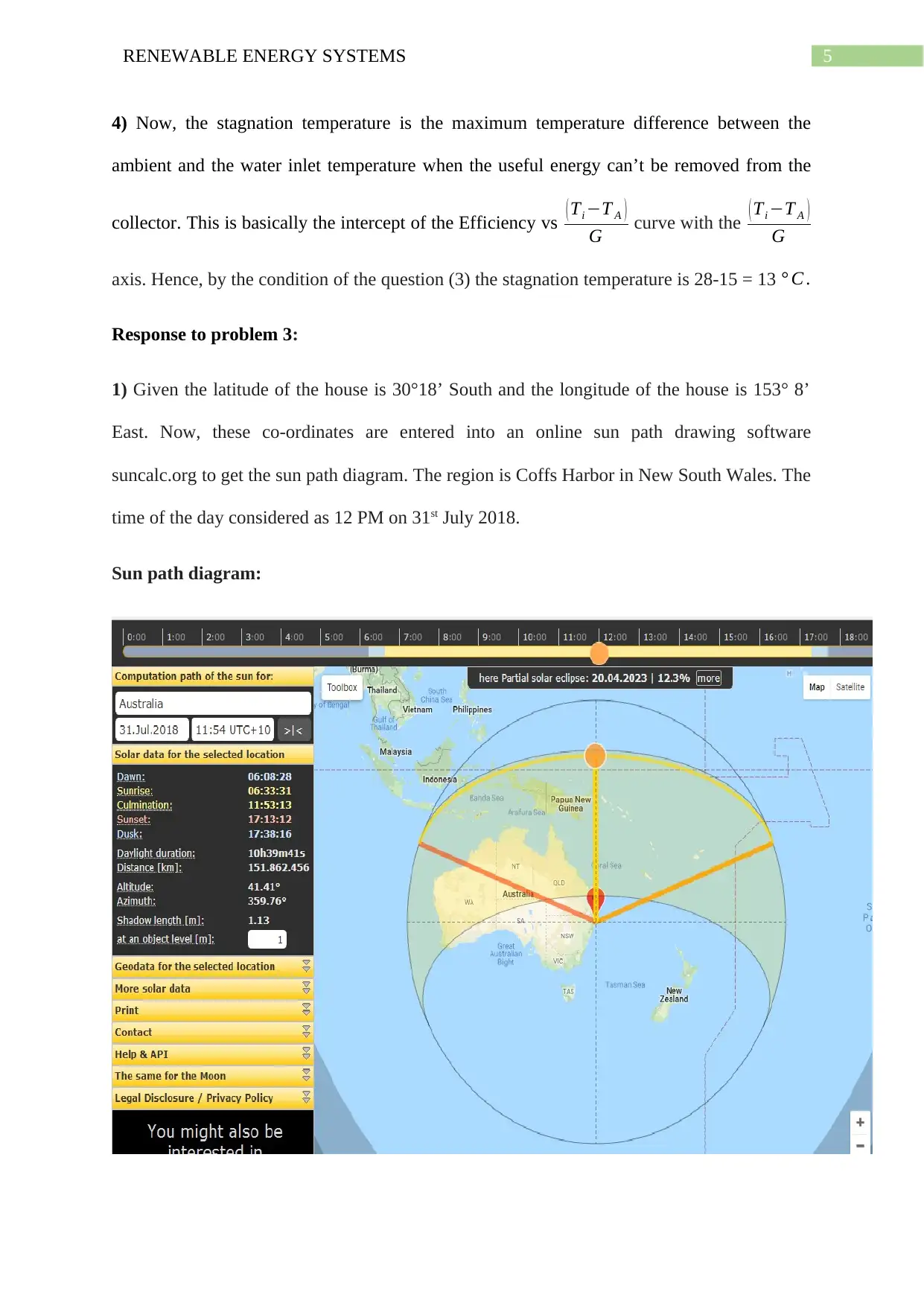
1) Given the latitude of the house is 30°18’ South and the longitude of the house is 153° 8’
East. Now, these co-ordinates are entered into an online sun path drawing software
suncalc.org to get the sun path diagram. The region is Coffs Harbor in New South Wales. The
time of the day considered as 12 PM on 31st July 2018.
Sun path diagram:
⊘ This is a preview!⊘
Do you want full access?
Subscribe today to unlock all pages.

Trusted by 1+ million students worldwide
6RENEWABLE ENERGY SYSTEMS
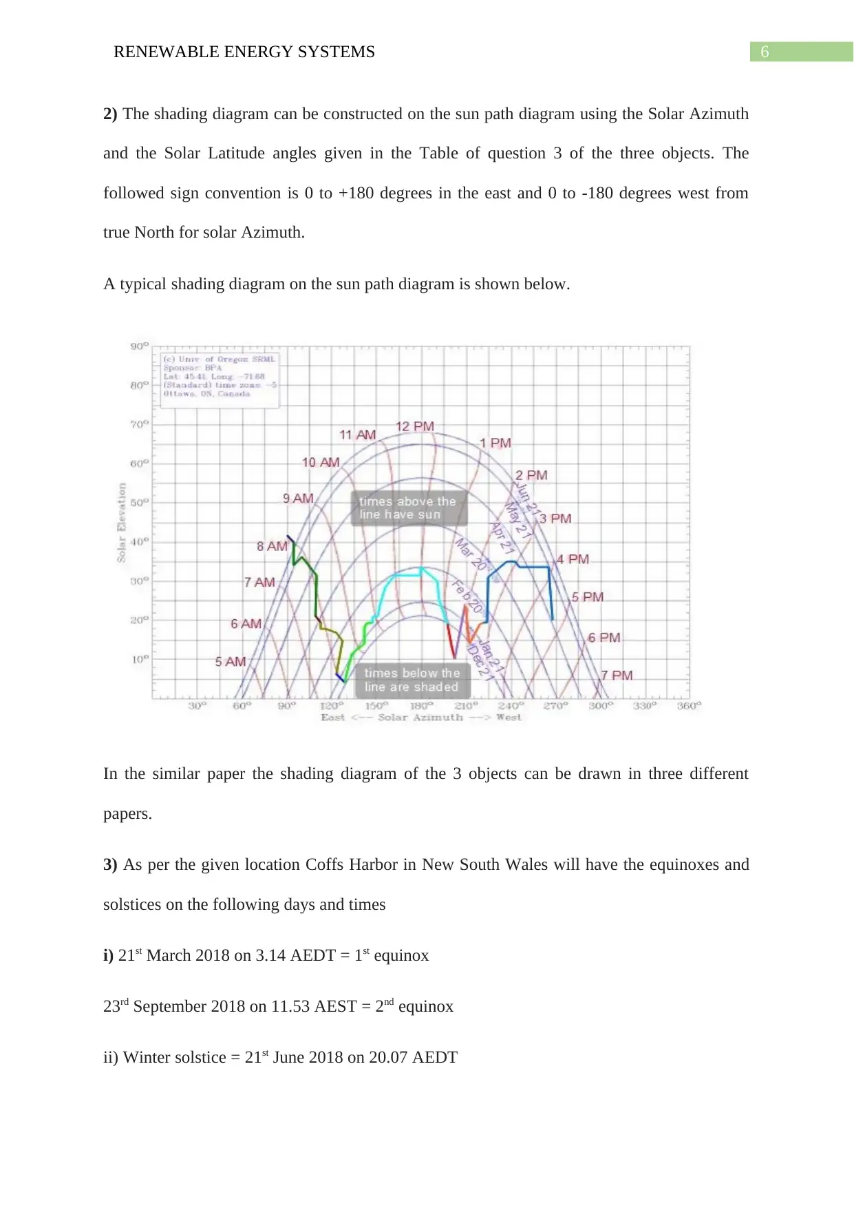
2) The shading diagram can be constructed on the sun path diagram using the Solar Azimuth
and the Solar Latitude angles given in the Table of question 3 of the three objects. The
followed sign convention is 0 to +180 degrees in the east and 0 to -180 degrees west from
true North for solar Azimuth.
A typical shading diagram on the sun path diagram is shown below.
In the similar paper the shading diagram of the 3 objects can be drawn in three different
papers.
3) As per the given location Coffs Harbor in New South Wales will have the equinoxes and
solstices on the following days and times
i) 21st March 2018 on 3.14 AEDT = 1st equinox
23rd September 2018 on 11.53 AEST = 2nd equinox
ii) Winter solstice = 21st June 2018 on 20.07 AEDT
Paraphrase This Document
Need a fresh take? Get an instant paraphrase of this document with our AI Paraphraser
7RENEWABLE ENERGY SYSTEMS
iii) Summer solstice = 22nd December 2018 on 9.22 AEDT
It should be noted that as Australia is in southern hemisphere, so the summer months are
December to February and winter months are June to August.
Response to problem 4:
1) From the table of Question 4 it clear that the major renewable energy resource which is
used in the current time i.e. in 2012-13 is Bagasse. The amount of energy produced from
Bagasse is 95.3 Peta Joule.
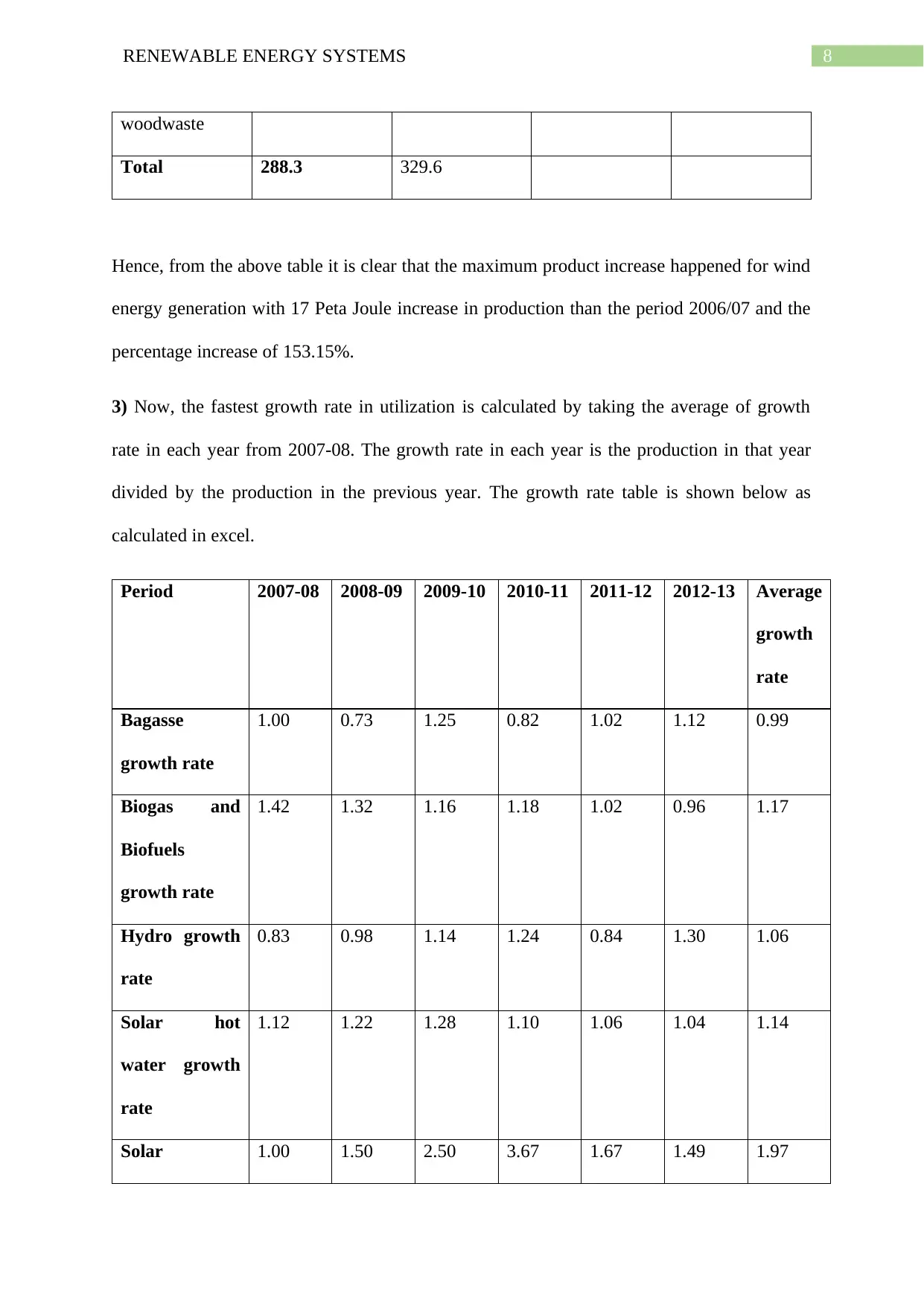
2) The renewable energy resource that has the largest increase in the production from the
period 2006/07 to 2012/13 is found by subtracting the production in 2012/13 from 2006/07.
The result is given in the following table.
Renewable
energy
2006-07(Peta
Joule)
2012-13(Peta
Joule)
Production
increase
Percentage
increase
Bagasse 110.8 95.3 -15.5 -13.98916968
Biogas and
Biofuels
10.7 26.5 15.8 103.9473684
Hydro 52.3 65.8 13.5 31.10599078
Solar hot water 6 12.8 6.8 101.4925373
Solar electricity 0.4 13.7 13.3 3325
Wind 9.4 26.4 17 153.1531532
Wood and 98.7 89.1 -9.6 -9.726443769
8RENEWABLE ENERGY SYSTEMS
woodwaste
Total 288.3 329.6
Hence, from the above table it is clear that the maximum product increase happened for wind
energy generation with 17 Peta Joule increase in production than the period 2006/07 and the
percentage increase of 153.15%.
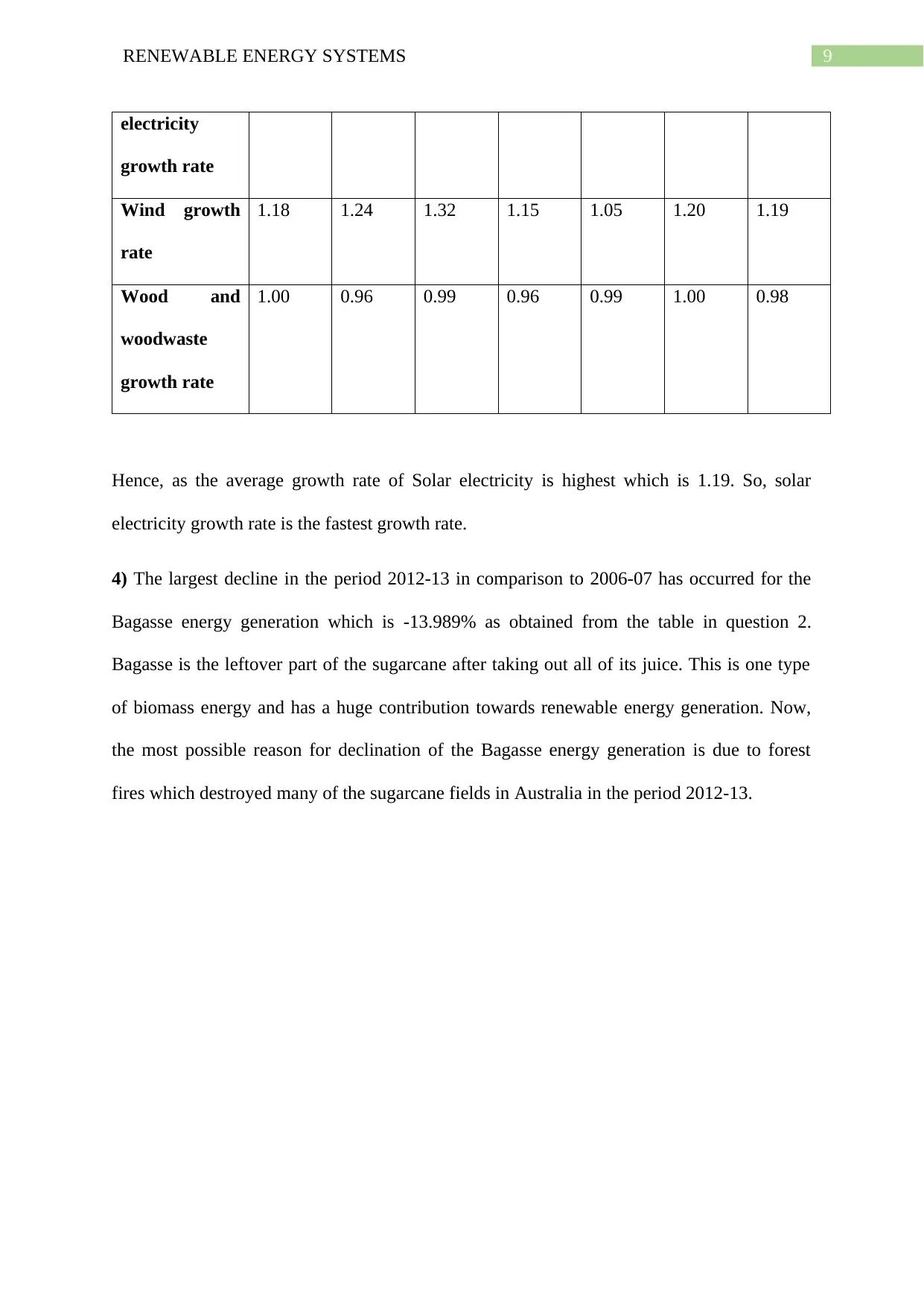
3) Now, the fastest growth rate in utilization is calculated by taking the average of growth
rate in each year from 2007-08. The growth rate in each year is the production in that year
divided by the production in the previous year. The growth rate table is shown below as
calculated in excel.
Period 2007-08 2008-09 2009-10 2010-11 2011-12 2012-13 Average
growth
rate
Bagasse
growth rate
1.00 0.73 1.25 0.82 1.02 1.12 0.99
Biogas and
Biofuels
growth rate
1.42 1.32 1.16 1.18 1.02 0.96 1.17
Hydro growth
rate
0.83 0.98 1.14 1.24 0.84 1.30 1.06
Solar hot
water growth
rate
1.12 1.22 1.28 1.10 1.06 1.04 1.14
Solar 1.00 1.50 2.50 3.67 1.67 1.49 1.97
⊘ This is a preview!⊘
Do you want full access?
Subscribe today to unlock all pages.

Trusted by 1+ million students worldwide
9RENEWABLE ENERGY SYSTEMS
electricity
growth rate
Wind growth
rate
1.18 1.24 1.32 1.15 1.05 1.20 1.19
Wood and
woodwaste
growth rate
1.00 0.96 0.99 0.96 0.99 1.00 0.98
Hence, as the average growth rate of Solar electricity is highest which is 1.19. So, solar
electricity growth rate is the fastest growth rate.
4) The largest decline in the period 2012-13 in comparison to 2006-07 has occurred for the
Bagasse energy generation which is -13.989% as obtained from the table in question 2.
Bagasse is the leftover part of the sugarcane after taking out all of its juice. This is one type
of biomass energy and has a huge contribution towards renewable energy generation. Now,
the most possible reason for declination of the Bagasse energy generation is due to forest
fires which destroyed many of the sugarcane fields in Australia in the period 2012-13.
1 out of 10
Your All-in-One AI-Powered Toolkit for Academic Success.
+13062052269
info@desklib.com
Available 24*7 on WhatsApp / Email
![[object Object]](/_next/static/media/star-bottom.7253800d.svg)
Unlock your academic potential
© 2024 | Zucol Services PVT LTD | All rights reserved.
