Enhancing Power Grid Performance Using CAES and Wind Turbine System
VerifiedAdded on 2022/10/04
|6
|2594
|21
Report
AI Summary
This report presents a comprehensive analysis of a parallel-connected compressed air energy storage (CAES) and wind turbine system designed to improve power grid performance. The study addresses the challenges of integrating wind energy into the grid, specifically the fluctuations caused by the intermittent nature of wind. The research utilizes Matlab Simulink to model and simulate the system, focusing on active power and grid voltage. The report includes a literature review, detailed research methods, data analysis, and expected outcomes. The findings demonstrate the effectiveness of the parallel CAES system in smoothing power fluctuations and maintaining a stable power supply to the grid. The study also explores the compression and expansion stages of the CAES system, including the use of compressors, heat exchangers, and turbines. The results indicate that the parallel CAES configuration significantly reduces wind power fluctuations and maintains constant power generation, providing valuable insights into enhancing the reliability of renewable energy sources.

Abstract- Over recent days, there have been a lot
of concerns on the greenhouse emission levels. The
emissions have over the past been; largely
contributed by the manner in which energy is being
harness, or technically termed as the use of no
renewable sources of energy. However, wind energy
provides more formidable options, whereby it is
renewable and can be continuously tapped, without
getting depleted or causing harm to the
environment. Nonetheless, there is the likeliness of
the quality of the grid system getting affected by the
high stochastic nature of the wind. Normally, the
fluctuations have an overall effect on the
performance of the grid, and compressed air energy
storage tends to be e a great solution towards the
same. In this research plan, a comprehensive
review and analysis of the proposed methodology
are provided, which details the steps as well as the
modeling involved in ensuring that the intermittent
and fluctuations issues associated with wind energy
are solved. To determine the effectiveness of the
systems, Matlab Simulink needs to be utilized. In
the provided plan, the major areas of focus include
the active power and the grids voltage. The results
demonstrated by the experiment shows that the
proposed methodology significantly smoothened out
the power fluctuations and provided an expected
output of the power supply to the voltage grid
system.
i. INTRODUCTION
Energy generation is one of the major issues
which have a crucial influence on the technological
advancements as well as developments. However,
issues of sustainability have to be put into place
whenever we are harvesting energy. In the past, most
of the technologies applied are those which only
attempt to favor no- renewable sources of energy.
This resulted so much in a jeopardy in the side of the
renewable sources of energy such as wind and solar.
Consequently, there are factors which were mainly
pointed out, for instance, issues to do with power
fluctuations and intermittency issues in the wind
energy. A number of approaches have been put into
place in the past, for instance; adjusting the rotation
speed of the wind power generator, adjusting the
pitch angle, as well as incorporating an inverter
which converts the generated dc power into ac. As a
result of this, the research plan proposed a new
technique: a parallel-connected compressed air
energy storage and wind turbine system. The
technology comes with vast advantages when
compared to the other energy storage devices such as
battery and flywheel. By extension, the proposed
technology is associated with a longer life span,
which provides the appropriate solution to the energy
device storage requirements of a long life for the
purpose of charging and discharging of the energy.
Statistically, the growth of wind energy has been
positive in the years between 1996 and 2012. By way
of approximation, the European wind energy
association anticipates delivery of close to 15.7% of
the total demand for Europe's 230 gigawatts [1]. This
percentage is deemed to go up by 2030, with an
approximation of 28.5 %.
Research plan
Ideally, the research shall be in accordance with the
conventional methods of conducting research,
whereby a literature review shall be conducted in
relation to the various parts of the wind turbine which
requires modification. After that, data analysis shall
be conducted using various energy analysis s
software’s and then upon verification, a system
design shall proceed.
III. LITERATURE REVIEW
Improving Power Grid Performance Using
Parallel-Connected Compressed Air Energy
Storage and Wind Turbine System
Student Name and Student Number
Paraphrase This Document
Need a fresh take? Get an instant paraphrase of this document with our AI Paraphraser
Various authors have made publications in the past
which relates to the wind turbine. Their areas of
focus have been on the wind turbines as a technique
for harnessing the energy, and the utilization of
compressed air energy storage for the purposes of
smoothening the power output delivered into the rid
system. As per the authors [1], they delved into the
current technologies in the compressed air system
and then offered various recommendations which
will help in improving its performance in future
times. The authors went further to offer design, plan,
as well as the cost investments in the improved
compressed air storage system. Another author [2],
also performed modeling on the power input and
power output for the case of the air energy storage.
The main intention for his practical experiment was
to perform strict monitoring of the dynamics of the
compressed air storage. From the conclusion made y
the author, it is really not economical to utilize the
CAES in individual firms, as it is associated with
longer payback periods. However, when utilized on
the power output side, it is able to offer a
smoothening of the outputted signal.
Elsewhere, [3], conducted a feasibility study on the
possible integration of compressed air energy storage
system with wind hybrid system. By extension, a
mathematical model was established in that case
which monitored the response of the power output of
the hybrid wind coupled with the compressed air
energy storage. The obtained mathematical equation
realized was as shown below.
P = 0.5 paπr2t v3wc2p (1)
Where Pa represents the air density
Rt is the blade radius
Cp is the turbine efficiency
Vw is the wind speed
Finally, in [4], the authors provided a detailed
explanation of the causes of the power fluctuations
which arises while connecting the system grid with
the wind turbine. The authors generated an equation
for the modeling, wind power, as well as the
generator modeling
II. RESEARCH METHODS
Theory
Ordinarily, the wind turbine transfers the energy from
the wind into shaft mechanical energy which the gets
transformed into electrical energy y the help of an
electrical generator. The turbine set to be utilized in
this design case is rated 12m/s in terms of speed; this
will allow for compression to occur whenever the
speed of the wind is more than this value. However,
when the speed of wind is less than 12 m/s, the
compression will not take place and the air mass flow
rate getting into the storage tank shall only be storage
tank. The configuration in this paper is parallel
CAES, which is a modified version of the series
CAES. The modelling is such that whenever the
electricity cost goes down, the storage gets charged,
and whenever it heightens, it gets discharged. In
order to supply power to the generator, a comparison
of the two configurations is done.
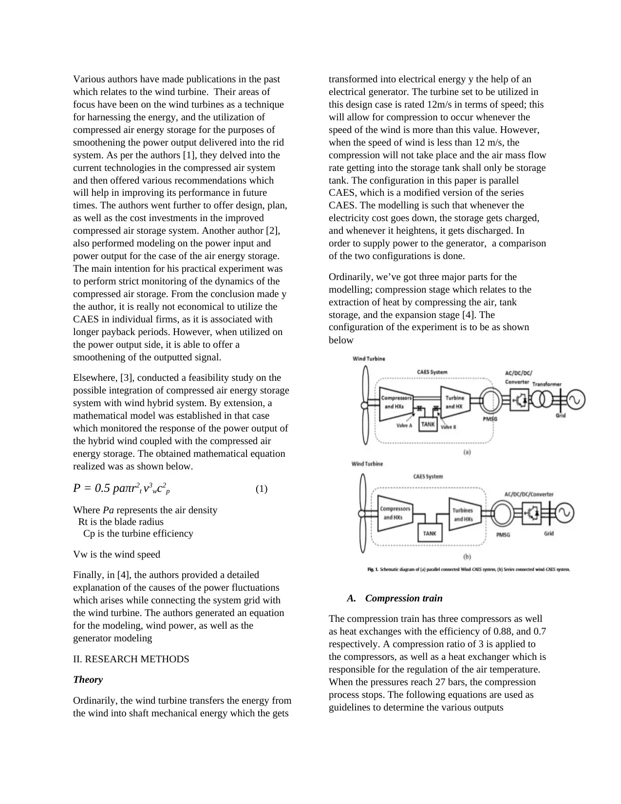
Ordinarily, we’ve got three major parts for the
modelling; compression stage which relates to the
extraction of heat by compressing the air, tank
storage, and the expansion stage [4]. The
configuration of the experiment is to be as shown
below
A. Compression train
The compression train has three compressors as well
as heat exchanges with the efficiency of 0.88, and 0.7
respectively. A compression ratio of 3 is applied to
the compressors, as well as a heat exchanger which is
responsible for the regulation of the air temperature.
When the pressures reach 27 bars, the compression
process stops. The following equations are used as
guidelines to determine the various outputs
which relates to the wind turbine. Their areas of
focus have been on the wind turbines as a technique
for harnessing the energy, and the utilization of
compressed air energy storage for the purposes of
smoothening the power output delivered into the rid
system. As per the authors [1], they delved into the
current technologies in the compressed air system
and then offered various recommendations which
will help in improving its performance in future
times. The authors went further to offer design, plan,
as well as the cost investments in the improved
compressed air storage system. Another author [2],
also performed modeling on the power input and
power output for the case of the air energy storage.
The main intention for his practical experiment was
to perform strict monitoring of the dynamics of the
compressed air storage. From the conclusion made y
the author, it is really not economical to utilize the
CAES in individual firms, as it is associated with
longer payback periods. However, when utilized on
the power output side, it is able to offer a
smoothening of the outputted signal.
Elsewhere, [3], conducted a feasibility study on the
possible integration of compressed air energy storage
system with wind hybrid system. By extension, a
mathematical model was established in that case
which monitored the response of the power output of
the hybrid wind coupled with the compressed air
energy storage. The obtained mathematical equation
realized was as shown below.
P = 0.5 paπr2t v3wc2p (1)
Where Pa represents the air density
Rt is the blade radius
Cp is the turbine efficiency
Vw is the wind speed
Finally, in [4], the authors provided a detailed
explanation of the causes of the power fluctuations
which arises while connecting the system grid with
the wind turbine. The authors generated an equation
for the modeling, wind power, as well as the
generator modeling
II. RESEARCH METHODS
Theory
Ordinarily, the wind turbine transfers the energy from
the wind into shaft mechanical energy which the gets
transformed into electrical energy y the help of an
electrical generator. The turbine set to be utilized in
this design case is rated 12m/s in terms of speed; this
will allow for compression to occur whenever the
speed of the wind is more than this value. However,
when the speed of wind is less than 12 m/s, the
compression will not take place and the air mass flow
rate getting into the storage tank shall only be storage
tank. The configuration in this paper is parallel
CAES, which is a modified version of the series
CAES. The modelling is such that whenever the
electricity cost goes down, the storage gets charged,
and whenever it heightens, it gets discharged. In
order to supply power to the generator, a comparison
of the two configurations is done.
Ordinarily, we’ve got three major parts for the
modelling; compression stage which relates to the
extraction of heat by compressing the air, tank
storage, and the expansion stage [4]. The
configuration of the experiment is to be as shown
below
A. Compression train
The compression train has three compressors as well
as heat exchanges with the efficiency of 0.88, and 0.7
respectively. A compression ratio of 3 is applied to
the compressors, as well as a heat exchanger which is
responsible for the regulation of the air temperature.
When the pressures reach 27 bars, the compression
process stops. The following equations are used as
guidelines to determine the various outputs
Toutc, a =β c (nc-1)/ nc Tinc, a
T outHX, a = T inHX, a + ηHX (T inHXF - T
inHX, a)
Poutc, a = Pinc, a βc
Pc, a = mccp Tinc, a (βc (nc-1) / nc -1)/nc
……………………………………………..(2)
Where
Bc- compression ratio of each compressor
nc- efficiency of each compressor
mc- mass flow rate cp- specific heat capacity
B. Tank modelling
The modelling of the tank entails various parameters
such as the power consumption from the compression
process, pressure, and temperature from the turbines
and compressors, and the power generated from the
expansion train [5]. The outputs generated includes
pressure and mass which are then used in
determining the temperature of the compressed air
using the below equations
m = ∫ mindt - = ∫ moutdt
p = R
V ∫ min . Tin dt - ∫ mout.dt
pv= mRT. ……………………………………….
(3)
where
R = Gas constant, (J/kg K)
v = Tank volume, (m3)
Tin = Temperature of heat exchanger from
compressor, (K)
Ts = Temperature inside tank, (K)
For the purposes of determining the mass flow rate
and the pressure present inside the tank, equations 8
and 9 are utilized. These equations are then translated
into MATLAB coding prior to linking to the stat
space block in the Matlab Simulink.
C. Expansion train
The expansion train utilizes a turbine of efficiency
0.92 as well as a heat exchanger of 0.7 with an
application of compression ratio of 20. The air which
has been compressed is to be allowed through the
heat exchanger, the equations below shows the
determination of the various outputs which are to be
fed in the MATLAB Simulink [6].
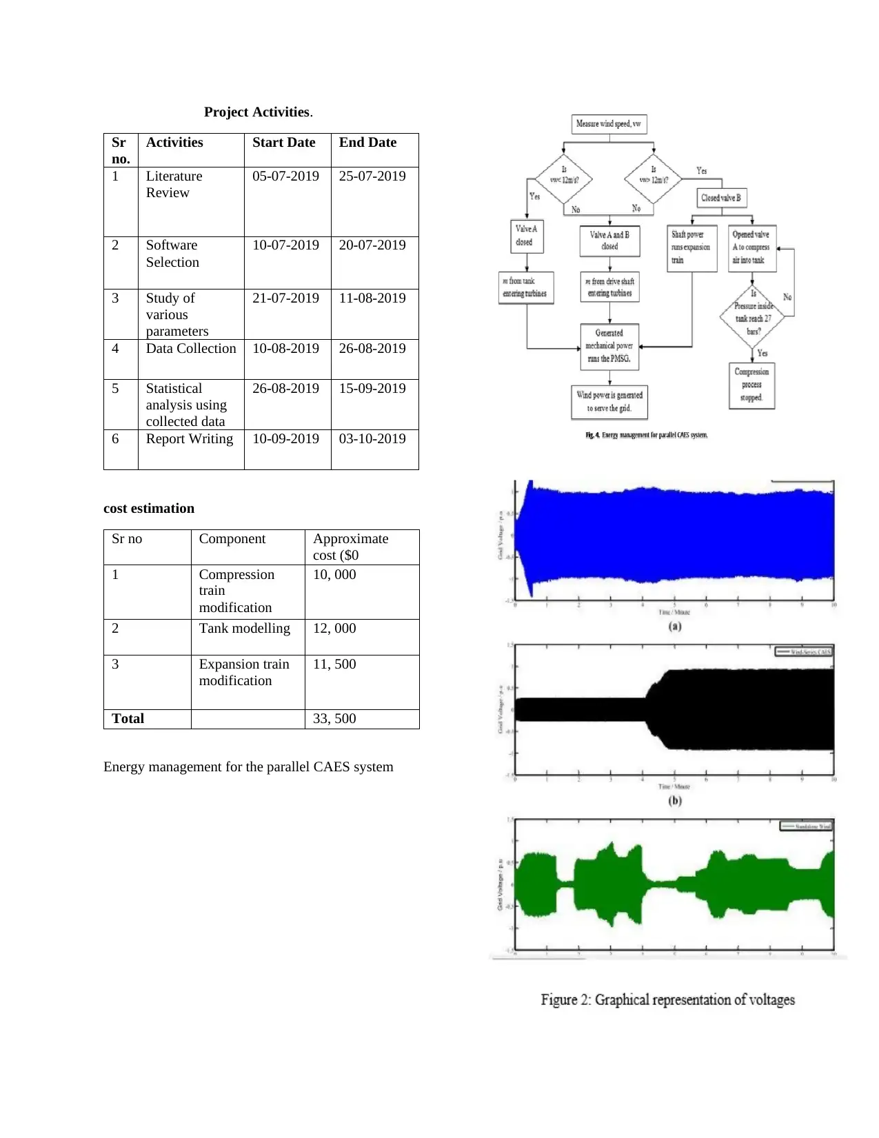
IV. DATA ANALYSIS
Valve operation.
Valve A
Valve
B
Above rated ON OFF
At rated OFF OFF
Below rated OFF ON
table 2
3 stage-
compression
process
2 stage-
compression
process
Expansion
process
324.79 341.97 e
302.54 307.69 e
3 5.2 e
335.36 359.12 e
305.71 312.84 e
9 27 e
338.88 e 380.9
T outHX, a = T inHX, a + ηHX (T inHXF - T
inHX, a)
Poutc, a = Pinc, a βc
Pc, a = mccp Tinc, a (βc (nc-1) / nc -1)/nc
……………………………………………..(2)
Where
Bc- compression ratio of each compressor
nc- efficiency of each compressor
mc- mass flow rate cp- specific heat capacity
B. Tank modelling
The modelling of the tank entails various parameters
such as the power consumption from the compression
process, pressure, and temperature from the turbines
and compressors, and the power generated from the
expansion train [5]. The outputs generated includes
pressure and mass which are then used in
determining the temperature of the compressed air
using the below equations
m = ∫ mindt - = ∫ moutdt
p = R
V ∫ min . Tin dt - ∫ mout.dt
pv= mRT. ……………………………………….
(3)
where
R = Gas constant, (J/kg K)
v = Tank volume, (m3)
Tin = Temperature of heat exchanger from
compressor, (K)
Ts = Temperature inside tank, (K)
For the purposes of determining the mass flow rate
and the pressure present inside the tank, equations 8
and 9 are utilized. These equations are then translated
into MATLAB coding prior to linking to the stat
space block in the Matlab Simulink.
C. Expansion train
The expansion train utilizes a turbine of efficiency
0.92 as well as a heat exchanger of 0.7 with an
application of compression ratio of 20. The air which
has been compressed is to be allowed through the
heat exchanger, the equations below shows the
determination of the various outputs which are to be
fed in the MATLAB Simulink [6].
IV. DATA ANALYSIS
Valve operation.
Valve A
Valve
B
Above rated ON OFF
At rated OFF OFF
Below rated OFF ON
table 2
3 stage-
compression
process
2 stage-
compression
process
Expansion
process
324.79 341.97 e
302.54 307.69 e
3 5.2 e
335.36 359.12 e
305.71 312.84 e
9 27 e
338.88 e 380.9
⊘ This is a preview!⊘
Do you want full access?
Subscribe today to unlock all pages.
Trusted by 1+ million students worldwide
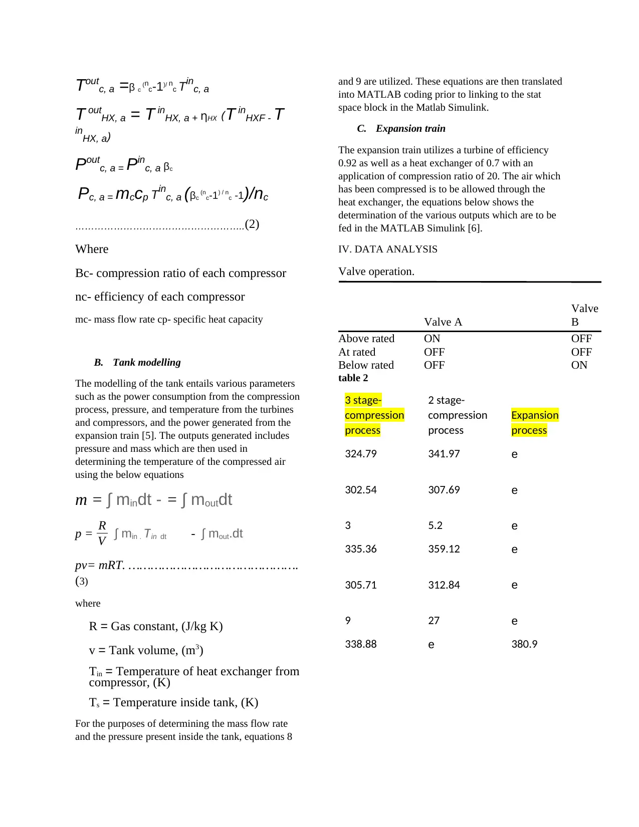
The changes, as well as observations in terms of
valuations which were recorded throughout the
experiment, is tabulated above [7]. Generally, we
have selected the voltage fluctuations as per terms of
reference. The difference in voltage for the system
was multiplied by 100% so as to generate the
fluctuation percentage. From the results obtained, the
lowest voltage fluctuations are experienced with the
parallel CAES [9]. The negative sign depicts that the
voltage of wind has been exceeded by 1pu. So long
as it was not beyond 10% of the 1 pu, then it was
within the grid requirement. The highest voltage
fluctuations seem to be experienced with the wind
conditions less than the rated value. At this moment,
the energy is not enough, thus overcoming the
fluctuations becomes very difficult.
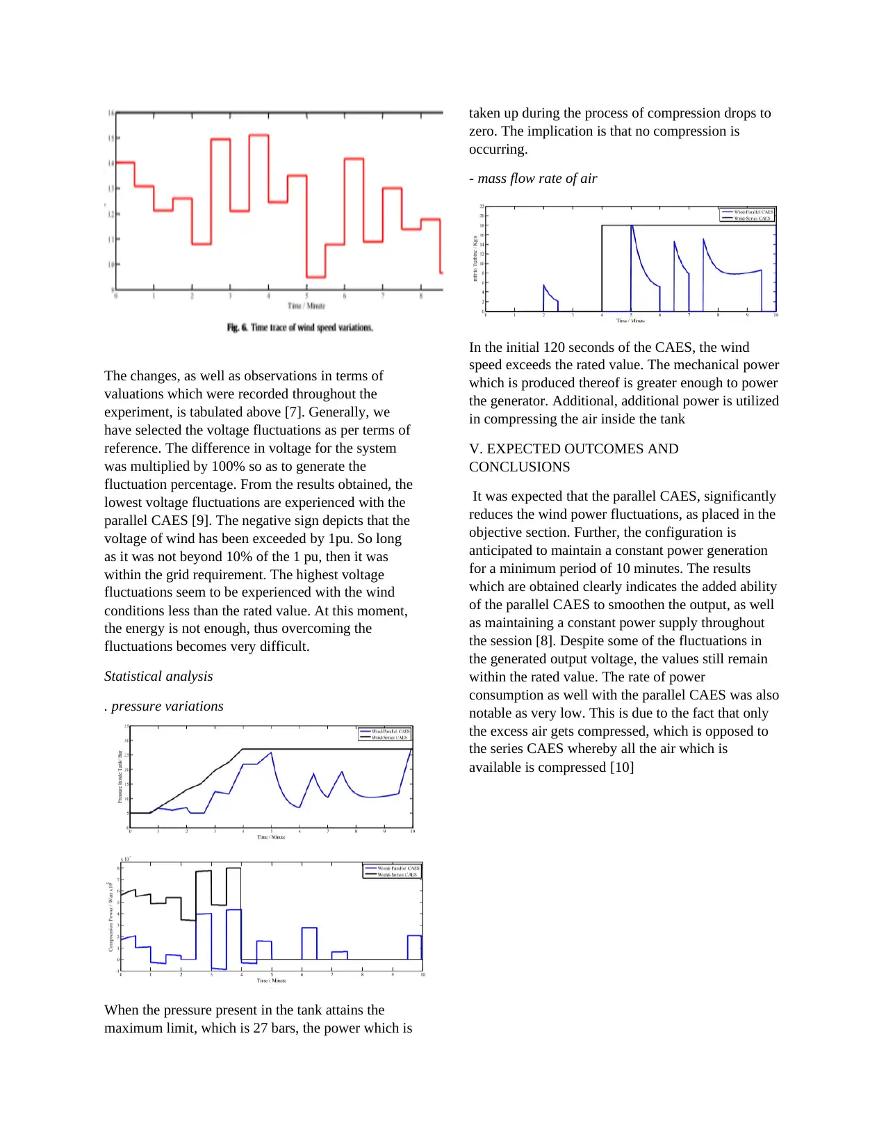
Statistical analysis
. pressure variations
When the pressure present in the tank attains the
maximum limit, which is 27 bars, the power which is
taken up during the process of compression drops to
zero. The implication is that no compression is
occurring.
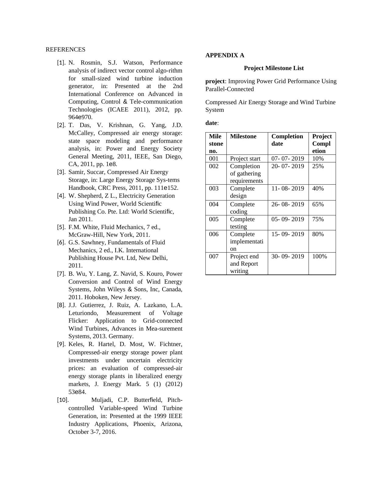
- mass flow rate of air
In the initial 120 seconds of the CAES, the wind
speed exceeds the rated value. The mechanical power
which is produced thereof is greater enough to power
the generator. Additional, additional power is utilized
in compressing the air inside the tank
V. EXPECTED OUTCOMES AND
CONCLUSIONS
It was expected that the parallel CAES, significantly
reduces the wind power fluctuations, as placed in the
objective section. Further, the configuration is
anticipated to maintain a constant power generation
for a minimum period of 10 minutes. The results
which are obtained clearly indicates the added ability
of the parallel CAES to smoothen the output, as well
as maintaining a constant power supply throughout
the session [8]. Despite some of the fluctuations in
the generated output voltage, the values still remain
within the rated value. The rate of power
consumption as well with the parallel CAES was also
notable as very low. This is due to the fact that only
the excess air gets compressed, which is opposed to
the series CAES whereby all the air which is
available is compressed [10]
valuations which were recorded throughout the
experiment, is tabulated above [7]. Generally, we
have selected the voltage fluctuations as per terms of
reference. The difference in voltage for the system
was multiplied by 100% so as to generate the
fluctuation percentage. From the results obtained, the
lowest voltage fluctuations are experienced with the
parallel CAES [9]. The negative sign depicts that the
voltage of wind has been exceeded by 1pu. So long
as it was not beyond 10% of the 1 pu, then it was
within the grid requirement. The highest voltage
fluctuations seem to be experienced with the wind
conditions less than the rated value. At this moment,
the energy is not enough, thus overcoming the
fluctuations becomes very difficult.
Statistical analysis
. pressure variations
When the pressure present in the tank attains the
maximum limit, which is 27 bars, the power which is
taken up during the process of compression drops to
zero. The implication is that no compression is
occurring.
- mass flow rate of air
In the initial 120 seconds of the CAES, the wind
speed exceeds the rated value. The mechanical power
which is produced thereof is greater enough to power
the generator. Additional, additional power is utilized
in compressing the air inside the tank
V. EXPECTED OUTCOMES AND
CONCLUSIONS
It was expected that the parallel CAES, significantly
reduces the wind power fluctuations, as placed in the
objective section. Further, the configuration is
anticipated to maintain a constant power generation
for a minimum period of 10 minutes. The results
which are obtained clearly indicates the added ability
of the parallel CAES to smoothen the output, as well
as maintaining a constant power supply throughout
the session [8]. Despite some of the fluctuations in
the generated output voltage, the values still remain
within the rated value. The rate of power
consumption as well with the parallel CAES was also
notable as very low. This is due to the fact that only
the excess air gets compressed, which is opposed to
the series CAES whereby all the air which is
available is compressed [10]
Paraphrase This Document
Need a fresh take? Get an instant paraphrase of this document with our AI Paraphraser
REFERENCES
[1]. N. Rosmin, S.J. Watson, Performance
analysis of indirect vector control algo-rithm
for small-sized wind turbine induction
generator, in: Presented at the 2nd
International Conference on Advanced in
Computing, Control & Tele-communication
Technologies (ICAEE 2011), 2012, pp.
964e970.
[2]. T. Das, V. Krishnan, G. Yang, J.D.
McCalley, Compressed air energy storage:
state space modeling and performance
analysis, in: Power and Energy Society
General Meeting, 2011, IEEE, San Diego,
CA, 2011, pp. 1e8.
[3]. Samir, Succar, Compressed Air Energy
Storage, in: Large Energy Storage Sys-tems
Handbook, CRC Press, 2011, pp. 111e152.
[4]. W. Shepherd, Z L., Electricity Generation
Using Wind Power, World Scientific
Publishing Co. Pte. Ltd: World Scientific,
Jan 2011.
[5]. F.M. White, Fluid Mechanics, 7 ed.,
McGraw-Hill, New York, 2011.
[6]. G.S. Sawhney, Fundamentals of Fluid
Mechanics, 2 ed., I.K. International
Publishing House Pvt. Ltd, New Delhi,
2011.
[7]. B. Wu, Y. Lang, Z. Navid, S. Kouro, Power
Conversion and Control of Wind Energy
Systems, John Wileys & Sons, Inc, Canada,
2011. Hoboken, New Jersey.
[8]. J.J. Gutierrez, J. Ruiz, A. Lazkano, L.A.
Leturiondo, Measurement of Voltage
Flicker: Application to Grid-connected
Wind Turbines, Advances in Mea-surement
Systems, 2013. Germany.
[9]. Keles, R. Hartel, D. Most, W. Fichtner,
Compressed-air energy storage power plant
investments under uncertain electricity
prices: an evaluation of compressed-air
energy storage plants in liberalized energy
markets, J. Energy Mark. 5 (1) (2012)
53e84.
[10]. Muljadi, C.P. Butterfield, Pitch-
controlled Variable-speed Wind Turbine
Generation, in: Presented at the 1999 IEEE
Industry Applications, Phoenix, Arizona,
October 3-7, 2016.
APPENDIX A
Project Milestone List
project: Improving Power Grid Performance Using
Parallel-Connected
Compressed Air Energy Storage and Wind Turbine
System
date:
Mile
stone
no.
Milestone Completion
date
Project
Compl
etion
001 Project start 07- 07- 2019 10%
002 Completion
of gathering
requirements
20- 07- 2019 25%
003 Complete
design
11- 08- 2019 40%
004 Complete
coding
26- 08- 2019 65%
005 Complete
testing
05- 09- 2019 75%
006 Complete
implementati
on
15- 09- 2019 80%
007 Project end
and Report
writing
30- 09- 2019 100%
Project Activities.
Sr
no.
Activities Start Date End Date
1 Literature
Review
05-07-2019 25-07-2019
2 Software
Selection
10-07-2019 20-07-2019
3 Study of
various
parameters
21-07-2019 11-08-2019
4 Data Collection 10-08-2019 26-08-2019
5 Statistical
analysis using
collected data
26-08-2019 15-09-2019
6 Report Writing 10-09-2019 03-10-2019
cost estimation
Sr no Component Approximate
cost ($0
1 Compression
train
modification
10, 000
2 Tank modelling 12, 000
3 Expansion train
modification
11, 500
Total 33, 500
Energy management for the parallel CAES system
⊘ This is a preview!⊘
Do you want full access?
Subscribe today to unlock all pages.
Trusted by 1+ million students worldwide
1 out of 6
Related Documents


Your All-in-One AI-Powered Toolkit for Academic Success.
+13062052269
info@desklib.com
Available 24*7 on WhatsApp / Email
![[object Object]](/_next/static/media/star-bottom.7253800d.svg)
Unlock your academic potential
Copyright © 2020–2026 A2Z Services. All Rights Reserved. Developed and managed by ZUCOL.