University Name - Microwave Communication Systems: RFID Report
VerifiedAdded on 2020/04/21
|24
|6013
|188
Report
AI Summary
This report provides a detailed overview of Radio Frequency Identification (RFID) systems, focusing on the application of Ultra High Frequency (UHF) and Super High Frequency (SHF) technologies in microwave communication. The report delves into the fundamental concepts of RFID, including the components like tags and readers, and their functions. It explores the advantages of UHF and SHF RFID, particularly the use of dual antenna structures for enhanced signal reading and data storage capabilities, including the ability to store more data than barcodes. The report presents a case study of a dual-band antenna design, including block diagrams, system implementation, and types, highlighting the strengths and drawbacks of these systems. It also includes a comparison between different RFID systems. The report also covers limitations such as cost, privacy concerns, and standardization challenges. The findings, conclusions, and recommendations offer insights into the performance, applications, and future of UHF and SHF RFID technologies.

Running head: MICROWAVE COMMUNICATION SYSTEMS
Microwave Communication Systems
Name of Student-
Name of University-
Author Note-
Microwave Communication Systems
Name of Student-
Name of University-
Author Note-
Paraphrase This Document
Need a fresh take? Get an instant paraphrase of this document with our AI Paraphraser
1MICROWAVE COMMUNICATION SYSTEMS
Abstract
The devices with Radio Frequency Identification have a small antenna and chip. The chip that is
used in RFID usually has a capability to carry 2000 bytes or less data in them. The work of RFID
is same as the barcode or same as the magnetic strip that is present in the back of an ATM card
or a credit card. The RFID tag provides an identifier that is unique for the object that it works on.
Same like barcodes and magnetic strips are scanned to get all the information, the tag f RFID is
also scanned so that the information can be identified. There are many advantages of using
Upper High Frequency and Super High Frequency in RFID. RFID has an advantage that they can
be placed precisely along with the scanner. The RFID reader and tags can be handled easily
which is not the case in magnetic tape and barcode scanner. This report presents a detail structure
of RFID device with a case study of UHF and SHF.
2MICROWAVE COMMUNICATION SYSTEMS
Table of Contents
Abstract................................................................................................................................1
Chapter 1: Introduction........................................................................................................2
1.1 Background of the Study...........................................................................................2
1.2 The Rationale.............................................................................................................3
1.3 Scope and Limitation.................................................................................................4
Chapter 2: Discussion..........................................................................................................6
2.1 Block Diagram...........................................................................................................6
2.2 System Implementation and Types............................................................................8
2.3 Strengths..................................................................................................................12
2.4 Drawbacks...............................................................................................................12
2.5 Comparison..............................................................................................................13
Chapter 3: Results of Research..........................................................................................14
3.1 Findings...................................................................................................................14
3.2 Conclusion...............................................................................................................15
3.3 Recommendation.....................................................................................................16
References..........................................................................................................................17
⊘ This is a preview!⊘
Do you want full access?
Subscribe today to unlock all pages.
Trusted by 1+ million students worldwide
3MICROWAVE COMMUNICATION SYSTEMS
Chapter 1: Introduction
1.1 Background of the Study
The most adopted technology that is widely used is the RFID (Radio Frequency
Identification) technology that is used for tracking goods and objects in logistics and supply
chain applications. The RFID technology has two devices in the system. One part is an
interrogator or a reader which has interrogation and energization function (Ariff, Ismarani and
Shamsuddin 2014). The second part is a transponder or a tag which is attached to the objects and
transmits the data back to the reader. The tag of RFID also has two parts: a RFID chip and
antenna. This report mainly consists of two RFID systems of UHF (Ultra High Frequency) and
SHF (Super High Frequency).
UHF tags of RFID do not have power source which is on board instead of using antenna
for harvesting energy from RF reader field and to activate the circuitry (Bagirathi and Sankar
2017). Passive tags of UHF do not transfer new power instead of reflecting back to reader the
continuous wave that is received by changing the impedance of the antenna. The antenna tag
should be very efficient and should be matched properly to chip so that the harvested power is
maximized and also achieve a range up to 10 meters (Bashir et al. 2017). Active tags mainly
have SHF frequencies ranging between 433 MHz to 915 MHz. Environmental considerations,
tag selection and user preference mainly dictates which application uses which frequency.
Generally RFID systems which operate on 433 MHz are favored by companies because of its
long wavelength. The long wave lengths enables to work better with water and metal.
Paraphrase This Document
Need a fresh take? Get an instant paraphrase of this document with our AI Paraphraser
4MICROWAVE COMMUNICATION SYSTEMS
In this digitization era, the use of Radio Frequency Identification (RFID) is fast growing
because it has many advantages with comparison to Auto-IDs. As discussed above, the system of
RFID has two parts known as tag and the reader (Bibi et al. 2017). The main function of the
RFID system is to retrieve all the information automatically with the help of reader which is
stored in the tag previously. There are also some limitations of using RFID tag as the tags have
single antenna which is used for backscattering and receiving (Chambe et al. 2014). The chip
that is present in the tag changes the impedance between the complex values and short circuit
value which modulates the signal that is back scatterer according to which the information is
stored inside the chip alternatively.
The antenna does not receive any kind of power from reader during short circuit (Dakir et
al. 2017). For this reason, the efficiency of energy absorption continues to drop significantly.
Two impedance short circuit and the conjugate matched in the short circuit phase, the status will
not provide maximum difference in impedance in backscattered signals that results in read the
signals in shorter range. This problem of RFID has also been mitigated. The process of short
circuit is mitigated by implementing dual structure of antenna. In a single RFID chip, a dual
antenna structure is incorporated (Donno, Catarinucci and Tarricone 2014). With the
incorporation of dual antenna, all the signals are utilized for backscattering and receiving the
operations separately. In many of the antennas of RFID tags, UHF (Ultra High Frequency) and
SHF (Super High Frequency) bands are proposed (Ding et al. 2014). In some of the systems,
convectional antennas that are single are used and others uses dual antenna.
1.2 The Rationale
The most significant advantage of Radio Frequency Identification using UHF and SHF is
that they can uses dual structure of antenna which allows the signal to read data from far away.
5MICROWAVE COMMUNICATION SYSTEMS
There are mainly two types of UHF; active UHF and passive UHF. Passive UHF can read data
across rooms also. The active and passive tags which are battery assisted can read the data in the
tags across buildings and also in environment which has difficult Radio Frequency (Fernández-
Caramés et al. 2016). The amount of data that a RFID tag stores is 100 times more than the data
that are stored in barcodes. This allows to keep more data tracks that is needed in inventory
which includes lot number, serial number, details of manufacturer, user, location of production,
vendor, date of expiration and many more details of the product that is needed.
In this report, there is an elaborated study about the use of Ultra High Frequency and
Super High Frequency in Radio Frequency Identification applications. There are many advantage
and disadvantages of using RFID in any applications (Huber et al. 2014). Those strength and
drawbacks are elaborately described in this report. There are certain limitations of using UTF
and STF in RFID applications which are researched in this report. Some case studies are
mentioned as an example of UTF and STF to have details about the topic. Some recommendation
as well as conclusion about using UTF and STF is studied in this report.
1.3 Scope and Limitation
Scope: The systems of barcode are mainly used for keeping the information of the
product, cost, inventory control and many more. But these systems have some drawbacks when
compared with RFID (Itoh and Machida 2014). The barcode stores very less amount of data as
compared with RFID. Approximately 1000 bytes data can be stored in Radio Frequency
Identification tags. The RFID tags using UTF and STF are mainly specific to each of the items,
but barcodes are not specific. For handling the barcode system, human interaction is needed.
Barcode needs access of time of sight to optical scanner for information that is product related
(Jeon et al. 2017). If the information that is stored in the barcode is to be modified, then the
⊘ This is a preview!⊘
Do you want full access?
Subscribe today to unlock all pages.
Trusted by 1+ million students worldwide
6MICROWAVE COMMUNICATION SYSTEMS
whole barcode is to be replaced which is not the case using RFID. The data can be modified in
the supply chain in RFID by an interaction between reader and microchip. The system of barcode
is not accurate as RFID. To use RFID in most of the systems enables easy handling of the system
and the scope of storing data is also high.
Limitation: As there is great potential in the system of RFID in local sector, there are
also some limitations of using RFID tag. The main drawback is the cost of the RFID tag. When
compared to other sector in the logistics group, the cost of RFID tag is much higher than other
systems such as barcode system. The leaders of industrial sector are mainly concerned about the
investment return and also the net profit by making more investment of the extra cost in the
system (Kamalvand, Pandey and Meshram 2016). The amount of volume that is used in the
system is depended on cost. The lowest cost that is available is low as 7.2 cents and 10 million in
volume and units respectively. The RFID tag is about 30 to 40 cents for smaller volume whereas
the cost of a barcode is about 4cents.
There is also limitation on the privacy and security of RFID system for the unauthorized
readers. The customer privacy faces a great challenge (Kibria, Islam and Yatim 2013). Attackers
can trace the tags easily that are used in RFID systems. There is an ID serial number in the RFID
systems using tags and also broadcasts an EPC (Electronic Product Code) to all the nearby
readers. For this, there is a higher chance of violations regarding the privacy.
Another limitation comes from the technology. There are many systems that use radio
signals for their transmission (Kuhn et al. 2016). As the RFID system is based on the radio
frequency, other radio signals of different systems can change the signals. The interference
degree mainly depends on the frequency of tag and the environment that is used on.
Paraphrase This Document
Need a fresh take? Get an instant paraphrase of this document with our AI Paraphraser
7MICROWAVE COMMUNICATION SYSTEMS
There is also a lack of standardization in using the RFID tags. The Radio Frequency
Identification is in its first stage and needs much improvement to go ahead. The Radio Frequency
Identification has many versions which operate on different frequencies. They also need different
types of readers and software (Laheurte et al. 2014). To lessen the limitation, there should be a
fixed amount of frequency so that there remains a interoperability in between the distributors,
retailers and manufacturers.
8MICROWAVE COMMUNICATION SYSTEMS
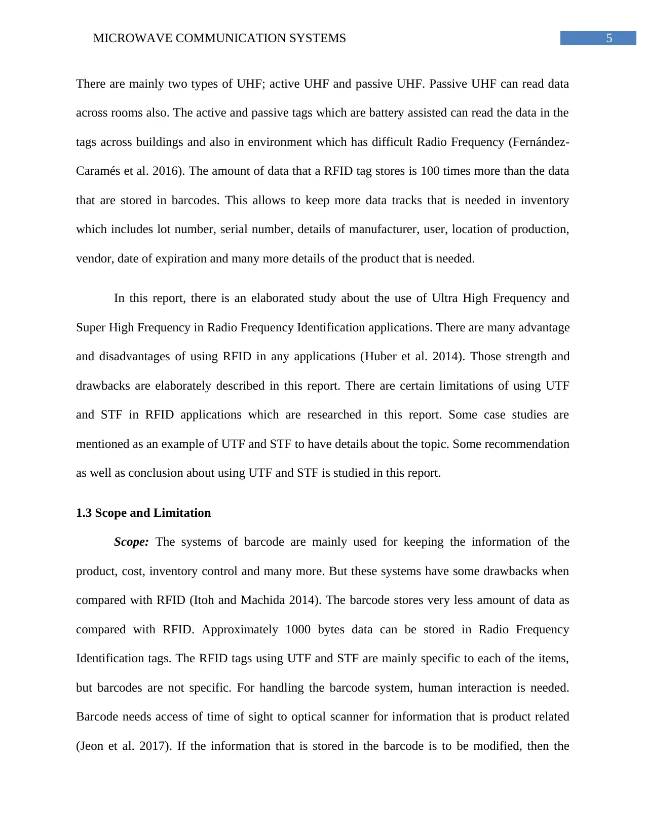
Chapter 2: Discussion
2.1 Block Diagram
Figure 1: Schematic Diagram with UTP Dual Band Antenna
(Source: Created by Author)
Figure 2: Schematic Diagram with STP Antenna Conventional Band
Chapter 2: Discussion
2.1 Block Diagram
Figure 1: Schematic Diagram with UTP Dual Band Antenna
(Source: Created by Author)
Figure 2: Schematic Diagram with STP Antenna Conventional Band
⊘ This is a preview!⊘
Do you want full access?
Subscribe today to unlock all pages.
Trusted by 1+ million students worldwide
9MICROWAVE COMMUNICATION SYSTEMS
(Source: Created by Author)
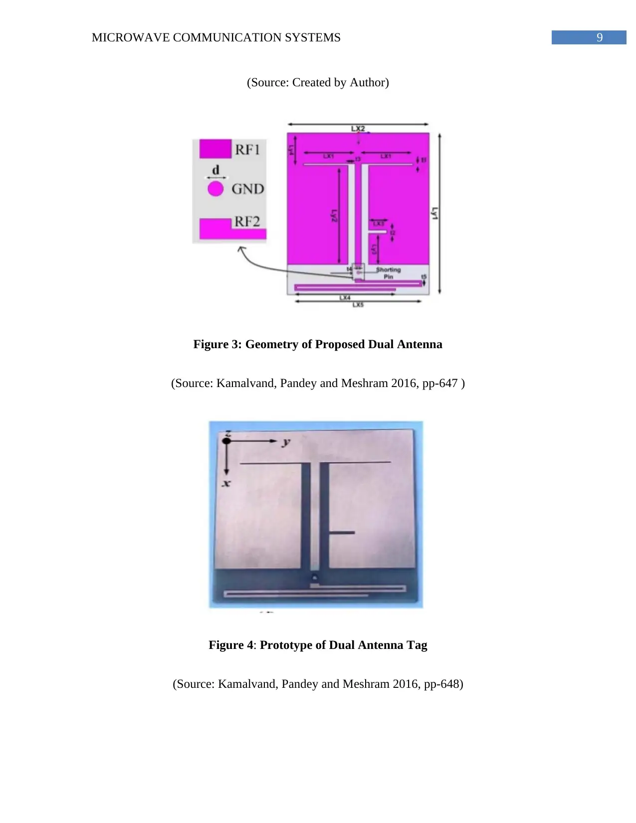
Figure 3: Geometry of Proposed Dual Antenna
(Source: Kamalvand, Pandey and Meshram 2016, pp-647 )
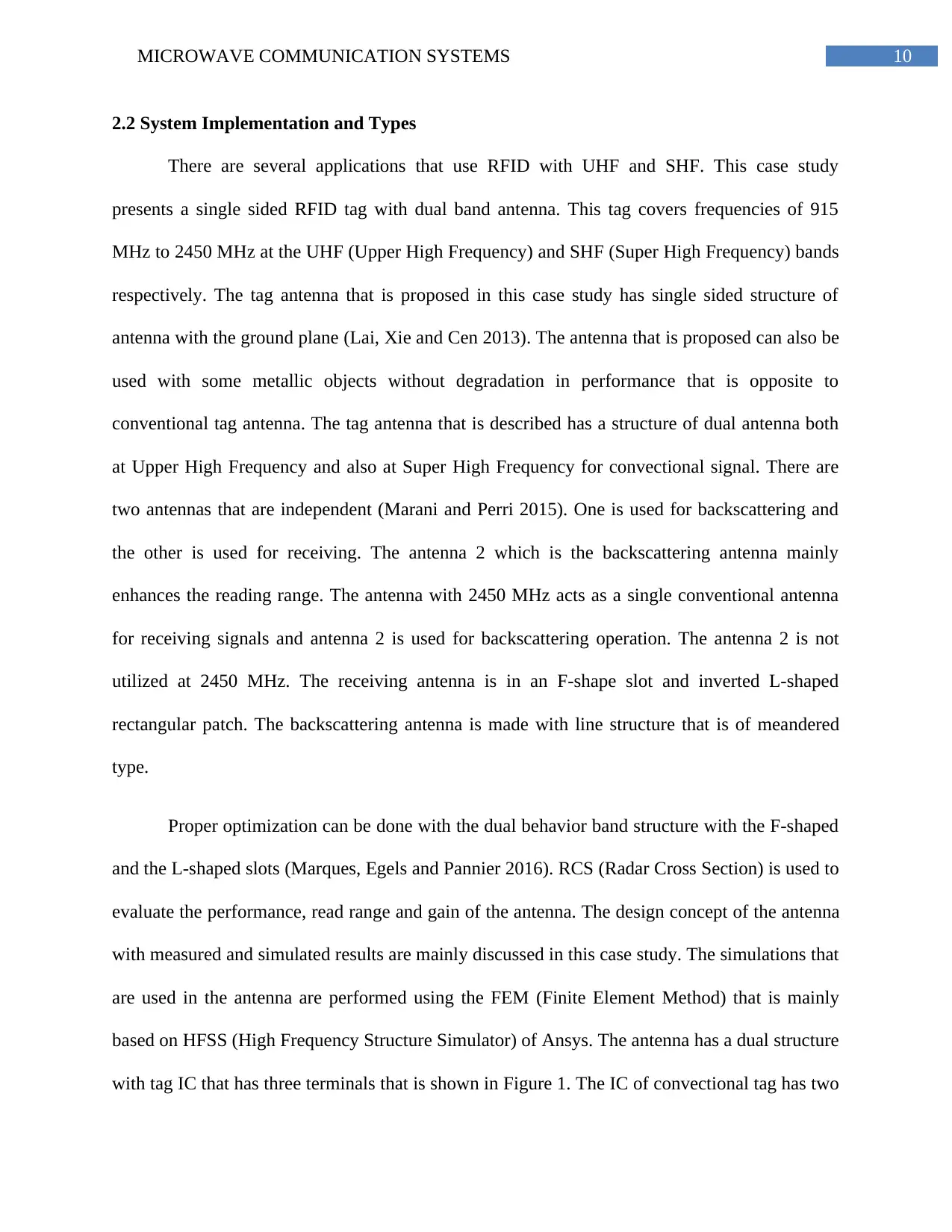
Figure 4: Prototype of Dual Antenna Tag
(Source: Kamalvand, Pandey and Meshram 2016, pp-648)
(Source: Created by Author)
Figure 3: Geometry of Proposed Dual Antenna
(Source: Kamalvand, Pandey and Meshram 2016, pp-647 )
Figure 4: Prototype of Dual Antenna Tag
(Source: Kamalvand, Pandey and Meshram 2016, pp-648)
Paraphrase This Document
Need a fresh take? Get an instant paraphrase of this document with our AI Paraphraser
10MICROWAVE COMMUNICATION SYSTEMS
2.2 System Implementation and Types
There are several applications that use RFID with UHF and SHF. This case study
presents a single sided RFID tag with dual band antenna. This tag covers frequencies of 915
MHz to 2450 MHz at the UHF (Upper High Frequency) and SHF (Super High Frequency) bands
respectively. The tag antenna that is proposed in this case study has single sided structure of
antenna with the ground plane (Lai, Xie and Cen 2013). The antenna that is proposed can also be
used with some metallic objects without degradation in performance that is opposite to
conventional tag antenna. The tag antenna that is described has a structure of dual antenna both
at Upper High Frequency and also at Super High Frequency for convectional signal. There are
two antennas that are independent (Marani and Perri 2015). One is used for backscattering and
the other is used for receiving. The antenna 2 which is the backscattering antenna mainly
enhances the reading range. The antenna with 2450 MHz acts as a single conventional antenna
for receiving signals and antenna 2 is used for backscattering operation. The antenna 2 is not
utilized at 2450 MHz. The receiving antenna is in an F-shape slot and inverted L-shaped
rectangular patch. The backscattering antenna is made with line structure that is of meandered
type.
Proper optimization can be done with the dual behavior band structure with the F-shaped
and the L-shaped slots (Marques, Egels and Pannier 2016). RCS (Radar Cross Section) is used to
evaluate the performance, read range and gain of the antenna. The design concept of the antenna
with measured and simulated results are mainly discussed in this case study. The simulations that
are used in the antenna are performed using the FEM (Finite Element Method) that is mainly
based on HFSS (High Frequency Structure Simulator) of Ansys. The antenna has a dual structure
with tag IC that has three terminals that is shown in Figure 1. The IC of convectional tag has two
11MICROWAVE COMMUNICATION SYSTEMS
terminals that have structure of single antenna shown in Figure 2. The terminals in tag of the
structure are named as common ground, RF1 and RF2. The signal terminals RF1 is used for
receiving antenna and the RF2 signal is used for backscattering antenna (Meyer, Dao and Geck
2014). Ground terminal is a common terminal that is used for connecting both terminals to other
terminals.
The prototype that is fabricated and geometry for the dual band antenna that uses UHF
and SHF and the antenna of convectional signal are illustrated in Figure 4. The antenna is
fabricated with a low cost substrate with FR4 dielectric constant 4.4 and has thickness of about
1.6 mm and loss tangent of tan d 5 0.018. The antenna of Radio Frequency Identification that is
proposed is mainly designed for tag chip of Impinj Monza Gen2 that has input impedance with
33-j112 X at 915 MHz and also 50 X at 2450 MHz. The antenna-1 which is used for receiving
signals has two back to back L-shaped slits that are inverted with loaded antenna of the dual
band (Meyer et al. 2017). After the optimization is done, the shape of antenna and slits
parameters that has SHF and UHF bands are received with 915 and 2480 MHz. The SHF band
has a tune of 2450 MHz. A slit of inverted L-shaped can be added to right side of the antenna to
make the slit F-shaped. The electrical length of the patches increases due to this and there is a
decrease of resonance frequency. The antenna-1 which is used for receiving has inverted L-
shaped slit and F-shaped slits that are loaded with rectangular patches that are evolved. The
backscattering terminal has a line structure that is meandered. Both the terminals of the antenna
are usually connected with the tag chip via a cylindrical structure. The actual size of the antenna
is mainly 70 mm x 80 mm.
Antenna-1 for receiving signal is mainly designed in a way that has input impedance is
915 MHz and 2450 MHz. This is a complex conjugate tag chip so that there is a maximum
⊘ This is a preview!⊘
Do you want full access?
Subscribe today to unlock all pages.
Trusted by 1+ million students worldwide
1 out of 24
Related Documents


Your All-in-One AI-Powered Toolkit for Academic Success.
+13062052269
info@desklib.com
Available 24*7 on WhatsApp / Email
![[object Object]](/_next/static/media/star-bottom.7253800d.svg)
Unlock your academic potential
Copyright © 2020–2026 A2Z Services. All Rights Reserved. Developed and managed by ZUCOL.