Detailed Report: Steel Structure Design for Pressure Vessel Support
VerifiedAdded on 2020/05/28
|11
|1131
|89
Report
AI Summary
This report presents a comprehensive analysis of a steel structure designed to support a pressure vessel. It begins with the provided specifications, including dimensions, material properties (S275 steel), and loading conditions. The initial design, modeled in Staad Pro, utilizes 50x50x5 mm angle sections and considers both dead and live loads, accounting for the structure's 5-degree inclination. The analysis reveals a failure in the slenderness ratio, leading to a collapse scenario. The report then proposes a redesign using 75x75x5 mm angle sections, successfully addressing the slenderness ratio issue and ensuring structural integrity. The report concludes with recommendations for safe lifting and mechanical handling of the vessel, emphasizing crane operation and deflection monitoring. The steel take-off calculations are also included, which provides the total steel material needed for the structure.
STEEL STRUCTURE DESIGN REPORT
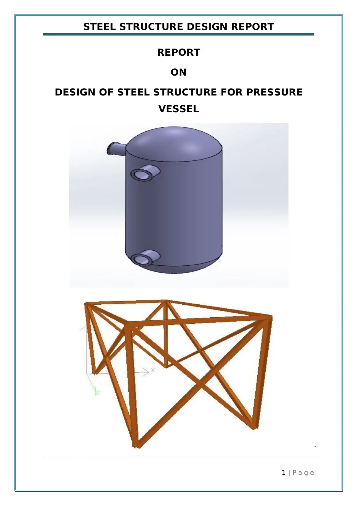
REPORT
ON
DESIGN OF STEEL STRUCTURE FOR PRESSURE
VESSEL
1 | P a g e
REPORT
ON
DESIGN OF STEEL STRUCTURE FOR PRESSURE
VESSEL
1 | P a g e
Paraphrase This Document
Need a fresh take? Get an instant paraphrase of this document with our AI Paraphraser
STEEL STRUCTURE DESIGN REPORT
PRESENT CONDITIONS PROVIDED
Given Pressure Vessel details
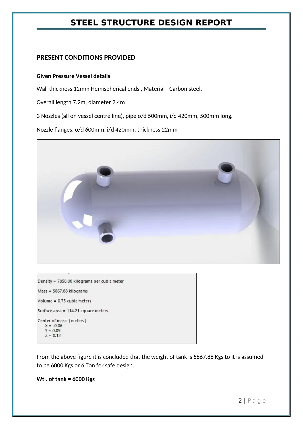
Wall thickness 12mm Hemispherical ends , Material - Carbon steel.
Overall length 7.2m, diameter 2.4m
3 Nozzles (all on vessel centre line), pipe o/d 500mm, i/d 420mm, 500mm long.
Nozzle flanges, o/d 600mm, i/d 420mm, thickness 22mm
From the above figure it is concluded that the weight of tank is 5867.88 Kgs to it is assumed
to be 6000 Kgs or 6 Ton for safe design.
Wt . of tank = 6000 Kgs
2 | P a g e
STEEL STRUCTURE DESIGN REPORT
As volume of tank is 0.75 m^3 , so consider water filled in it completely. So weight of water
is :-
mass = density * volume
mass = 1000 * 0.75
Mass of water present in the vessel = 750 Kgs
Stillage/Structure details :-
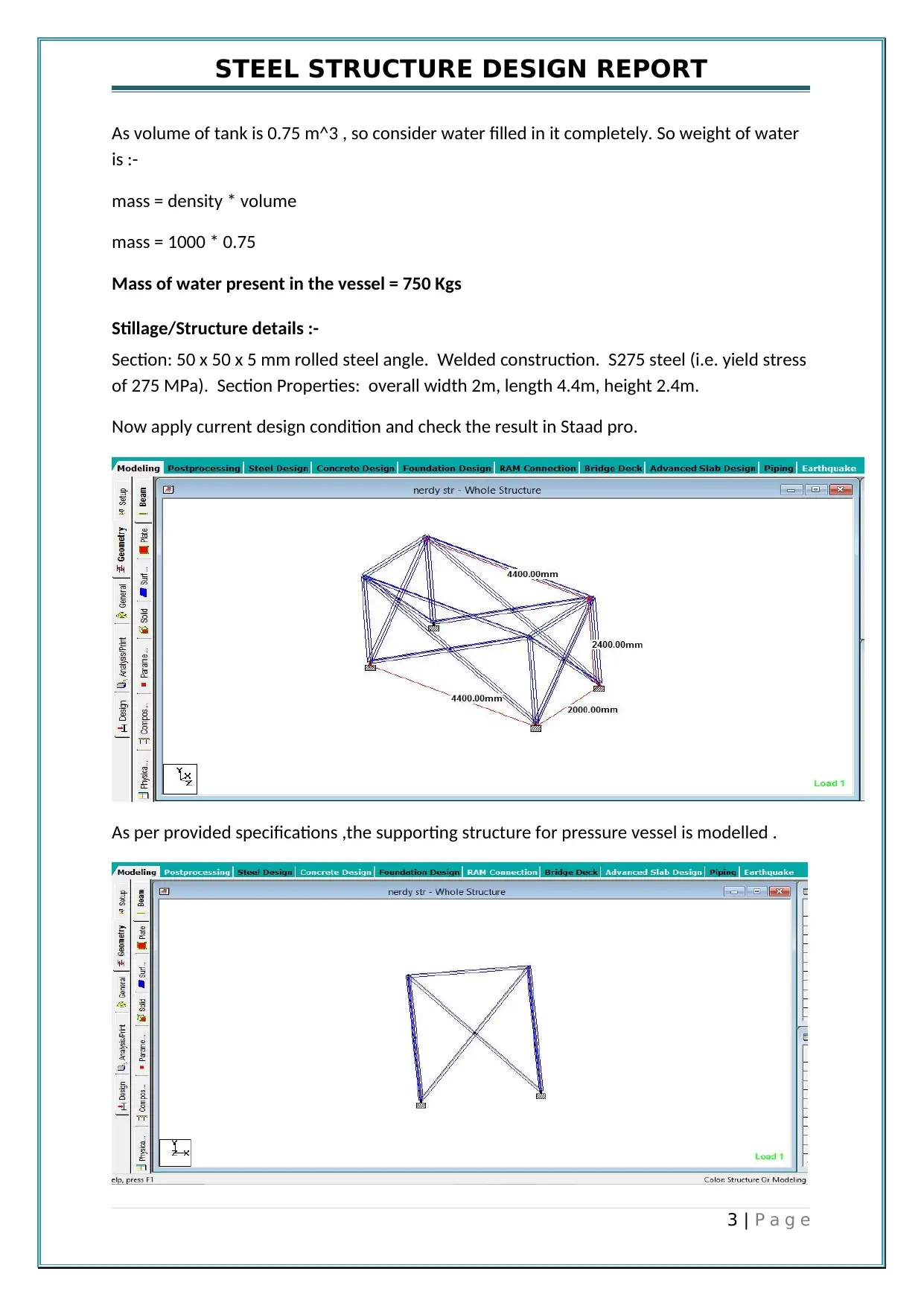
Section: 50 x 50 x 5 mm rolled steel angle. Welded construction. S275 steel (i.e. yield stress
of 275 MPa). Section Properties: overall width 2m, length 4.4m, height 2.4m.
Now apply current design condition and check the result in Staad pro.
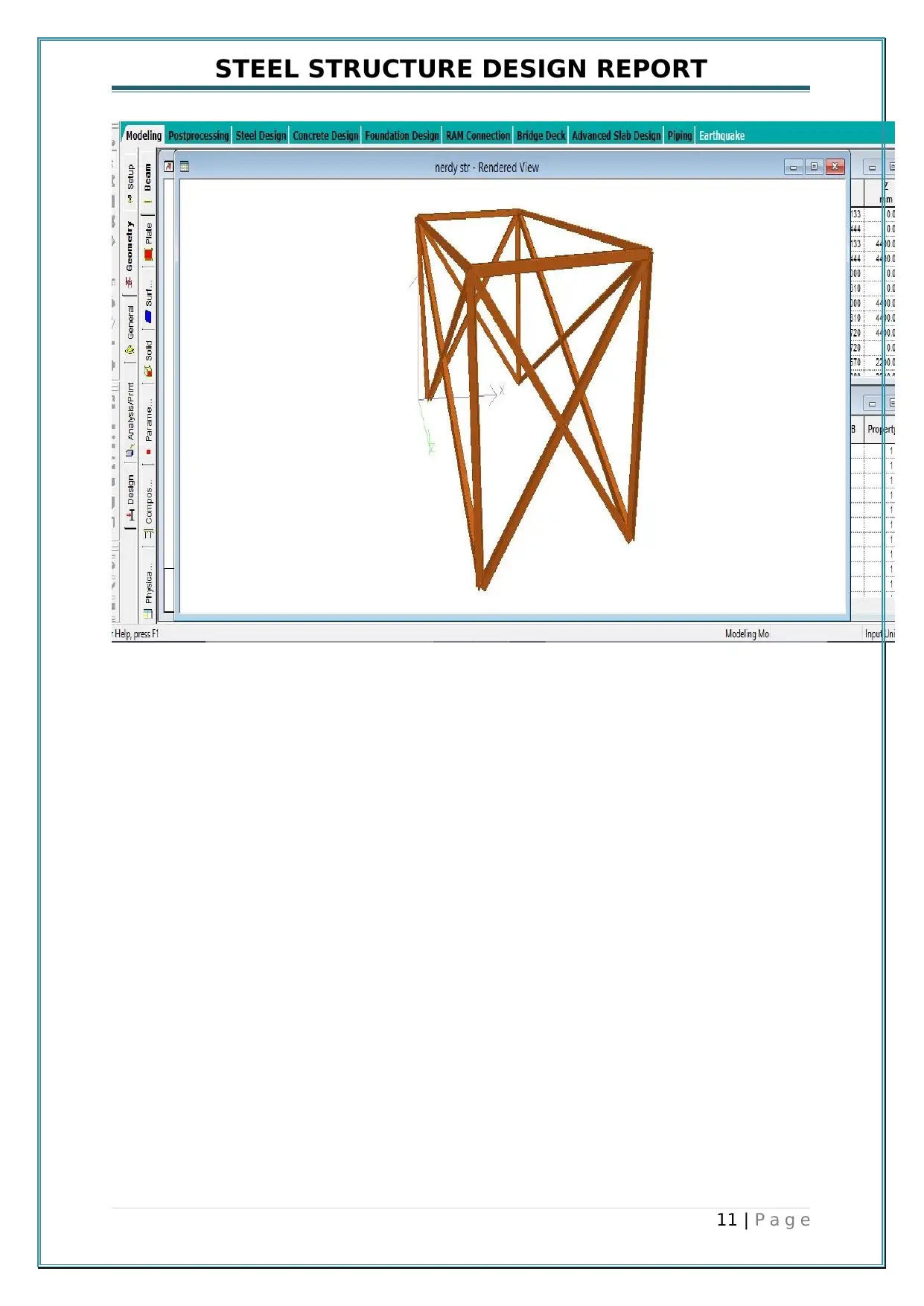
As per provided specifications ,the supporting structure for pressure vessel is modelled .
3 | P a g e
⊘ This is a preview!⊘
Do you want full access?
Subscribe today to unlock all pages.

Trusted by 1+ million students worldwide
STEEL STRUCTURE DESIGN REPORT
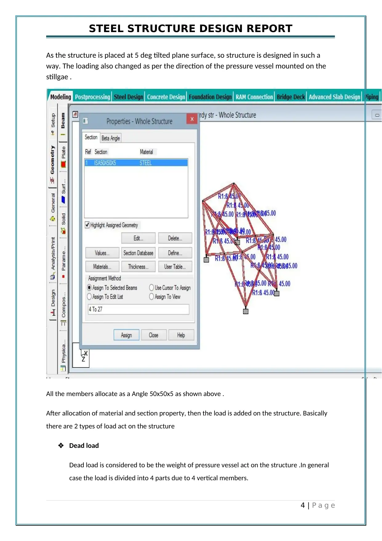
As the structure is placed at 5 deg tilted plane surface, so structure is designed in such a
way. The loading also changed as per the direction of the pressure vessel mounted on the
stillgae .
All the members allocate as a Angle 50x50x5 as shown above .
After allocation of material and section property, then the load is added on the structure. Basically
there are 2 types of load act on the structure
Dead load
Dead load is considered to be the weight of pressure vessel act on the structure .In general
case the load is divided into 4 parts due to 4 vertical members.
4 | P a g e
Paraphrase This Document
Need a fresh take? Get an instant paraphrase of this document with our AI Paraphraser
STEEL STRUCTURE DESIGN REPORT
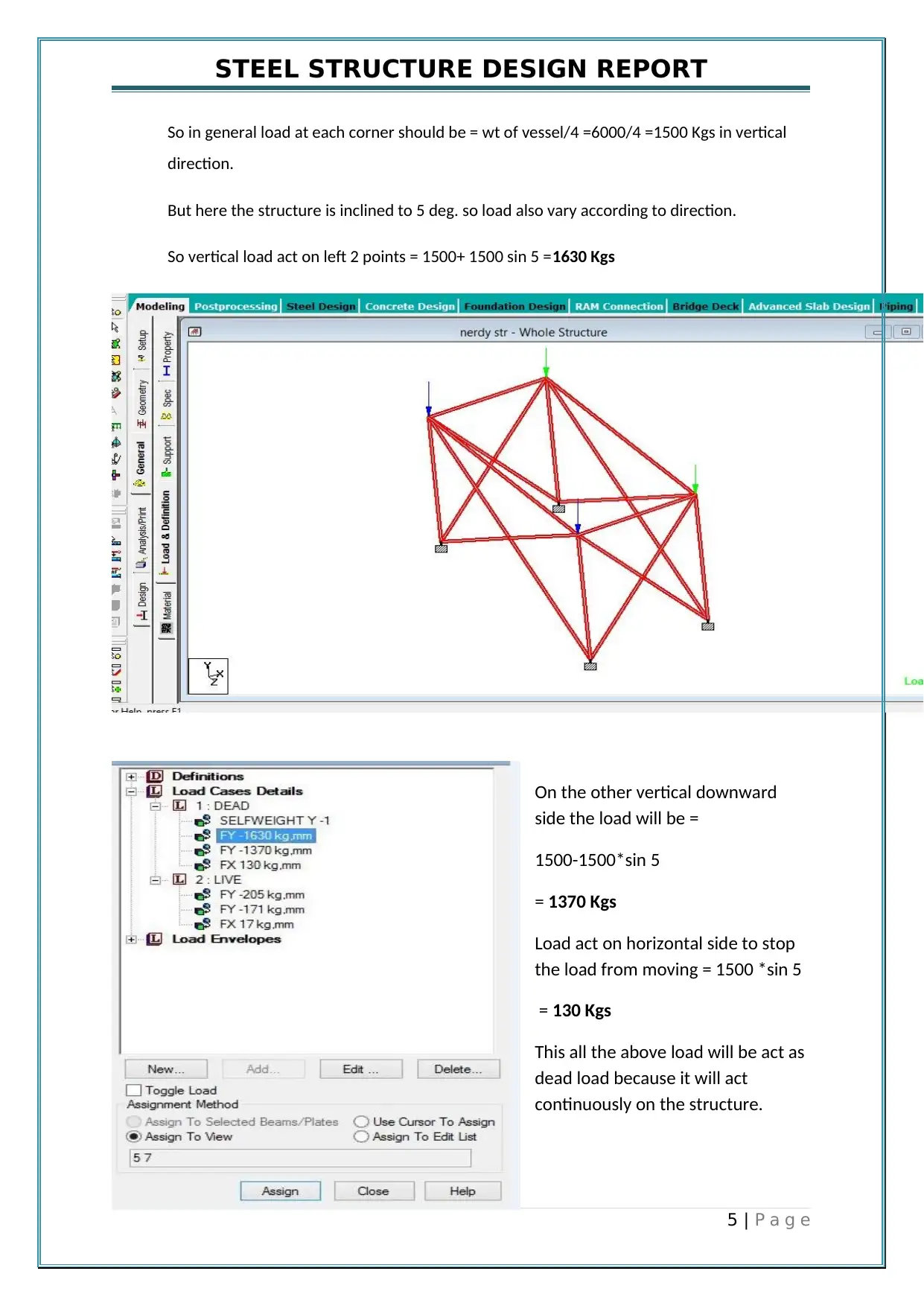
So in general load at each corner should be = wt of vessel/4 =6000/4 =1500 Kgs in vertical
direction.
But here the structure is inclined to 5 deg. so load also vary according to direction.
So vertical load act on left 2 points = 1500+ 1500 sin 5 =1630 Kgs
On the other vertical downward
side the load will be =
1500-1500*sin 5
= 1370 Kgs
Load act on horizontal side to stop
the load from moving = 1500 *sin 5
= 130 Kgs
This all the above load will be act as
dead load because it will act
continuously on the structure.
5 | P a g e
STEEL STRUCTURE DESIGN REPORT
Live Load
Live load is a load which act on the structure while vessel is completely filled and in
operation.
Live load will be total weight of water in vessel =750 Kgs
So in general load at each corner should be = wt of water in vessel/4 =750/4 =187.5 Kgs in
vertical direction.
But here the structure is inclined to 5 deg. so load also vary according to direction.
So vertical load act on left 2 points =187.5+ 187.5 *sin 5 =205 Kgs (aproxx)
On the other vertical downward side the load will be =187.5- 187.5 sin 5
= 171 Kgs
Load act on horizontal side to stop the load from moving = 187.5 *sin 5
= 17 Kgs
This all the above load will be act as dead load because it will act continuously on the
structure.
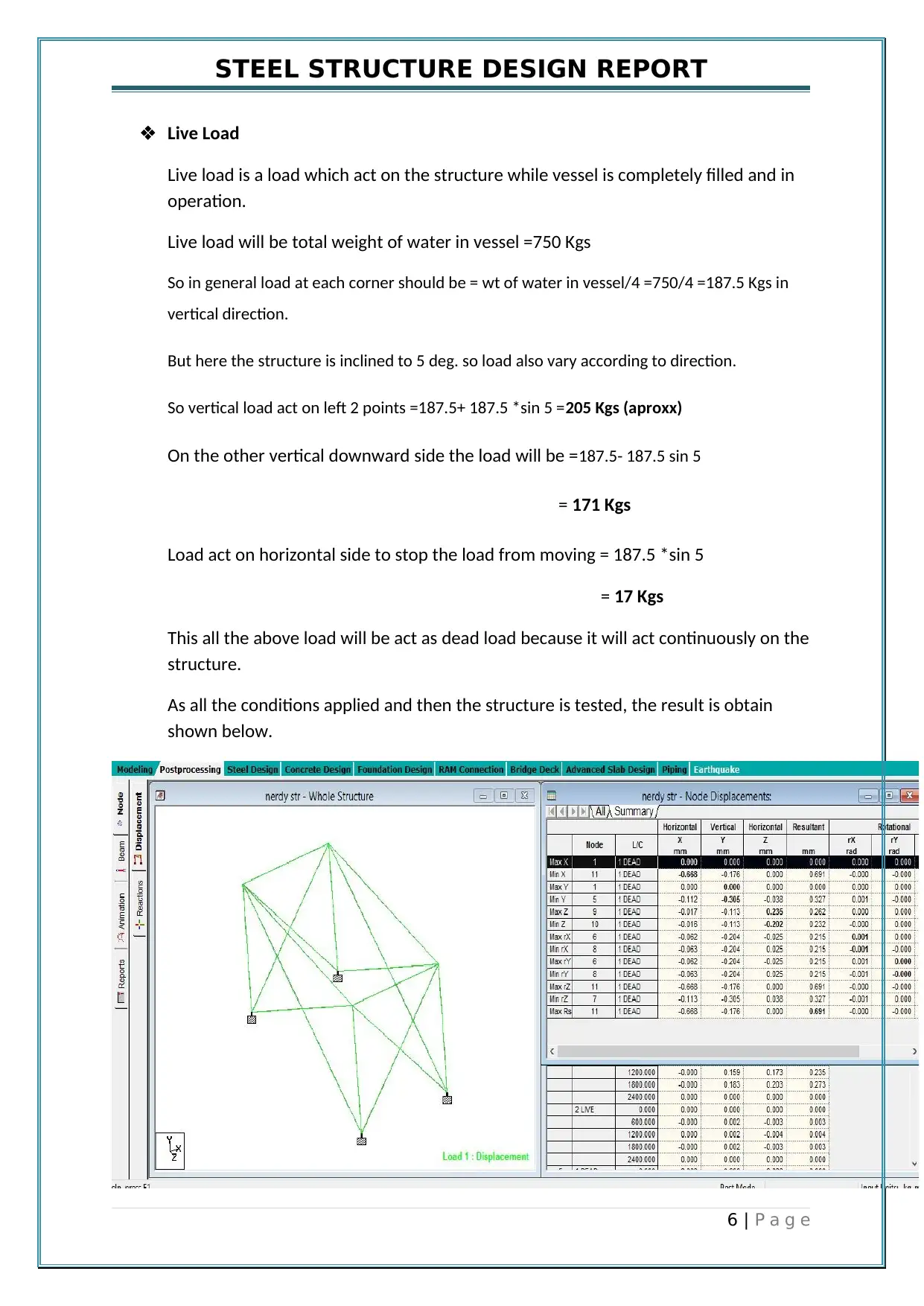
As all the conditions applied and then the structure is tested, the result is obtain
shown below.
6 | P a g e
⊘ This is a preview!⊘
Do you want full access?
Subscribe today to unlock all pages.

Trusted by 1+ million students worldwide
STEEL STRUCTURE DESIGN REPORT
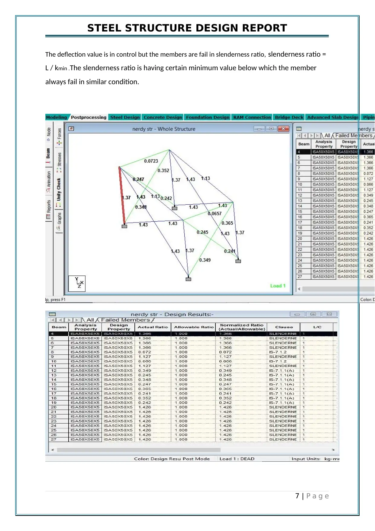
The deflection value is in control but the members are fail in slenderness ratio, slenderness ratio =
L / kmin .The slenderness ratio is having certain minimum value below which the member
always fail in similar condition.
7 | P a g e
The deflection value is in control but the members are fail in slenderness ratio, slenderness ratio =
L / kmin .The slenderness ratio is having certain minimum value below which the member
always fail in similar condition.
7 | P a g e
Paraphrase This Document
Need a fresh take? Get an instant paraphrase of this document with our AI Paraphraser
STEEL STRUCTURE DESIGN REPORT
Question / Answers
1. Why did the leg collapse? What effects or details did the designer ignore?
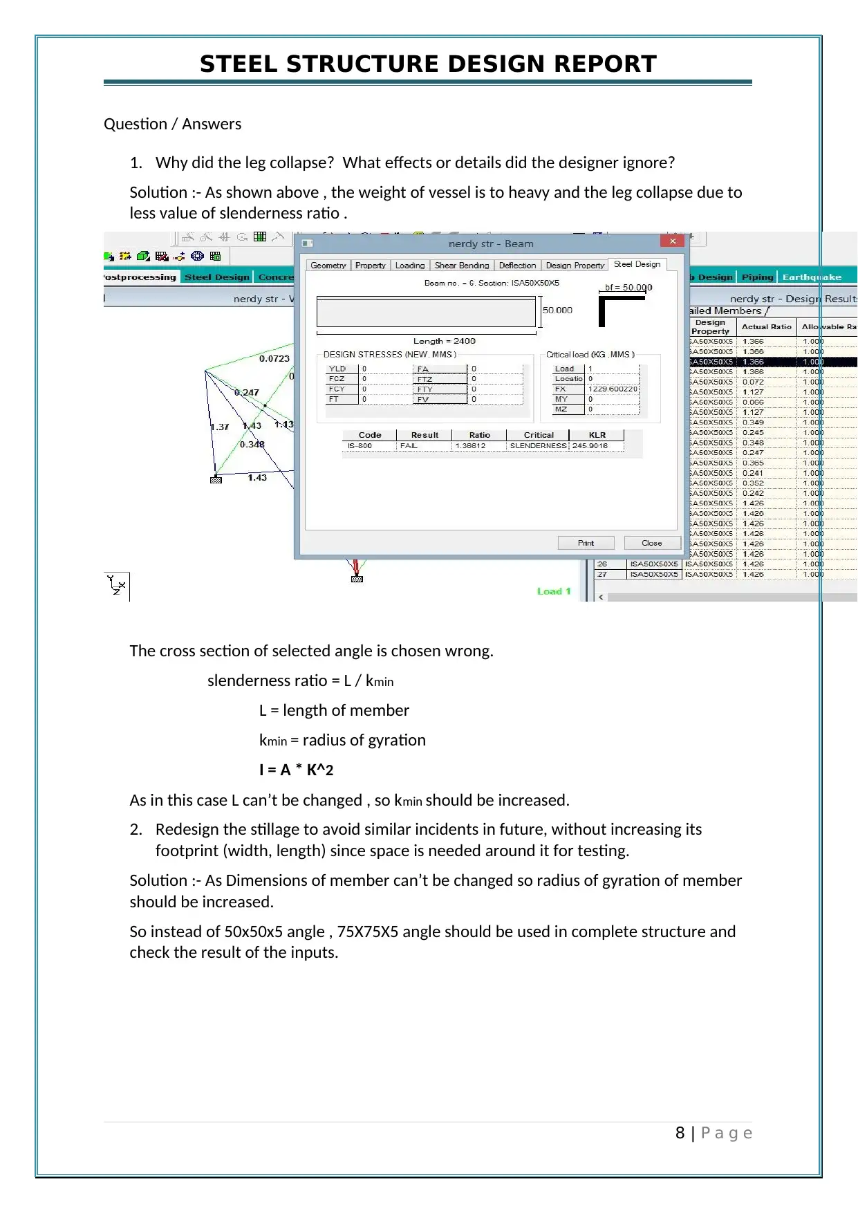
Solution :- As shown above , the weight of vessel is to heavy and the leg collapse due to
less value of slenderness ratio .
The cross section of selected angle is chosen wrong.
slenderness ratio = L / kmin
L = length of member
kmin = radius of gyration
I = A * K^2
As in this case L can’t be changed , so kmin should be increased.
2. Redesign the stillage to avoid similar incidents in future, without increasing its
footprint (width, length) since space is needed around it for testing.
Solution :- As Dimensions of member can’t be changed so radius of gyration of member
should be increased.
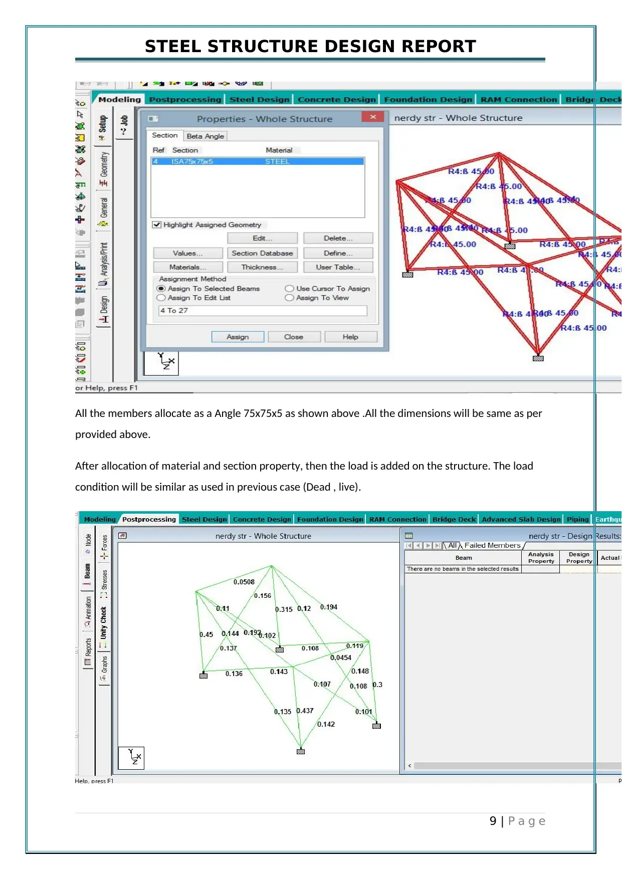
So instead of 50x50x5 angle , 75X75X5 angle should be used in complete structure and
check the result of the inputs.
8 | P a g e
STEEL STRUCTURE DESIGN REPORT
All the members allocate as a Angle 75x75x5 as shown above .All the dimensions will be same as per
provided above.
After allocation of material and section property, then the load is added on the structure. The load
condition will be similar as used in previous case (Dead , live).
9 | P a g e
All the members allocate as a Angle 75x75x5 as shown above .All the dimensions will be same as per
provided above.
After allocation of material and section property, then the load is added on the structure. The load
condition will be similar as used in previous case (Dead , live).
9 | P a g e
⊘ This is a preview!⊘
Do you want full access?
Subscribe today to unlock all pages.

Trusted by 1+ million students worldwide
STEEL STRUCTURE DESIGN REPORT
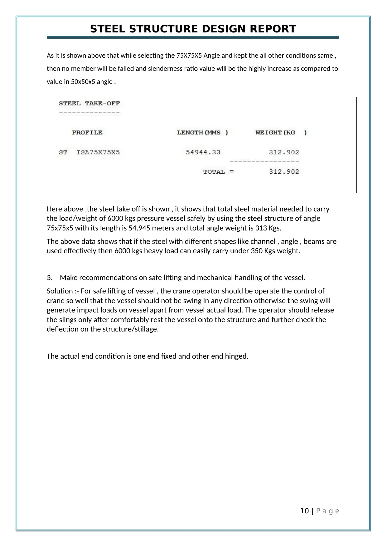
As it is shown above that while selecting the 75X75X5 Angle and kept the all other conditions same ,
then no member will be failed and slenderness ratio value will be the highly increase as compared to
value in 50x50x5 angle .
Here above ,the steel take off is shown , it shows that total steel material needed to carry
the load/weight of 6000 kgs pressure vessel safely by using the steel structure of angle
75x75x5 with its length is 54.945 meters and total angle weight is 313 Kgs.
The above data shows that if the steel with different shapes like channel , angle , beams are
used effectively then 6000 kgs heavy load can easily carry under 350 Kgs weight.
3. Make recommendations on safe lifting and mechanical handling of the vessel.
Solution :- For safe lifting of vessel , the crane operator should be operate the control of
crane so well that the vessel should not be swing in any direction otherwise the swing will
generate impact loads on vessel apart from vessel actual load. The operator should release
the slings only after comfortably rest the vessel onto the structure and further check the
deflection on the structure/stillage.
The actual end condition is one end fixed and other end hinged.
10 | P a g e
Paraphrase This Document
Need a fresh take? Get an instant paraphrase of this document with our AI Paraphraser
STEEL STRUCTURE DESIGN REPORT
11 | P a g e
11 | P a g e
1 out of 11
Your All-in-One AI-Powered Toolkit for Academic Success.
+13062052269
info@desklib.com
Available 24*7 on WhatsApp / Email
![[object Object]](/_next/static/media/star-bottom.7253800d.svg)
Unlock your academic potential
Copyright © 2020–2025 A2Z Services. All Rights Reserved. Developed and managed by ZUCOL.