Residential Construction: Concrete Footings, Hydraulic Services, Load Bearing Walls, Scaffold Systems
VerifiedAdded on 2023/06/13
|21
|4697
|236
AI Summary
This assignment discusses the elements of residential construction, including concrete footings, hydraulic services, load bearing walls, and scaffold systems. It covers relevant standards, assembly sequence, materials, and labor required for each element. The assignment is for BLAR11050 Term 1 2018 Assignment 2.
Contribute Materials
Your contribution can guide someone’s learning journey. Share your
documents today.
Residential Construction 1
Residential Construction
Assignment 2
BLAR11050
Term 1 2018
Due Date: May 4 2018
Weighting: 30%
Residential Construction
Assignment 2
BLAR11050
Term 1 2018
Due Date: May 4 2018
Weighting: 30%
Secure Best Marks with AI Grader
Need help grading? Try our AI Grader for instant feedback on your assignments.
Residential Construction 2
Table of Contents
Introduction...........................................................................................................................................2
Question 1:............................................................................................................................................3
Question 2:............................................................................................................................................9
Question 3:..........................................................................................................................................14
Conclusion:..........................................................................................................................................17
References...........................................................................................................................................18
Residential Construction 3
Introduction
A class 1a type of development is defined as a single dwelling unit which is detached from
other buildings, or a unitary house which is detached from others by use of a fire resistant
wall. They can either be villa units, town houses, terrace houses or row houses.
The houses are constituted of several structural members from footings, foundations, columns
beams and slab decks. In this assignment, one such project was identified and the elements
discussed herein are concrete footings, hydraulic services, doors and windows and load
bearing walls.
Residential Construction 4
Question 1:
Concrete footings
Concrete footings are structural elements that are used to transfer loads from a building to the
foundation. There are different types of footings such as spread footing, strip footing (also
called wall footing), and combined footing.
Spread footing is a footing that has a column in the middle of the footing. The force acting
downward from the load bearing column is spread on the soil by the spread footing. The
bottom of the spread footing is in tension. The tension arises from the bending moment due to
the downward force caused by the column and the earth resistance. Engineers usually design
the spread footings according to the load computations that the footings are expected to carry
from the supporting column CITATION DeL14 \l 1033 (De Larrard, 2014). The design results give
the reinforcement that will be used in the construction of the footing. Since concrete is weak
in tension, the design of footings will always yield a reinforcement of the bottom part of the
spread footing to support the columns and dissipate loads to the soil.
Strip footing are footings that have a continuous wall above them. The footings are utilized to
distribute the forces acting through the wall to the ground CITATION Caj14 \l 1033 (Cajka, et al.,
2014).
Combined footings are concrete spread footings that are under multiple columns. The layout
of this footing may vary widely depending on the locations of the columns and the loads they
carry. The design of combined footings yields reinforcement on both the bottom and top parts
of the footing because of the effect of the column forces on the footing. A bending moment
diagram is used to indicate the critical areas for reinforcement CITATION Jan13 \l 1033
(Janulíková & Marie , 2013).
Relevant standards
AS 2870 – 1996 has the codes that govern the construction of residential slabs and footings.
Assembly sequence
The placing of concrete is an activity that has to be preceded by some others. Excavation of
the foundation trench needs to have been done using a Backhoe. Depending on the elevation
of the building pad elevation, it may be necessary to have formwork for the footing. The
reinforcement bar to be used is placed such that there is a clearance from the earth. This is
Secure Best Marks with AI Grader
Need help grading? Try our AI Grader for instant feedback on your assignments.
Residential Construction 5
done by having spacer blocks between the reinforcement and the earth. The rebar is also fixed
in position by tying them using s particular gauge of rods. This is done to ensure that the
rebar do not move while the concrete is being placed. The rebar needs to be at specific
locations before, during and after placing of concrete CITATION Gha14 \l 1033 (Ghali, et al.,
2014).
The prevailing project circumstances may make the concrete placing procedure to vary. A
ready mix concrete truck can be used to place the concrete by running along the footing
trench and chute concrete directly into the footings. Wheelbarrows can also be used to carry
concrete from the truck to the footing. Concrete pumps could also be used to transport
concrete to the foundationsCITATION AlA19 \l 1033 (Al-Ansari, 2017).
Hydraulic services
The water corporation, the National Construction Corporation (NCC) and the Department of
Fire and Emergency services (DFES) all outline the scope of hydraulic works to be done in
construction projects. These works are; sanitary plumbing, property sewer, supply of water
and fire services and drainage of stormwater.
Before any works can commence, all permits are required to be submitted to the relevant
authority. The key considerations to be looked into are the water quality to be used, health
and safety of the building and its users, availability of material, ease of maintenance and the
design life of the material CITATION Kar18 \l 1033 (Karcher, et al., Mar 2018).
The requirements for a class 1A type of structure for hydraulic services are as follows; the
mains water must have a filtering and conditioning unit. The use of water is monitored by the
use of an installed meter. Flow restrictions are installed in taps in addition to having leak
detection systems. Electric point-of-use hot water are normally installed to the specification
of a building. Generally chrome plated valves, or high performance mixing valves are
recommended for hot water units. Internal wet rooms are usually installed with floor wastes
or gullies and bucket traps. The floor is usually graded to the specifications of the approved
design. It is not necessary to install puddle flanges on the ground level, but all other floor
areas including balconies are needed CITATION WuJ14 \l 1033 (Wu, et al., 2014).
According to Australian standards, box gutters are required to have the same area as the
downpipes.
Plumbing fixtures or tapware are usually installed after completion of tiling works using a
specified sealant. Pans and cisterns, urinals, hand basins, taps and showers are fitted to the
Residential Construction 6
requirement of the specification documents.
A contractor is required to avail samples of the above named units, which he is intending to
supply, for client approval prior to eventual supply and fixing of the same.
Relevant standards
The following Australian Standards are used for the design of hydraulic services in Class 1a
constructions.
AS/NZS 3500.1 – Plumbing and drainage; water services
AS/NZS 3500.2 – Plumbing and drainage; sanitary plumbing and drainage
AS/NZS 3500.3 – Plumbing and drainage; stormwater drainage
AS/NZS 3500.4 – Plumbing and drainage; heated water services
AS/NZS 5601 – Gas Installations
AS 1345 – Identification of the contents of pipes, conduits and ducts.
AS/NZS 1546.1 – On-site waste management treatment units, Septic tanks
Assembly sequence
Sanitary plumbing fixtures include; wastewater connections and fittings, and all trims and
traps. Their installation must comply with AS/NZS 3500.2 – Plumbing and drainage; sanitary
plumbing and drainage.
Just before installation, all components are visually inspected for likely contamination and
damage. The fittings are then lubricated at the threads before assembly. The installations are
initially done hand – tight. This is because the installation must be checked for tubing of
mating hose assembly CITATION Bes15 \l 1033 (Best, et al., 2015). Proper alignment of fittings
can also be achieved through this.
Tightening of the fixtures is carried out by the following methods
Specified torque method
Flats from finger tight method
Materials required
Hydraulic services are usually made of aluminium, brass, cast iron and stainless steel
material. The range of materials produced are;
Hydraulic pipes
Hydraulic tubes
Residential Construction 7
Hydraulic hose
Fittings such as compression fittings, crimps, end fittings, flanges, push to connect
and threaded fittings
Labour required
The labour required for installation of hydraulic services is generally a qualified fitter. The
industry practice is to have a fitter with a minimum of 4 star WELS rating.
Load bearing walls
Load bearing walls are walls that are used to carry and distribute loads from the roof of a
structure and upper floors to the footing. The gauging of load bearing walls to the required
thickness to carry the designed loads above them is dependent on the number of floors and eh
building type CITATION Nie16 \l 1033 (Nielsen & Linh , 2016).
Removal or damage of a load bearing wall could lead to sagging of floors, cracking of
interior walls or even collapse of the structure. Australian Standards requires that any
removal or modification that is done on load bearing walls should be supported with steel
beams. The use of a laminated veneer timber beam is possible for the same purpose. The
expected weight the beam is to carry determined the eventual size of the beam. These weights
are to be computed before demolition of the existing load bearing wall. Load bearing walls do
not however perform well in earthquakes due to their weight CITATION Ber13 \l 1033 (Berggren
& Wall, 2013).
Relevant standards
The relevant standard for design of load bearing walls is AS 3700 which gives a guide on
masonry structures.
Assembly sequence
The installation of load bearing walls is effected through platform framing (a light
construction method). In this method, the load bearing walls each sit on a wall sill plate. The
wall is usually mated to the lowest base plate CITATION Pileb \l 1033 (Pilz, et al., 2014 Feb). The
sills are also anchored to the masonry or concrete foundations be use of bolts. The top of the
wall has ceiling plate which is located just below the platform of the next floor. The bottom
attachment of the wall is the floor or base plate. This plate acts as an attachment point for
Paraphrase This Document
Need a fresh take? Get an instant paraphrase of this document with our AI Paraphraser
Residential Construction 8
wall studs. The combined used of these plates make the wall construction to be possible while
lying on its side. This method gives room for nailing of the plates using studs on the end
CITATION Len13 \l 1033 (Lenczner, 2013). This finished wall which is now lying on the ground
can thus be raised vertically onto the wall sills. This technique of erection is known to
produce stronger walls and also lessen the period of construction. This technique of
construction is termed as the tilt – up method CITATION Ozb13 \l 1033 (Ozbakkaloglu, et al.,
2013).
Other methods for the construction of load bearing walls are;
Cross wall – this uses precisely located prefabricated sections used to suit swift
adaptable buildings
Insulating concrete formwork (ICF) – use of insulating panels as formwork for in-
situ concreting. The panels are left in place to act as insulation after concreting had
been done.
This joint blockwork – the mortar joints are 2 - 3mm on concrete blocks that are
autoclaved and aerated.
Twin wall construction – this is a hybrid construction technique that seeks to
combine the benefits of in-situ concreting and prefabricated construction.
Tunnel form – this is a construction technique that involves the concreting of walls
and slabs in one operation.
Materials required
The list of materials required for masonry construction are; Cement, Sand, Gravel, Formwork
for in-situ concreting and Pre-cast moulds for blocks.
Labour required
The labour requirement for the construction of load bearing walls is masons.
External windows and doors
The following items are supposed to be considered during the purchase and installation of
windows and doors,
Whether the window is at the corner or not
The classification of exposure
The window rating
The design wind pressure
Windows and doors are designed to a particular wind load depending on existing site
Residential Construction 9
conditions. These loads determine the type of windows or doors that can be used on a
structure since they have a direct impact on the ultimate and serviceability limit states of a
structure CITATION Zha13 \l 1033 (Zhang & Khoshnevis, 2013). A testing procedure is usually
carried out to ensure compliance to the Building Code of Australia (BCA). The tests that are
normally carried out are;
Structural tests
Operating force test
Air filtration test
Water penetration test
Ultimate strength test
The fixing of external doors and windows should ensure that the following are adhered to;
Thermal comfort in accordance to the energy efficiency of the building.
Bush fire attack level – the falling of a building in areas prone to bush fires impacts
on the type of windows and doors to be used in the area.
Relevant standards
The codes that govern the installation of windows and doors are;
AS 2046 – Windows and external glazed doors in buildings
AS 1288 – selection and installation of windows and doors
AS 4055 and AS 1170 – Wind speed and classes for computation of wind loads
Residential Construction 10
Question 2:
A. Types of scaffold systems
A scaffold can be defined as a provisional structure which is utilized in the provision of a working
platform for construction workers. It also provides support to the original structure CITATION Rei14 \l
1033 (Reiser & Tabak, 2014). Scaffolds differ according to the type of construction work there is to
do. These are;
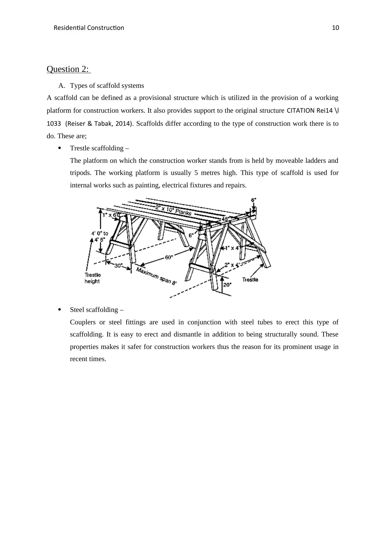
Trestle scaffolding –
The platform on which the construction worker stands from is held by moveable ladders and
tripods. The working platform is usually 5 metres high. This type of scaffold is used for
internal works such as painting, electrical fixtures and repairs.
Steel scaffolding –
Couplers or steel fittings are used in conjunction with steel tubes to erect this type of
scaffolding. It is easy to erect and dismantle in addition to being structurally sound. These
properties makes it safer for construction workers thus the reason for its prominent usage in
recent times.
Question 2:
A. Types of scaffold systems
A scaffold can be defined as a provisional structure which is utilized in the provision of a working
platform for construction workers. It also provides support to the original structure CITATION Rei14 \l
1033 (Reiser & Tabak, 2014). Scaffolds differ according to the type of construction work there is to
do. These are;
Trestle scaffolding –
The platform on which the construction worker stands from is held by moveable ladders and
tripods. The working platform is usually 5 metres high. This type of scaffold is used for
internal works such as painting, electrical fixtures and repairs.
Steel scaffolding –
Couplers or steel fittings are used in conjunction with steel tubes to erect this type of
scaffolding. It is easy to erect and dismantle in addition to being structurally sound. These
properties makes it safer for construction workers thus the reason for its prominent usage in
recent times.
Secure Best Marks with AI Grader
Need help grading? Try our AI Grader for instant feedback on your assignments.
Residential Construction 11
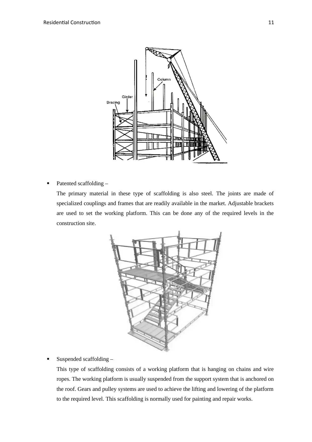
Patented scaffolding –
The primary material in these type of scaffolding is also steel. The joints are made of
specialized couplings and frames that are readily available in the market. Adjustable brackets
are used to set the working platform. This can be done any of the required levels in the
construction site.
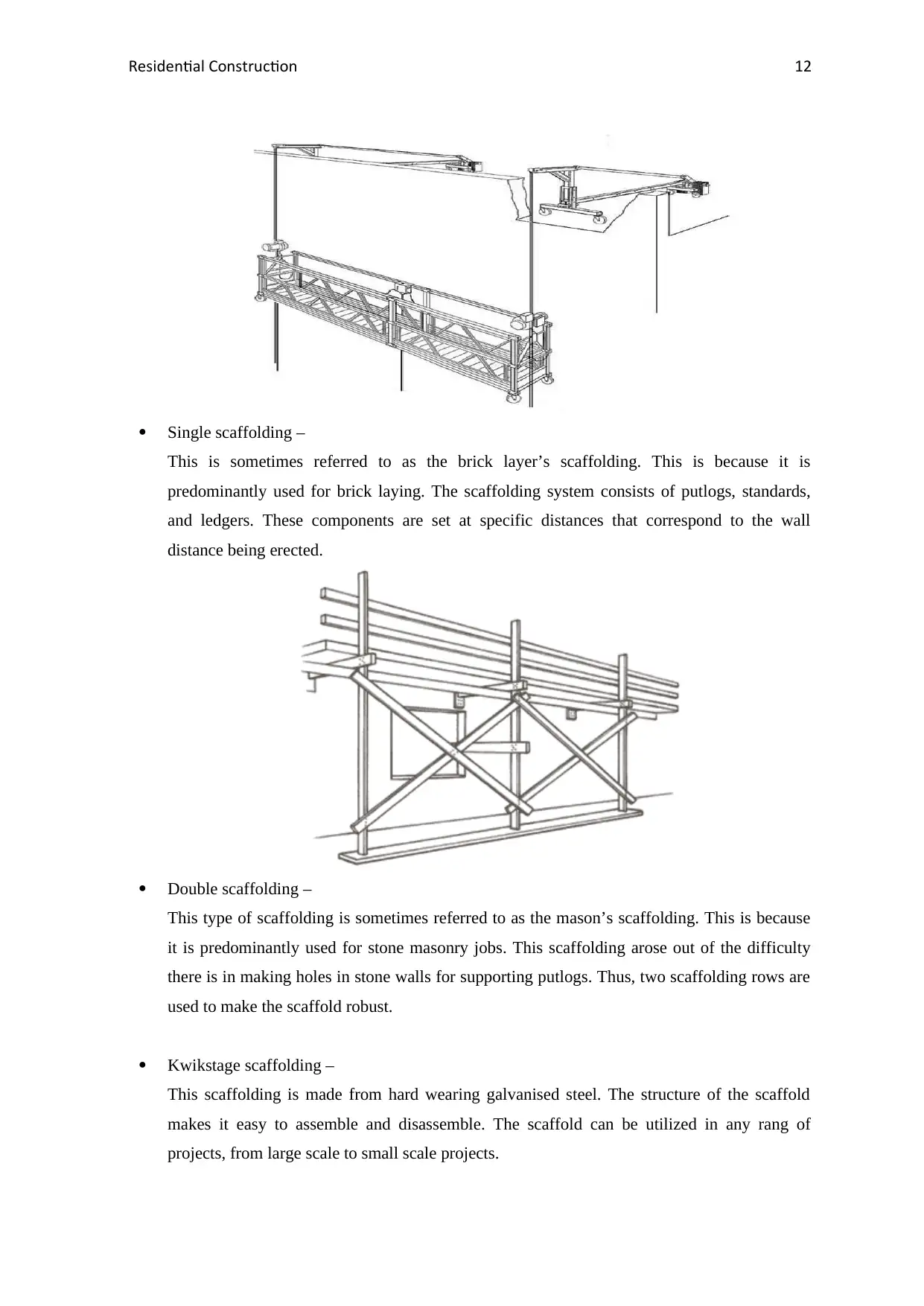
Suspended scaffolding –
This type of scaffolding consists of a working platform that is hanging on chains and wire
ropes. The working platform is usually suspended from the support system that is anchored on
the roof. Gears and pulley systems are used to achieve the lifting and lowering of the platform
to the required level. This scaffolding is normally used for painting and repair works.
Patented scaffolding –
The primary material in these type of scaffolding is also steel. The joints are made of
specialized couplings and frames that are readily available in the market. Adjustable brackets
are used to set the working platform. This can be done any of the required levels in the
construction site.
Suspended scaffolding –
This type of scaffolding consists of a working platform that is hanging on chains and wire
ropes. The working platform is usually suspended from the support system that is anchored on
the roof. Gears and pulley systems are used to achieve the lifting and lowering of the platform
to the required level. This scaffolding is normally used for painting and repair works.
Residential Construction 12
Single scaffolding –
This is sometimes referred to as the brick layer’s scaffolding. This is because it is
predominantly used for brick laying. The scaffolding system consists of putlogs, standards,
and ledgers. These components are set at specific distances that correspond to the wall
distance being erected.
Double scaffolding –
This type of scaffolding is sometimes referred to as the mason’s scaffolding. This is because
it is predominantly used for stone masonry jobs. This scaffolding arose out of the difficulty
there is in making holes in stone walls for supporting putlogs. Thus, two scaffolding rows are
used to make the scaffold robust.
Kwikstage scaffolding –
This scaffolding is made from hard wearing galvanised steel. The structure of the scaffold
makes it easy to assemble and disassemble. The scaffold can be utilized in any rang of
projects, from large scale to small scale projects.
Residential Construction 13
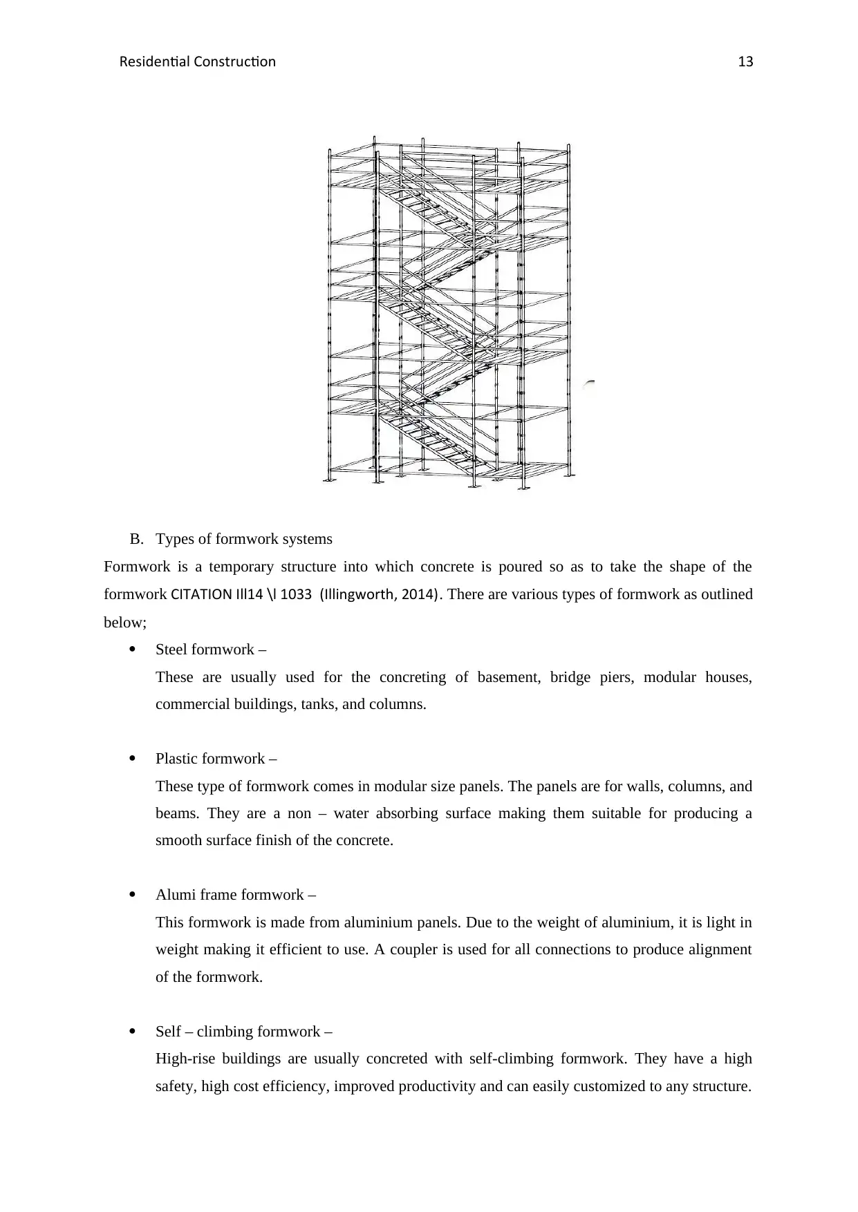
B. Types of formwork systems
Formwork is a temporary structure into which concrete is poured so as to take the shape of the
formwork CITATION Ill14 \l 1033 (Illingworth, 2014). There are various types of formwork as outlined
below;
Steel formwork –
These are usually used for the concreting of basement, bridge piers, modular houses,
commercial buildings, tanks, and columns.
Plastic formwork –
These type of formwork comes in modular size panels. The panels are for walls, columns, and
beams. They are a non – water absorbing surface making them suitable for producing a
smooth surface finish of the concrete.
Alumi frame formwork –
This formwork is made from aluminium panels. Due to the weight of aluminium, it is light in
weight making it efficient to use. A coupler is used for all connections to produce alignment
of the formwork.
Self – climbing formwork –
High-rise buildings are usually concreted with self-climbing formwork. They have a high
safety, high cost efficiency, improved productivity and can easily customized to any structure.
Paraphrase This Document
Need a fresh take? Get an instant paraphrase of this document with our AI Paraphraser

Residential Construction 14
Waffle formwork –
This formwork is used for the concreting of two-way spanning ribbed slabs. The major
advantage attributed to the use of waffle formwork is the economy of material that it uses.
The waffle moulds can be reused in other projects multiple times.
C. Role of falsework
Falsework are temporary structures that are erected to offer support to spanning or arched structures
long enough for these structures to be able to support themselves. There are three main types of
falsework systems;
Type 1 – Aluminium legs and frame falsework
Type 2 – composite material falsework (Aluminium props with timber beams)
Type 3 – Steel falsework
The design of falsework acknowledges that the members are stressed (usually up to 90% capacity)
over short time periods, and are also reused for various projects. The design also caters for tolerances
during erection and the need to provide stability CITATION And13 \l 1033 (André, et al., 2013).
Falsework normally includes temporary support structures onto which formwork that gives shape to
the concrete structure being constructed is put.
Scaffolding is also put on falsework to enable construction workers to access the structure to be
constructed and also offer a working platform for the works carried out.
The erection of falsework usually involves hoisting to a perpendicular position, then a ground crew
guides the crane operators to place the falsework in position. The final erection activity is the placing
of the deck and formwork for the structure CITATION And14 \l 1033 (André, 2014).
Falsework is used during bridge construction, to support arched sections and bridge decks in self-
anchored suspension bridges. Falsework is also used to support long spanning structures.
D. Codes for design and installation of scaffold, formwork, and falsework
The following standards are used in the design and installation of scaffolds, formwork and falsework;
AS 3610 Formwork to concrete
AS 1379 Specification and supply of concrete
Residential Construction 15
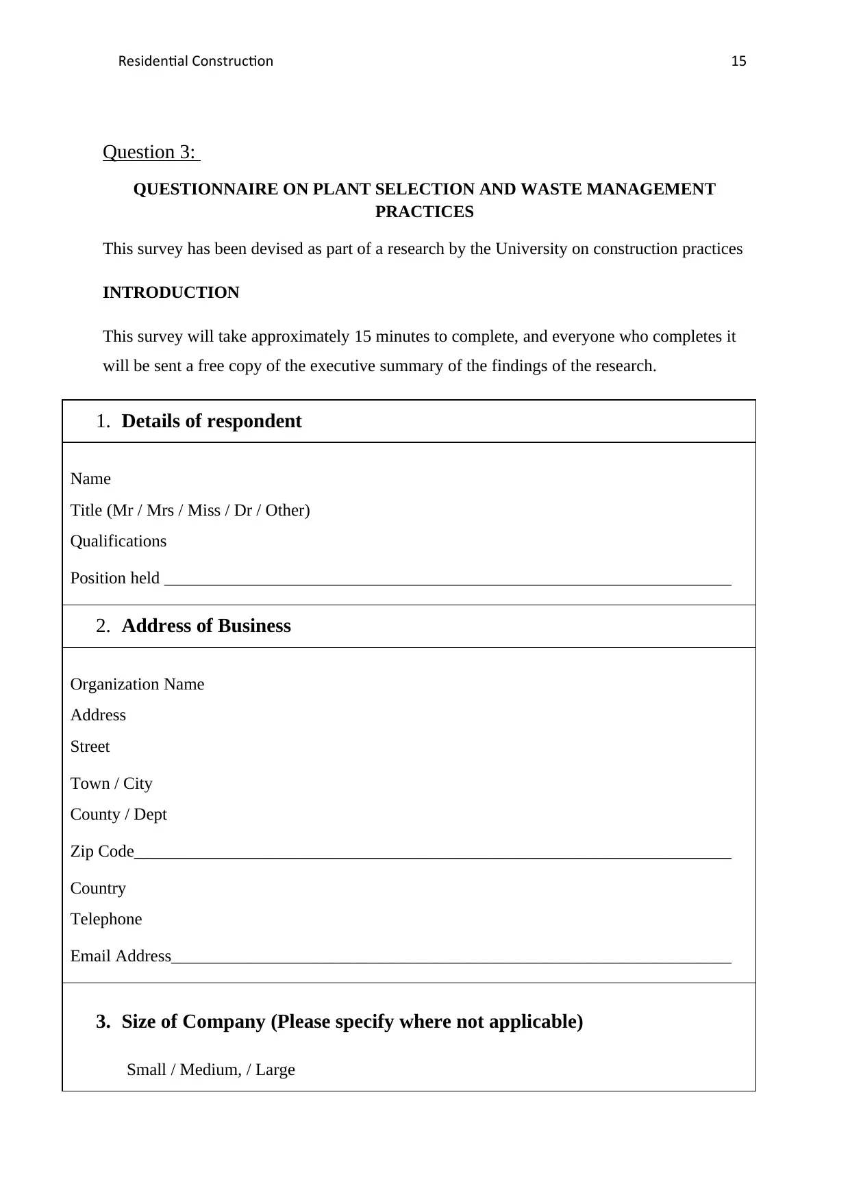
Question 3:
QUESTIONNAIRE ON PLANT SELECTION AND WASTE MANAGEMENT
PRACTICES
This survey has been devised as part of a research by the University on construction practices
INTRODUCTION
This survey will take approximately 15 minutes to complete, and everyone who completes it
will be sent a free copy of the executive summary of the findings of the research.
1. Details of respondent
Name
Title (Mr / Mrs / Miss / Dr / Other)
Qualifications
Position held ___________________________________________________________________
2. Address of Business
Organization Name
Address
Street
Town / City
County / Dept
Zip Code______________________________________________________________________
Country
Telephone
Email Address__________________________________________________________________
3. Size of Company (Please specify where not applicable)
Small / Medium, / Large
Residential Construction 16
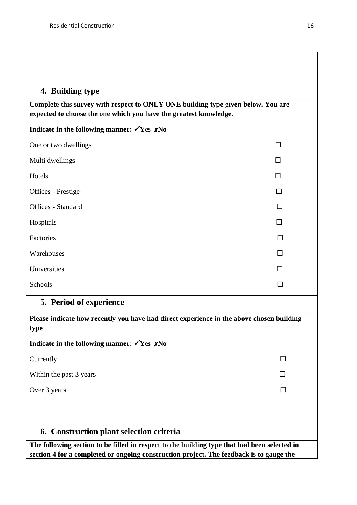
4. Building type
Complete this survey with respect to ONLY ONE building type given below. You are
expected to choose the one which you have the greatest knowledge.
Indicate in the following manner: Yes No
One or two dwellings
Multi dwellings
Hotels
Offices - Prestige
Offices - Standard
Hospitals
Factories
Warehouses
Universities
Schools
5. Period of experience
Please indicate how recently you have had direct experience in the above chosen building
type
Indicate in the following manner: Yes No
Currently
Within the past 3 years
Over 3 years
6. Construction plant selection criteria
The following section to be filled in respect to the building type that had been selected in
section 4 for a completed or ongoing construction project. The feedback is to gauge the
Secure Best Marks with AI Grader
Need help grading? Try our AI Grader for instant feedback on your assignments.
Residential Construction 17
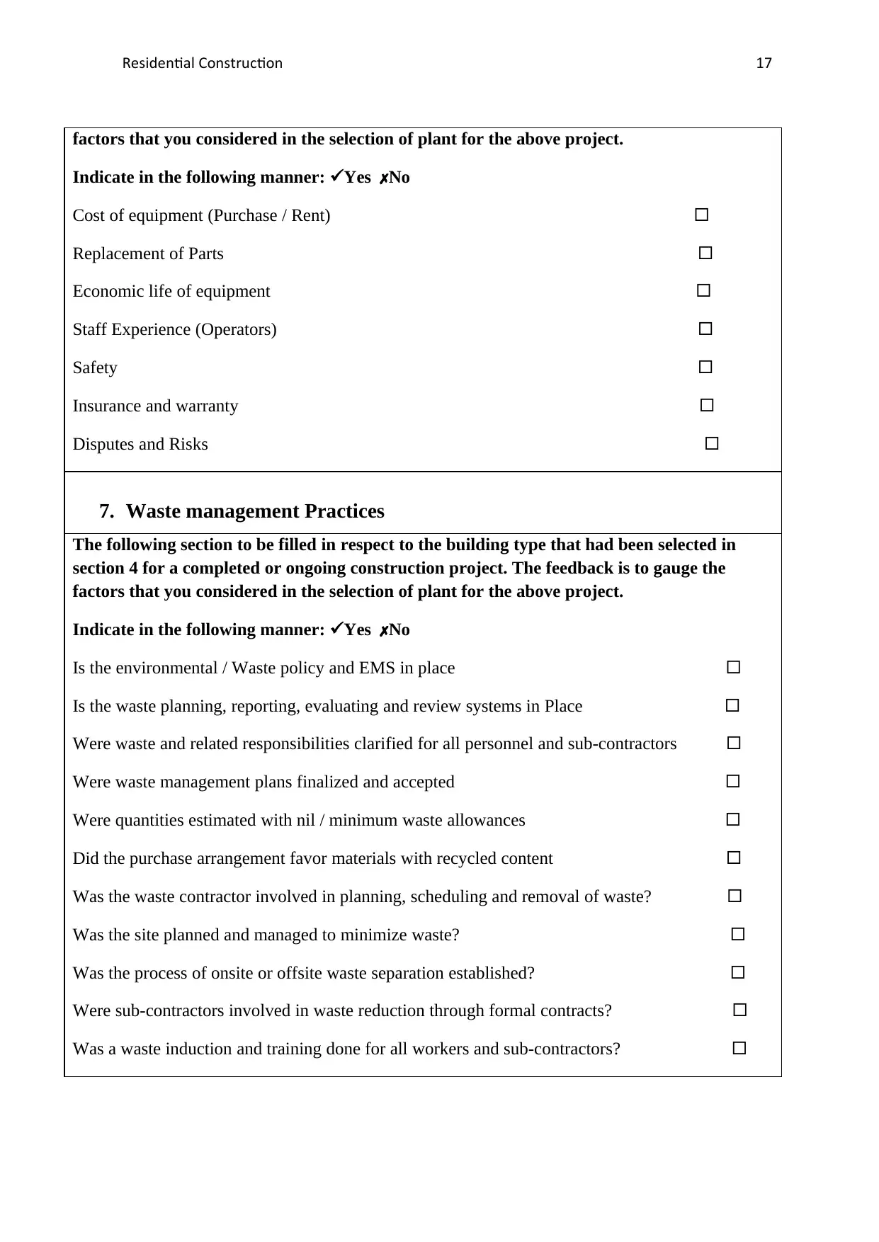
factors that you considered in the selection of plant for the above project.
Indicate in the following manner: Yes No
Cost of equipment (Purchase / Rent)
Replacement of Parts
Economic life of equipment
Staff Experience (Operators)
Safety
Insurance and warranty
Disputes and Risks
7. Waste management Practices
The following section to be filled in respect to the building type that had been selected in
section 4 for a completed or ongoing construction project. The feedback is to gauge the
factors that you considered in the selection of plant for the above project.
Indicate in the following manner: Yes No
Is the environmental / Waste policy and EMS in place
Is the waste planning, reporting, evaluating and review systems in Place
Were waste and related responsibilities clarified for all personnel and sub-contractors
Were waste management plans finalized and accepted
Were quantities estimated with nil / minimum waste allowances
Did the purchase arrangement favor materials with recycled content
Was the waste contractor involved in planning, scheduling and removal of waste?
Was the site planned and managed to minimize waste?
Was the process of onsite or offsite waste separation established?
Were sub-contractors involved in waste reduction through formal contracts?
Was a waste induction and training done for all workers and sub-contractors?
factors that you considered in the selection of plant for the above project.
Indicate in the following manner: Yes No
Cost of equipment (Purchase / Rent)
Replacement of Parts
Economic life of equipment
Staff Experience (Operators)
Safety
Insurance and warranty
Disputes and Risks
7. Waste management Practices
The following section to be filled in respect to the building type that had been selected in
section 4 for a completed or ongoing construction project. The feedback is to gauge the
factors that you considered in the selection of plant for the above project.
Indicate in the following manner: Yes No
Is the environmental / Waste policy and EMS in place
Is the waste planning, reporting, evaluating and review systems in Place
Were waste and related responsibilities clarified for all personnel and sub-contractors
Were waste management plans finalized and accepted
Were quantities estimated with nil / minimum waste allowances
Did the purchase arrangement favor materials with recycled content
Was the waste contractor involved in planning, scheduling and removal of waste?
Was the site planned and managed to minimize waste?
Was the process of onsite or offsite waste separation established?
Were sub-contractors involved in waste reduction through formal contracts?
Was a waste induction and training done for all workers and sub-contractors?
Residential Construction 18
Summary on feedback on plat selection
From the questionnaires, it is clearly seen that the major factors considered in the selection of
plant are
The cost of either buying or hiring the plant
The replacement of parts, and their availability
The operator experience
Summary on feedback on waste management
From the questionnaires, it is evident that the waste management of contractors according to
the outlined criteria is wanting.
Most contractors had an EMS outlining the erection methodology but were lacking
the environmental policy.
Waste related responsibility were also told to all participating parties in most of the
projects.
A few sites had been planned and managed to minimize waste.
Recommendation on the improvement of plant selection criteria
I recommend further scrutiny of plant before actual use on site especially on areas of safety
and the economic life of equipment.
Recommendation on the improvement of waste management criteria
I recommend a strict adherence to the waste management checklist as outlined in this
questionnaire for all contractors. Waste reduction should also be an item in formal contracts
as it is a binding agreement between the involved parties to ensure waste management.

Residential Construction 19
Conclusion:
The application of the subjects learnt in class in the field are relatable by
physical site visits to ongoing projects. This exposure helps one to better
appreciate and fathom the knowledge acquired in class. To better understand the
processes that are done during the construction phase of a project, the use of
real life examples could be helpful.
The use of questionnaire in data acquisition requires diligence. The respondents
of such surveys should carefully selected so that the researcher can have
substantial information for purposes of data analysis.
Paraphrase This Document
Need a fresh take? Get an instant paraphrase of this document with our AI Paraphraser
Residential Construction 20
References
Al-Ansari, M. S., 2017. Structural Cost of Optimized Reinforced Concrete Isolated Footing.
International Scholarly and Scientific Research & Innovation 7.4, pp. 193-200.
André, J., 2014. Determination of the main parameters affecting the performance of bridge
falsework systems, s.l.: Oxford Brookes University.
André , J., Robert, B. & António, B., 2013. Recent advances and existing challenges in the
design of bridge falsework systems. Civil Engineering and Environmental Systems,
Volume 2, pp. 130-145.
Berggren, B. & Wall, M., 2013. Calculation of thermal bridges in (Nordic) building
envelopes--Risk of performance failure due to inconsistent use of methodology.
Energy and Buildings, Volume 65, pp. 331--339.
Best, M. J., Abramowitz, G., Johnson H. R., Pitman, A. J., Balsamo, G., Boone, A., Cuntz,
M., Decharme, B., Dirmeyer, P. A., Dong, J. and Ek, M., 2015. The plumbing of land
surface models: benchmarking model performance. Journal of Hydrometeorology,
16(3), pp. 1425--1442.
Cajka, . R., Burkovic, . K. & Buchta, . V., 2014. Foundation slab in interaction with subsoil.
In: Advanced Materials Research. s.l.:Trans Tech Publ, pp. 375-380.
De Larrard, F., 2014. Concrete mixture proportioning: a scientific approach. s.l.:CRC Press.
Ghali, . A., Renaud , F. & Mamdouh , E., 2014. Concrete structures: Stresses and
deformations: Analysis and design for serviceability. s.l.:CRC Press.
Illingworth, J. R., 2014. Construction methods and planning. s.l.:CRC Press.
Janulíková, M. & Marie , S., 2013. Reducing the shear stress in the footing bottom of
concrete and masonry structures. Procedia Engineering 65 , pp. 284-289.
Karcher, J., Brenneis, C., Roddy, . C. & Benkley, J., Mar 2018. Settable compositions
comprising interground perlite and hydraulic cement. U.S, Patent No. 8,672,028.
Residential Construction 21
Lenczner, D., 2013. Elements of Loadbearing Brickwork: International Series of
Monographs in Civil Engineering. 5 ed. s.l.:Elsevier.
Nielsen, M. P. & Linh , C. H., 2016. Limit analysis and concrete plasticity. s.l.:CRC press.
Ozbakkaloglu, T., Jian, . L. & Thomas , V., 2013. FRP-confined concrete in circular sections:
Review and assessment of stress–strain models. Engineering Structures 49, pp. 1068-
1088.
Pilz, D., Poliquin, R. & Sesma, F. H., 2014 Feb. Fire-rated wall construction product. U.S,
Patent No. 8,640,415.
Reiser, B. & Tabak, I., 2014. Scaffolding. The Cambridge Handbook of the Learning
Sciences, Second Edition. s.l.:Cambridge University Press.
Wu, J., Hu , J., Terracina, D. & Ray, T., 2014. Hydraulic actuation of a downhole tool
assembly. U.S, Patent No. 8,863,843.
Zhang, . J. & Khoshnevis, B., 2013. Optimal machine operation planning for construction by
Contour Crafting. Automation in Construction, Volume 29, pp. 50-67.
1 out of 21
Related Documents


Your All-in-One AI-Powered Toolkit for Academic Success.
+13062052269
info@desklib.com
Available 24*7 on WhatsApp / Email
![[object Object]](/_next/static/media/star-bottom.7253800d.svg)
Unlock your academic potential
© 2024 | Zucol Services PVT LTD | All rights reserved.