Literature Review: Resilience Assessment in Infrastructure & Buildings
VerifiedAdded on 2023/06/14
|14
|3062
|175
Literature Review
AI Summary
This literature review delves into the assessment of resilience in infrastructure systems and building structures, particularly in the context of environmental sustainability and the timeframe following system failures or natural hazards. It traces the evolution of resilience as a theoretical framework for understanding the performance of structures under duress, highlighting its shift from a reactive approach focused on hardening and prevention to a proactive strategy encompassing disturbance prevention, recovery enhancement, and loss mitigation. Key strategies for building resilience are discussed, including the exploitation of infrastructural interdependencies, effective system restoration, rapid performance recovery, graceful degradation through control and adaptation, and proactive planning. The review examines methods for quantifying resilience, emphasizing the importance of absorptive, adaptive, and restorative capabilities. It presents mathematical formulations and graphical representations, such as resilience curves, to illustrate the transient performance of systems post-disruption. The paper concludes with an example of a blast-resistant structure design, demonstrating the application of the proposed resilience framework in real-world scenarios. Desklib offers students access to similar solved assignments and study resources.
Resilience Assessment 1
RESILIENCE ASSESSMENT IN INFRASTRUCTURE SYSTEM AND BUILDING
STRUCTURES
A Research Paper on Construction By
Student’s Name
Name of the Professor
Institutional Affiliation
City/State
Year/Month/Day
RESILIENCE ASSESSMENT IN INFRASTRUCTURE SYSTEM AND BUILDING
STRUCTURES
A Research Paper on Construction By
Student’s Name
Name of the Professor
Institutional Affiliation
City/State
Year/Month/Day
Paraphrase This Document
Need a fresh take? Get an instant paraphrase of this document with our AI Paraphraser
Resilience Assessment 2
LITERATURE REVIEW
This research paper is about resilience assessment in infrastructure system and building
structures in terms environmental sustainability and time at the occurrence of system failure or
natural hazards. Resilience has developed in the past years as a theory for perfect understanding
the infrastructures and structures performance, specifically their behaviour after and during the
disturbance occurrence caused by technical failures or natural hazards. Currently, resilience has
expanded as an approach that is proactive to enable the ability of the structures to prevent events
causing disturbances, improve the capability of recovery, and mitigate loses during occurrences,
beyond the perception of pure hardening and prevention.
Building Resilience in Infrastructure Systems
In the circumstance of infrastructure systems and building structures, resilience can be
established through concentrating on diverse stages of the performance of transient following the
occurrence of systems failure or natural hazards and the devising improvements and strategies
which strengthen the response of the system (Bueno, 2012). The strategies for a building
resilience are discussed below:
Exploitation of infrastructural interdependences: Couplings and interdependencies in operation
of structures may foster the failure propagation across the system coupled. The
interdependencies may also offer extra elasticity in interrupted conditions and extra resources
that can enable achievement of stable condition of the system that is coupled.
Effective restoration of the system: By combining the restoration strategies such as building new
elements and repairing the failed elements, the structure can attain a upper performance in regard
to the pre-disruption situations (Chang, 2010).
Resilience Assessment 3
Quick recovery of the low level of performance: Stochastic or robust maximization of the
restoration and recovery procedure during reservations in the disruption scenarios or repair
process.
Graceful degradation, i.e. control, adaptation, and self-healing: The system cannot be designed
in regard to every scenario of uncertainty, hence a resilient design should deliberate on ways of
preventing the disturbances caused by system failure from spreading across the entire structure,
creating system-wide collapse and systemic contagion. In regard to the key strategies are
engineering network system and cascading failures analysis to be used against the outbreak of
propagations and outages of cascading failures across their elements. Control engineering can
deliver strategies to create robust loops of feedback which have the ability to enable the structure
to avoid instabilities and absorb shocks. Designing topologies and structures which prevent
propagation of failures and devising flexible topologies through switching elements which
encourage degradation of system performance after disruptions are also important techniques of
enhancing resilience (Cutter, 2010).
Planning ahead in designing: Stochastic or robust maximization against ambiguous future
scenarios such as ambiguous upcoming demand or attacks in the system may be utilized in the
expansion and process of planning of the system.
Quantifying Resilience
Resilience is measured and defined based on the performance of the building structure
and infrastructure system in terms of environmental sustainability and time. The definition of
resilience can be interpreted supplementary as the capability of the structure to endure a
disorderly incident by minimizing the absorptive capability (early negative impact), by adaptive
⊘ This is a preview!⊘
Do you want full access?
Subscribe today to unlock all pages.

Trusted by 1+ million students worldwide
Resilience Assessment 4
capability (self-adaptation to them), and by restorative capability (impact recovery).
Enhancement of adaptive capability, restorative capability, and absorptive capability enhances
the resilience of the building structures and infrastructure system in terms of environmental
sustainability and time (Engineers, 2010).
It is critical to quantify and understand these abilities that encourage the structure
resilience characteristics. Restorative capability denotes the capability of an infrastructure system
to be repaired. Adaptive capability denotes an endogenous capability of a structure to adapt to
circumstances that are disruptive by self-organization so as to reduce the outcome. Emergency
structures may be used as a way of enhancing the adaptive ability of a structure. Absorptive
capabilities refer endogenous capability of the structure to minimize the undesirable
consequences triggered by occurrences and reduce the impacts. This capability can be quantified
by the use of robustness which is defined as the system’s strength to prevent disturbance
(Francis, 2014).
The enhancement of the absorptive capability can be performed through redundancy
improvement of the system, which gives another approach to the structure to function. Resilience
may be quantified through the experiment of computation in which triggering of disruptions are
performed, followed by analysis of the system performance, and then the computation of
integrated resilience metrics. Through the repetition of the process, numerous solutions of
structure design may be graded in regard to resilience. Similarly, resilience against numerous
disturbances can be evaluated and strategies of resilience improvement compared (Haimes,
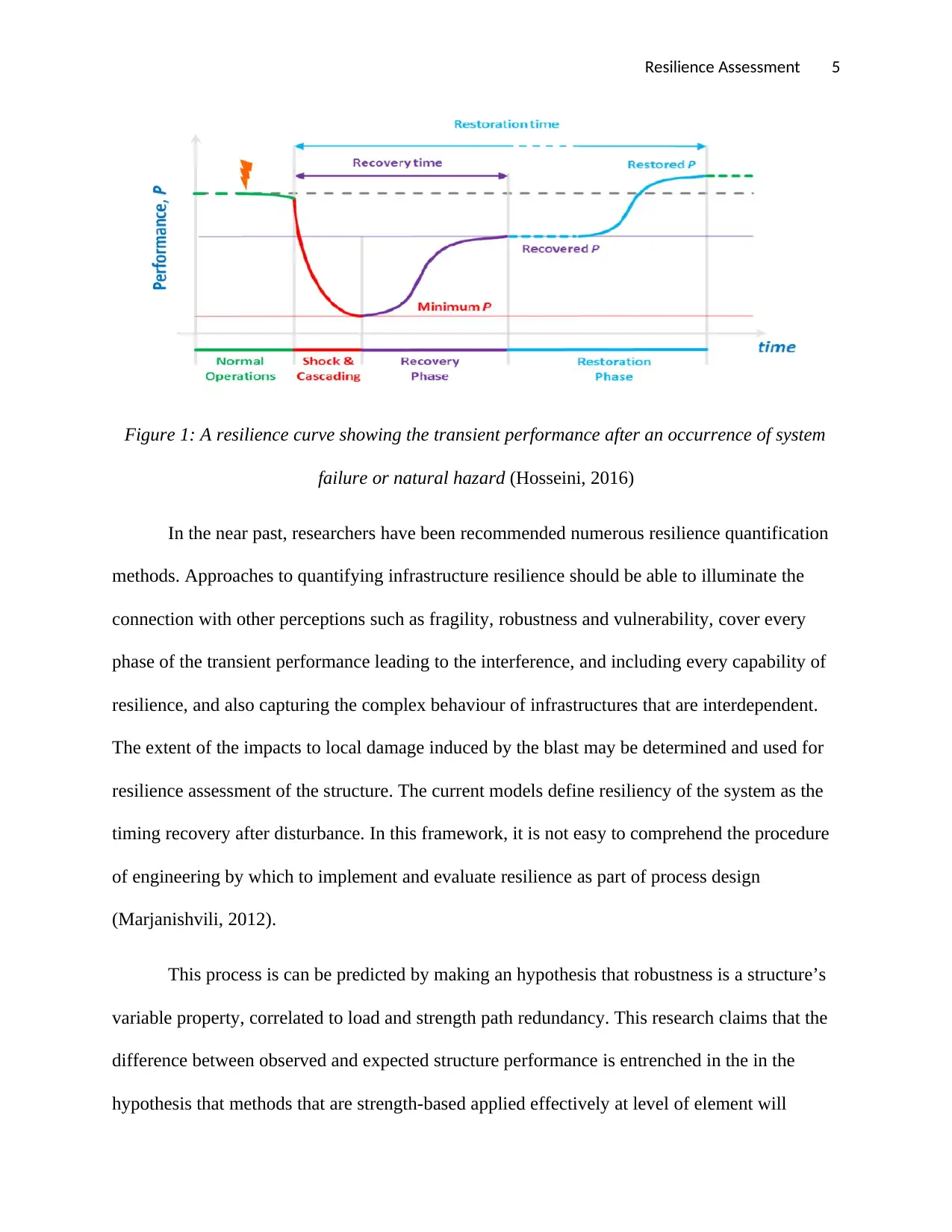
2010). The figure below is a resilience curve showing the transient performance after an
occurrence of system failure or natural hazard:
Paraphrase This Document
Need a fresh take? Get an instant paraphrase of this document with our AI Paraphraser
Resilience Assessment 5
Figure 1: A resilience curve showing the transient performance after an occurrence of system
failure or natural hazard (Hosseini, 2016)
In the near past, researchers have been recommended numerous resilience quantification
methods. Approaches to quantifying infrastructure resilience should be able to illuminate the
connection with other perceptions such as fragility, robustness and vulnerability, cover every
phase of the transient performance leading to the interference, and including every capability of
resilience, and also capturing the complex behaviour of infrastructures that are interdependent.
The extent of the impacts to local damage induced by the blast may be determined and used for
resilience assessment of the structure. The current models define resiliency of the system as the
timing recovery after disturbance. In this framework, it is not easy to comprehend the procedure
of engineering by which to implement and evaluate resilience as part of process design
(Marjanishvili, 2012).
This process is can be predicted by making an hypothesis that robustness is a structure’s
variable property, correlated to load and strength path redundancy. This research claims that the
difference between observed and expected structure performance is entrenched in the in the
hypothesis that methods that are strength-based applied effectively at level of element will
Resilience Assessment 6
sufficiently change the global opposition from which robustness of the structure is consequent.
Rather than considering the resistance as a scale of sliding relative to a load that is fixed, the
alternative recommended is to deliberate the robustness as a static structure that is tied
exceptionally to the alignment of the structure as shown in the equation below:
Robustness = f(geometry, topology) …………………………………………. (i)
In this robustness formulation, geometry denoted the outline of the load-bearing components of
the structure (Moe, 2012).
Topology denotes the configuration of building the shell to the site. This topology
denoted the expected structure exposure to the local or widespread concentration of great loads.
Both topology and geometry are absolute features that cannot be varied without alterations to the
whole configuration of the structure. After the geometry of the infrastructure, the system has
been defined, the robustness of the structure will also be defined. In case robustness is held to be
the absolute property of the structure, resilience denotes the property variable that varies with
precise design decisions. Resilience pursuit is normally deliberated to be a balancing exercise of
a given infrastructure to recover, adapt, and resist events that are extreme as shown in equation 2
below:
Resilience = f(recovery, adaptation, resistance)…………………………………… (ii)
Resilience = f(robustness, hazard)
= f(geometry, topology, hazard)………………………………………. (iii)
The component of resistance in the equation (ii) above denotes effort in engineering to
resist hazard prescribed. The resistance of the load enables the system to attain faster recovery to
an extensive threat range by evading failure (Ouyang, 2015). It is likely that even structures that
are robust may experience some failure when subjected to dangerous loads on the design levels.
⊘ This is a preview!⊘
Do you want full access?
Subscribe today to unlock all pages.

Trusted by 1+ million students worldwide
Resilience Assessment 7
Resistance should be issued potential damages reduces causalities and minimize the chances of
serious physical losses. The component of recovery denotes the procedure over duration in which
the function of the structure is restored through replacement or repair. The component of
adaptation is greatly known to comprise of efforts of emergency planning of high level to
reinstate the structure after the occurrence of the damage. The balance perceived of these
variable as it impacts resilience of the system is depicted visually. Equation (iii) shows the
common resilience expression to exclude the components of adaptation and recovery (Sadek,
2009).
In the modified resilience expression, the performance of the structure related with a
given alignment is deliberated to be independent of the component strengthening support to
address a hazard or load prescribed. The resultant resilience equation denotes the specific
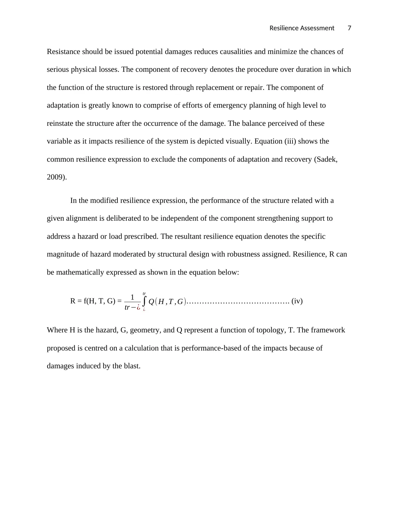
magnitude of hazard moderated by structural design with robustness assigned. Resilience, R can
be mathematically expressed as shown in the equation below:
R = f(H, T, G) = 1
tr−¿ ∫
¿
tr
Q( H , T , G)…………………………………. (iv)
Where H is the hazard, G, geometry, and Q represent a function of topology, T. The framework
proposed is centred on a calculation that is performance-based of the impacts because of
damages induced by the blast.
Paraphrase This Document
Need a fresh take? Get an instant paraphrase of this document with our AI Paraphraser
Resilience Assessment 8
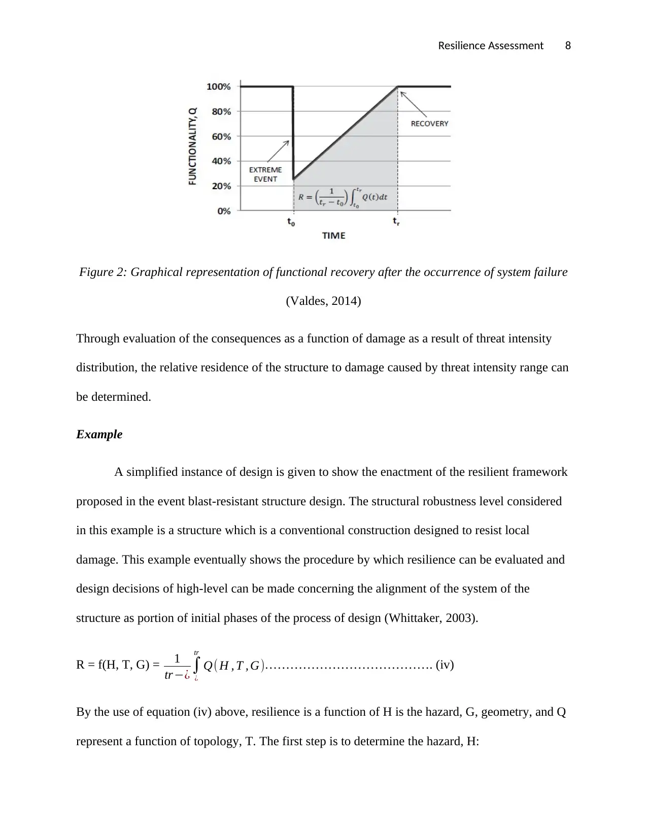
Figure 2: Graphical representation of functional recovery after the occurrence of system failure
(Valdes, 2014)
Through evaluation of the consequences as a function of damage as a result of threat intensity
distribution, the relative residence of the structure to damage caused by threat intensity range can
be determined.
Example
A simplified instance of design is given to show the enactment of the resilient framework
proposed in the event blast-resistant structure design. The structural robustness level considered
in this example is a structure which is a conventional construction designed to resist local
damage. This example eventually shows the procedure by which resilience can be evaluated and
design decisions of high-level can be made concerning the alignment of the system of the
structure as portion of initial phases of the process of design (Whittaker, 2003).
R = f(H, T, G) = 1
tr−¿ ∫
¿
tr
Q( H , T , G)…………………………………. (iv)
By the use of equation (iv) above, resilience is a function of H is the hazard, G, geometry, and Q
represent a function of topology, T. The first step is to determine the hazard, H:
Resilience Assessment 9
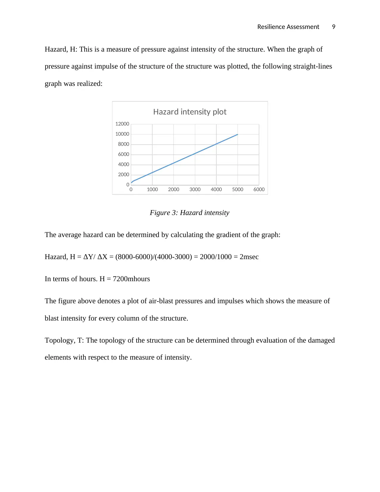
Hazard, H: This is a measure of pressure against intensity of the structure. When the graph of
pressure against impulse of the structure of the structure was plotted, the following straight-lines
graph was realized:
0 1000 2000 3000 4000 5000 6000
0
2000
4000
6000
8000
10000
12000
Hazard intensity plot
Figure 3: Hazard intensity
The average hazard can be determined by calculating the gradient of the graph:
Hazard, H = ΔY/ ΔX = (8000-6000)/(4000-3000) = 2000/1000 = 2msec
In terms of hours. H = 7200mhours
The figure above denotes a plot of air-blast pressures and impulses which shows the measure of
blast intensity for every column of the structure.
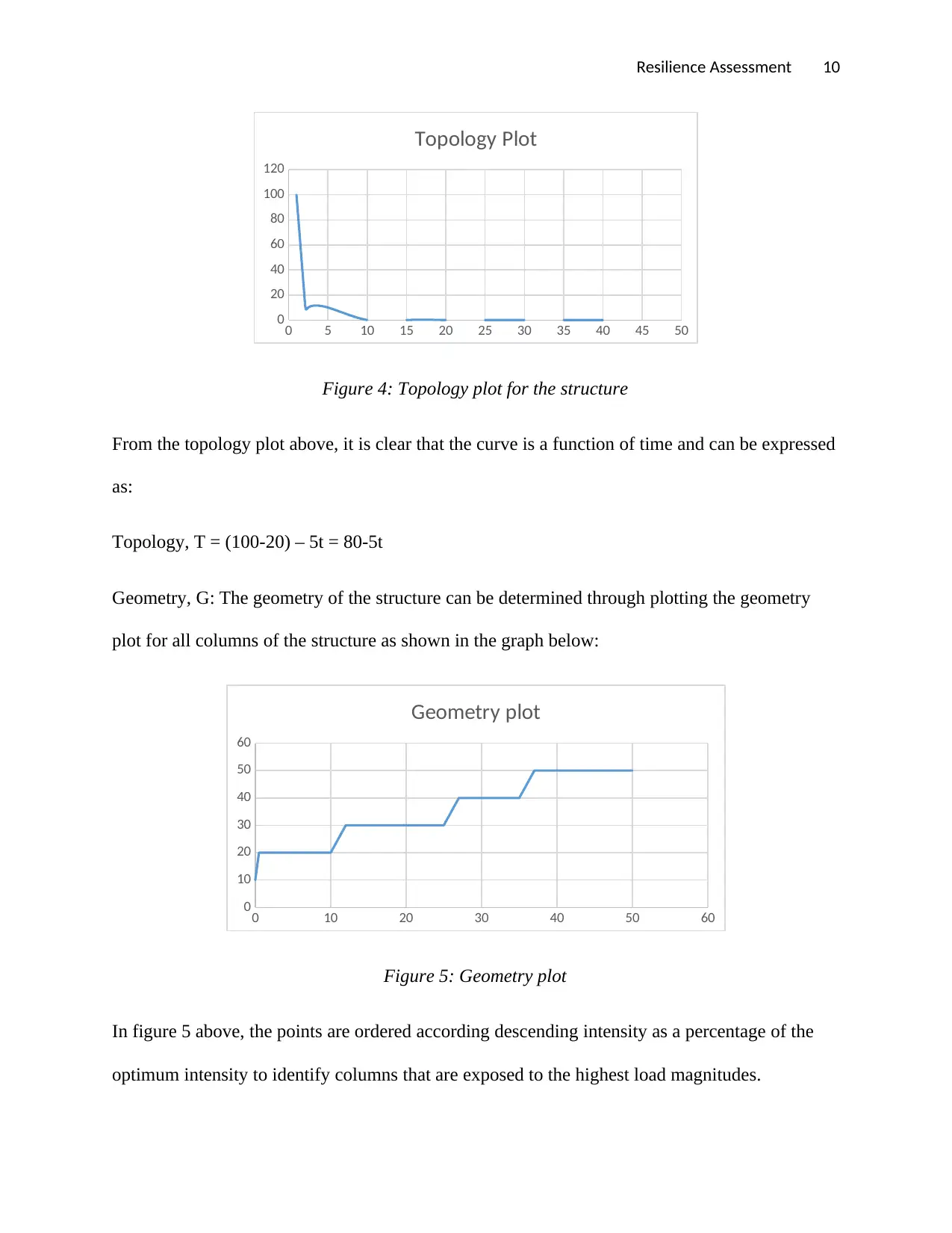
Topology, T: The topology of the structure can be determined through evaluation of the damaged
elements with respect to the measure of intensity.
⊘ This is a preview!⊘
Do you want full access?
Subscribe today to unlock all pages.

Trusted by 1+ million students worldwide
Resilience Assessment 10
0 5 10 15 20 25 30 35 40 45 50
0
20
40
60
80
100
120
Topology Plot
Figure 4: Topology plot for the structure
From the topology plot above, it is clear that the curve is a function of time and can be expressed
as:
Topology, T = (100-20) – 5t = 80-5t
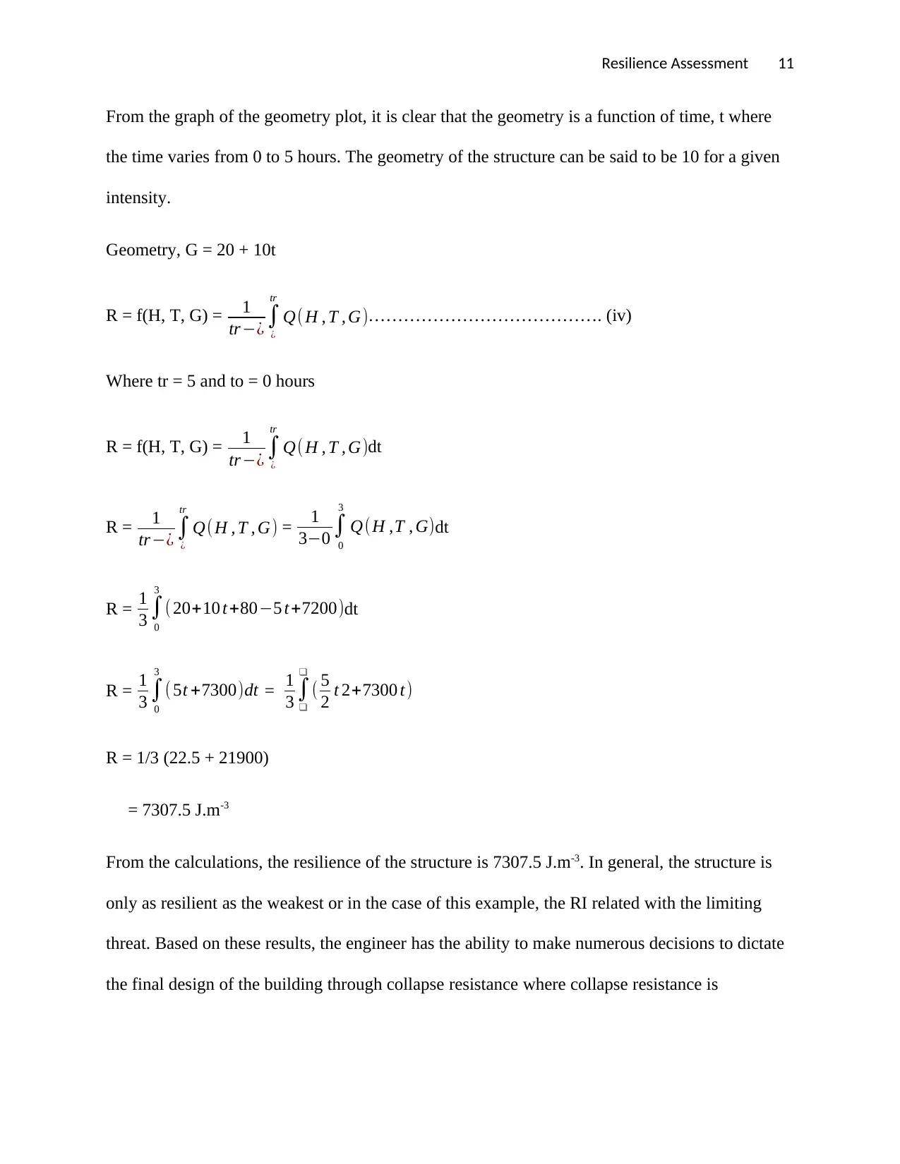
Geometry, G: The geometry of the structure can be determined through plotting the geometry
plot for all columns of the structure as shown in the graph below:
0 10 20 30 40 50 60
0
10
20
30
40
50
60
Geometry plot
Figure 5: Geometry plot
In figure 5 above, the points are ordered according descending intensity as a percentage of the
optimum intensity to identify columns that are exposed to the highest load magnitudes.
Paraphrase This Document
Need a fresh take? Get an instant paraphrase of this document with our AI Paraphraser
Resilience Assessment 11
From the graph of the geometry plot, it is clear that the geometry is a function of time, t where
the time varies from 0 to 5 hours. The geometry of the structure can be said to be 10 for a given
intensity.
Geometry, G = 20 + 10t
R = f(H, T, G) = 1
tr−¿ ∫
¿
tr
Q( H , T , G)…………………………………. (iv)
Where tr = 5 and to = 0 hours
R = f(H, T, G) = 1
tr−¿ ∫
¿
tr
Q( H , T , G)dt
R = 1
tr−¿ ∫
¿
tr
Q( H , T , G) = 1
3−0 ∫
0
3
Q(H ,T , G)dt
R = 1
3 ∫
0
3
( 20+10 t+80−5 t+7200)dt
R = 1
3 ∫
0
3
( 5t +7300)dt = 1
3 ∫
❑
❑
( 5
2 t 2+7300 t)
R = 1/3 (22.5 + 21900)
= 7307.5 J.m-3
From the calculations, the resilience of the structure is 7307.5 J.m-3. In general, the structure is
only as resilient as the weakest or in the case of this example, the RI related with the limiting
threat. Based on these results, the engineer has the ability to make numerous decisions to dictate
the final design of the building through collapse resistance where collapse resistance is
Resilience Assessment 12
implemented and accept results for a given threats or proceeding with conventional design for
the frame and accept results for the specific threats.
Conclusion
This research paper discusses the resilience assessment in infrastructure system and
building structures in terms environmental sustainability and time at the occurrence of system
failure or natural hazards. The resilience concept can be defined as a degree of the structure
persistence and the capability to absorb disturbances and change and still retain in the similar
relations between state variables or populations. The definition of resilience can be interpreted
further as the capability of the structure to endure an event that is disruptive by minimizing the
absorptive capability (primary negative impact), by adaptive capability (self-adaptation to them),
and by restorative capability (impact recovery).
⊘ This is a preview!⊘
Do you want full access?
Subscribe today to unlock all pages.

Trusted by 1+ million students worldwide
1 out of 14
Your All-in-One AI-Powered Toolkit for Academic Success.
+13062052269
info@desklib.com
Available 24*7 on WhatsApp / Email
![[object Object]](/_next/static/media/star-bottom.7253800d.svg)
Unlock your academic potential
Copyright © 2020–2025 A2Z Services. All Rights Reserved. Developed and managed by ZUCOL.