Competency Demonstration Report on RFID Antenna Design Project
VerifiedAdded on 2020/02/24
|8
|1644
|103
Report
AI Summary
This report is a Competency Demonstration Report (CDR) detailing a project focused on the design and analysis of a UHF RFID tag antenna. The project aimed to enhance the read range of the antenna by matching the impedance of the RFID chip and the antenna. The report covers the project's background, objectives, and the student's role, including responsibilities in developing the antenna model, performing simulations using COMSOL Multiphysics, and optimizing the design. The report also discusses the theoretical concepts behind RFID technology, the engineering skills applied, challenges faced during simulation, and collaborative efforts with team members. The student successfully developed a COMSOL model, validated the antenna design, and improved the read range. The project involved determining the appropriate criteria for impedance matching, developing formulas, and simulating the antenna's performance to achieve the desired results. The report highlights the student's contributions, including the implementation and fabrication of the RFID tag antenna, along with the calculations and physical tests conducted to determine the antenna's enhanced efficiency.

Competency Demonstration Report (CDR)
Career Episode 1
Career Episode 1
Paraphrase This Document
Need a fresh take? Get an instant paraphrase of this document with our AI Paraphraser
CE 1.1: Project Introduction
Name of the Project : Chip Impedance Matching for UHF RFID Tag Antenna
Design
Geographical Location : [Please Fill]
Project Duration : [Please Fill]
Organization : [Please Fill]
Position in the Project : Team Member
CE 1.2: Project Background
CE 1.2.1: Characteristics of the Project
In the recent days, the advancement of wireless technology has resulted in the increased
use of RFID (Radiofrequency Identification) technology. In most cases, the RFID tags are used
for controlling and monitoring various processes. Apart from that, the touch less and wireless
technologies used in various stores and banking sectors utilizes the RFID technology. While
evaluating and studying about the wireless RFID tag antenna, I have observed the significant
limitation of the antennas is the smaller read range and the high power consumed for operations.
Therefore, I took this project for increasing the read range while reducing the antenna size for
providing more compact antenna design. For maximizing the read range of the RFID, I have
matched the impedance of the chip used in the RFID tag along with the impedance of the
antenna used in the RFID tag.
Page 1 of 8
CE 1.2.2: Objectives developed for project
In this project I have aimed to increase the read range of the RFID tag antenna. For the
design and analysis I have considered the use of UHF RFID antenna. In UHF RFID antenna, the
microchip antennas are integrated within the tag itself. For the increment of the read range of the
antenna, I have observed that it is essential to match the impedance level of both the tag and the
antenna integrated within the RFID tag. For the successful completion of the project, I have
developed the following objectives as follows:
To determine the appropriate functional process used in RFID antennas;
To match the impedance of the tag and the antenna integrated with the UHF RFID
antenna;
To increase the read range of the RFID tag antennas;
To integrate the COMSOL model for increasing the read range and matching the
antenna impedance;
To validate the proposed design of the antenna;
To optimize the design of the RFID tag antenna;
CE 1.2.3: My area of work
I have studied various processes and working procedure of the RFID tag antenna. In
addition to that, I have identified the various process and factors used in the RFID tag antenna
for improving the read range and matching the impedance of the tag and antenna. Apart from
that, I have identified the criteria and formula for matching the impedance and determining the
read range of the antenna. Furthermore, I have used COMSOL Multiphysic for simulating the
developed antenna and proposed model.
Page 2 of 8
⊘ This is a preview!⊘
Do you want full access?
Subscribe today to unlock all pages.

Trusted by 1+ million students worldwide
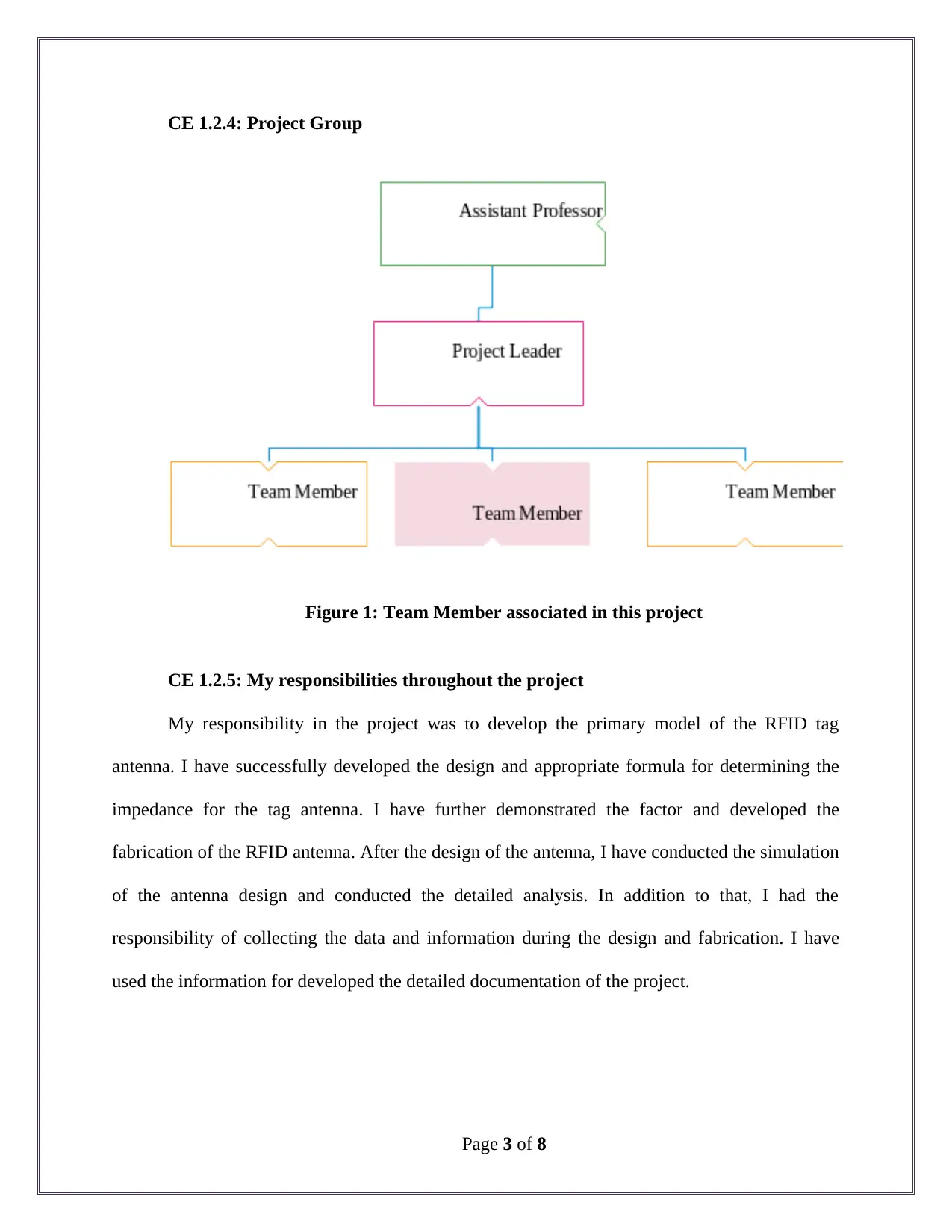
CE 1.2.4: Project Group
Figure 1: Team Member associated in this project
CE 1.2.5: My responsibilities throughout the project
My responsibility in the project was to develop the primary model of the RFID tag
antenna. I have successfully developed the design and appropriate formula for determining the
impedance for the tag antenna. I have further demonstrated the factor and developed the
fabrication of the RFID antenna. After the design of the antenna, I have conducted the simulation
of the antenna design and conducted the detailed analysis. In addition to that, I had the
responsibility of collecting the data and information during the design and fabrication. I have
used the information for developed the detailed documentation of the project.
Page 3 of 8
Paraphrase This Document
Need a fresh take? Get an instant paraphrase of this document with our AI Paraphraser
CE 1.3: Distinctive Activity
CE 1.3.1: Comprehending the Theory of the project
The technology of RFID utilizes the non-contact wireless application of the
electromagnetic radio-frequency fields for transforming data and signals. The UHF RFID
antenna consists of an integrated circuit chip and integrated antenna within it. The chip
integrated within the RFID obtains power from the antenna and operates with the input
impedance variance. I have observed that the backscattered of the signal are developed with the
data during the transmission. Orientation sensitivity and maximum rage reach are the two major
characteristics of the RFID tags. For achieving the optimum operating performance of the
antenna, the impedance of the antenna is required to meet with the impedance of the RFID chip.
CE 1.3.2: Engineering Knowledge and Skills applied in the project
I have worked in this project for determining the appropriate criteria for matching the
impedance of the antenna and RFID tag. For this process, I have indicated Zc for the chip
impedance and Za as the antenna impedance. Nevertheless, for evaluating Zc and Za, I have
considered
Zc = Rc + jXc
Za = Ra + jXa
In the above equations, I have used Ra and Rc for denoting the antenna and chip
resistance respectively. On the other hand, I have used Xa and Xc as the antenna resistance and
chip resistance respectively. I have utilized the voltage supply as a particular open circuit RF
Page 4 of 8
(radiofrequency) and used it for interrogating the antenna’s electromagnetic field. Furthermore, I
have utilized the impedance of the chip and varied the value with the power absorbed by the
RFID chip. I have identified the effect due to the energy sapping between RFID chip and antenna
embedded in the RFID tag. Apart from that, for identifying the power that is being absorbed by
the antenna, I have developed the equation with the following equation:
Pc = Pa τ
In the above equation, I have used τ for indicating the coefficient of transmission power,
Pa as the power available from the antenna, and Pc as the power consumed by the antenna.
Through this, I was able to identify the appropriate power consumed and the impedance of the
RIFD antenna and tag.
CE 1.3.3: Accomplishment and Task Performed
I have developed the criteria and modle for matching the impedance of the antenna and
RFID tag while determining the maximum read range of the RFID data. I have developed the
approriate formula for determining and the range and impedance of the antenna.
CE 1.3.4: Identified Issues and Their Solutions
Issue: I have selected the application of COMSOL Multiphysics for conducting the
simulation of the developed RFID antenna. I have faced significant issue while including the
substrate, chip geometry and antenna design and properties in the simulation model. The lack of
information about the simulation model and little experience working with the simulation system
has created the issue with the project.
Page 5 of 8
⊘ This is a preview!⊘
Do you want full access?
Subscribe today to unlock all pages.

Trusted by 1+ million students worldwide
Solution: in order to overcome with the issue, I have communicated with the assistant
professor who was guiding me through the project. Based on the information and guidance of the
professor I have learnt the application of COMSOL Multiphysics. Through this, I was able to
input the antenna gain and transmitter power of the antenna along with the operating frequency
of the RFID tag. This has allowed me in successfully develop the COMSOL model for
simulation.
CE 1.3.5: Plan for producing creative and innovative work
I have optimized the antenna in this project in order to create innovative and creative
work. After the validation of the RFID model, I have optimized the system and conducted test
with security card system. For conducting the simulation process, I have kept the frequency of
the chip at 866.5 MHz and impedance of the chip at 15-45j . During the optimization of the
objective function, I have maximized the value of the power transmission coefficient. For the
optimization of the antenna design, I have used two methods including Monte Carlo optimization
and bound optimization method. During the simulation process, I have used BOBYQA solver for
developing the geometric design of the antenna. Through this, I was able to improve the antenna
design and the coefficient of power transmission. Through this process, I was successful in
simulate and match the impedance of RFID tag and antenna.
CE 1.3.6: Collaborative work
I have worked along with three other team members for the implementation and
fabrication of the antenna design. I have initiated regular meetings and brainstorming session
with the team members for identifying any technical solutions and plan for developing the
Page 6 of 8
Paraphrase This Document
Need a fresh take? Get an instant paraphrase of this document with our AI Paraphraser
antenna design. I have further discussed any issue observed during the fabrication of the antenna
design and matching the impedance.
CE 1.4: Project Review
CE 1.4.1: Project Overview
During this project, I was successful in developing the COMSOL model of the antenna. I
was successful in validating the model of the proposed antenna in this project. I have calculated
and conducted the physical test for determining the enhanced efficiency and performance of the
antenna. Through this project, I was successful in matching the impedance of the RFID tag and
antenna in the system. Furthermore, the read range of the RFID tag was also improved.
CE 1.4.2: My contribution to work
In this project, I have worked for the implementation and fabrication of the RFID tag
antenna for this project. With the application of the theoretical knowledge and practical
implementation I was successful in developing the RFID antenna. In addition to that, I have
computed the maximum range of the read and found improvement in the range read of the
antenna.
Page 7 of 8
1 out of 8
Related Documents
Your All-in-One AI-Powered Toolkit for Academic Success.
+13062052269
info@desklib.com
Available 24*7 on WhatsApp / Email
![[object Object]](/_next/static/media/star-bottom.7253800d.svg)
Unlock your academic potential
Copyright © 2020–2025 A2Z Services. All Rights Reserved. Developed and managed by ZUCOL.


