Rotary Air Compressor Design Optimisation for Energy Storage System
VerifiedAdded on 2023/06/12
|18
|3987
|384
Literature Review
AI Summary
This literature review focuses on the design optimisation and application of rotary air compressors, particularly for compressed air energy storage systems. It begins by highlighting the increasing use of renewable energy sources and the importance of energy storage solutions like compressed air energy storage. The review discusses the history and evolution of screw compressors, emphasizing their advantages over other types of compressors. It delves into the geometry of screw compressors, explaining the rotor profiling procedure and the significance of various parameters in rotor design. The thermodynamic processes within the compressor are also examined, including the equations governing energy conversion and mass continuity. The review further explores the impact of oil injection on compressor performance and the use of computational methods for design optimisation. The study concludes by emphasizing the potential for multivariable optimisation of compressor design and rotor profile to enhance efficiency and performance, making it relevant for applications in compressed air energy storage and other industrial processes. This document is available on Desklib, a platform offering a wide array of study resources, including past papers and solved assignments.
DESIGN OPTIMISATION AND APPLICATION OF ROTARY AIR COMPRESSOR
Name of Student
Institution Affiliation
DESIGN OPTIMISATION AND APPLICATION OF ROTARY AIR COMPRESSOR 1
Name of Student
Institution Affiliation
DESIGN OPTIMISATION AND APPLICATION OF ROTARY AIR COMPRESSOR 1
Paraphrase This Document
Need a fresh take? Get an instant paraphrase of this document with our AI Paraphraser
Literature review
Title
Application and design optimization of rotary air compressor for compressed air for the
compressed air energy storage system.
Abstract
The twin-screw air compressor is a positive displacement machine applied in
compression of gases and other fluids to moderate pressures or high pressures. It has two
identical intermeshing rotors with helical grooves. The rotors then have a fitting casing that is
separated from them by a very small clearance. During the compression process, some types are
lubricated or injected with oil or other fluids while others are not. Over the last few years since
their invention, screw compressors have been rapidly and widely accepted in the market and
preferred over other types of positive displacement machines due to their higher efficiency,
higher reliability, longer service life, compactness as well as higher rotational speeds.
Various computer packages and software have been developed to easily determine and
optimize the performance of various rotor profiles. This is a great achievement since previously
experiments were used to evaluate the performance of various profiles. These experiments are
tedious and time-consuming and not as accurate as the computerized methods. This paper
discusses the use of a computer package for rotor profile optimization.
1. Introduction
Currently, many industries and homes are resolving to use the alternative sources of
energy which are renewable and environmentally friendly. People and industries are currently
storing energy such that in case there is the need for an alternative energy to boost the supply of
DESIGN OPTIMISATION AND APPLICATION OF ROTARY AIR COMPRESSOR 2
the grid, then these energy storage devices are used. Some of the energy storage devices that are
currently being used include flywheel energy storage system, pumped-hydro, battery energy
storage, and compressed air energy storage systems.
In 1928 was the year when the first theory of gas compression was developed by a
Japanese scholar, Nahuse. However, the first practical compressor was invented later in 1934 a
Swedish by the name Lysholm. This compressor had a 3/3 profile combination. Later on, many
improvements were seen on the subsequent compressor designs. The twin-screw rotary
compressor came into existence in 1960. It came along with many benefits such as lower cost,
reduced size, higher capacity as well as options for high compression ratios operation. In the
recent past, a lot of studies and research has been conducted on techniques for improving the
rotor design and adiabatic and volumetric efficiencies (Wan et al, 2017).
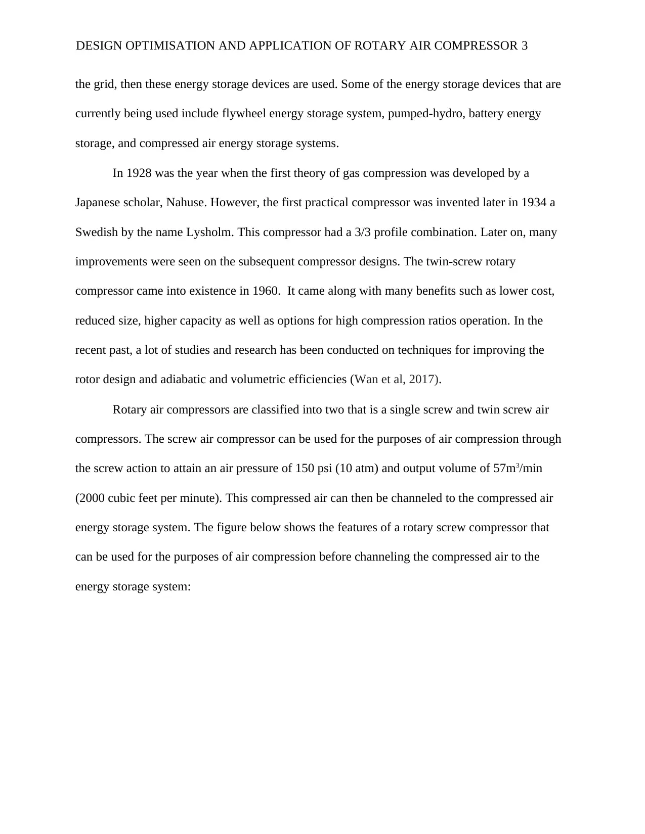
Rotary air compressors are classified into two that is a single screw and twin screw air
compressors. The screw air compressor can be used for the purposes of air compression through
the screw action to attain an air pressure of 150 psi (10 atm) and output volume of 57m3/min
(2000 cubic feet per minute). This compressed air can then be channeled to the compressed air
energy storage system. The figure below shows the features of a rotary screw compressor that
can be used for the purposes of air compression before channeling the compressed air to the
energy storage system:
DESIGN OPTIMISATION AND APPLICATION OF ROTARY AIR COMPRESSOR 3
currently being used include flywheel energy storage system, pumped-hydro, battery energy
storage, and compressed air energy storage systems.
In 1928 was the year when the first theory of gas compression was developed by a
Japanese scholar, Nahuse. However, the first practical compressor was invented later in 1934 a
Swedish by the name Lysholm. This compressor had a 3/3 profile combination. Later on, many
improvements were seen on the subsequent compressor designs. The twin-screw rotary
compressor came into existence in 1960. It came along with many benefits such as lower cost,
reduced size, higher capacity as well as options for high compression ratios operation. In the
recent past, a lot of studies and research has been conducted on techniques for improving the
rotor design and adiabatic and volumetric efficiencies (Wan et al, 2017).
Rotary air compressors are classified into two that is a single screw and twin screw air
compressors. The screw air compressor can be used for the purposes of air compression through
the screw action to attain an air pressure of 150 psi (10 atm) and output volume of 57m3/min
(2000 cubic feet per minute). This compressed air can then be channeled to the compressed air
energy storage system. The figure below shows the features of a rotary screw compressor that
can be used for the purposes of air compression before channeling the compressed air to the
energy storage system:
DESIGN OPTIMISATION AND APPLICATION OF ROTARY AIR COMPRESSOR 3
⊘ This is a preview!⊘
Do you want full access?
Subscribe today to unlock all pages.
Trusted by 1+ million students worldwide
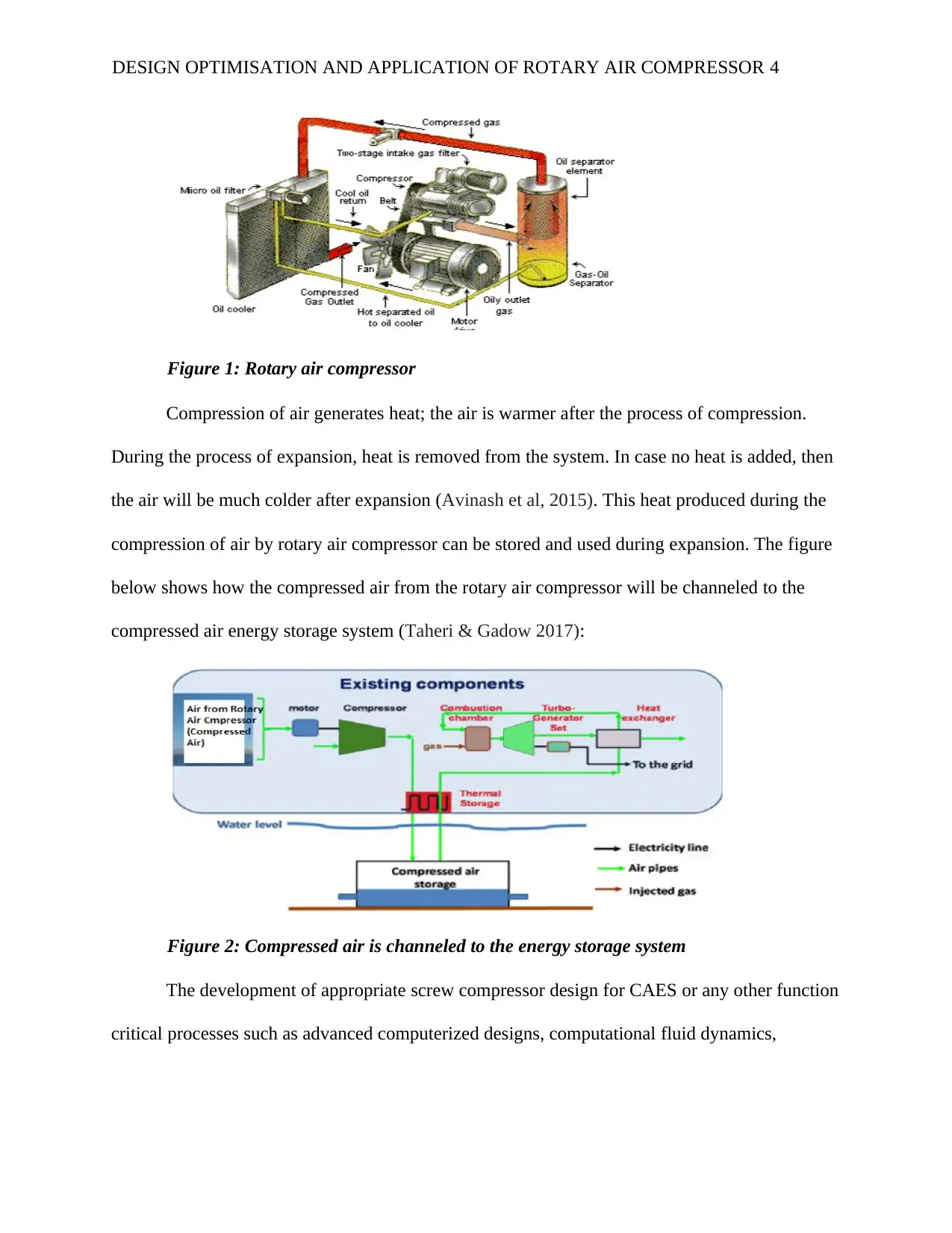
Figure 1: Rotary air compressor
Compression of air generates heat; the air is warmer after the process of compression.
During the process of expansion, heat is removed from the system. In case no heat is added, then
the air will be much colder after expansion (Avinash et al, 2015). This heat produced during the
compression of air by rotary air compressor can be stored and used during expansion. The figure
below shows how the compressed air from the rotary air compressor will be channeled to the
compressed air energy storage system (Taheri & Gadow 2017):
Figure 2: Compressed air is channeled to the energy storage system
The development of appropriate screw compressor design for CAES or any other function
critical processes such as advanced computerized designs, computational fluid dynamics,
DESIGN OPTIMISATION AND APPLICATION OF ROTARY AIR COMPRESSOR 4
Paraphrase This Document
Need a fresh take? Get an instant paraphrase of this document with our AI Paraphraser
mathematical modelling, and experimental validation amongst others (Byeon et al, 2017). This
paper focusses on mathematical modelling and advanced computerized design tool to optimize a
better screw compressor for the compressed air energy storage and other applications. Screw
machines are gaining popularity today for fluid compression and expansion jobs and are
continuously replacing vane and reciprocating compressors (Bianchi et al, 2015). This calls for
more research on design optimisation in order to come up with the ultimate best design that has
higher adiabatic and volumetric efficiencies.
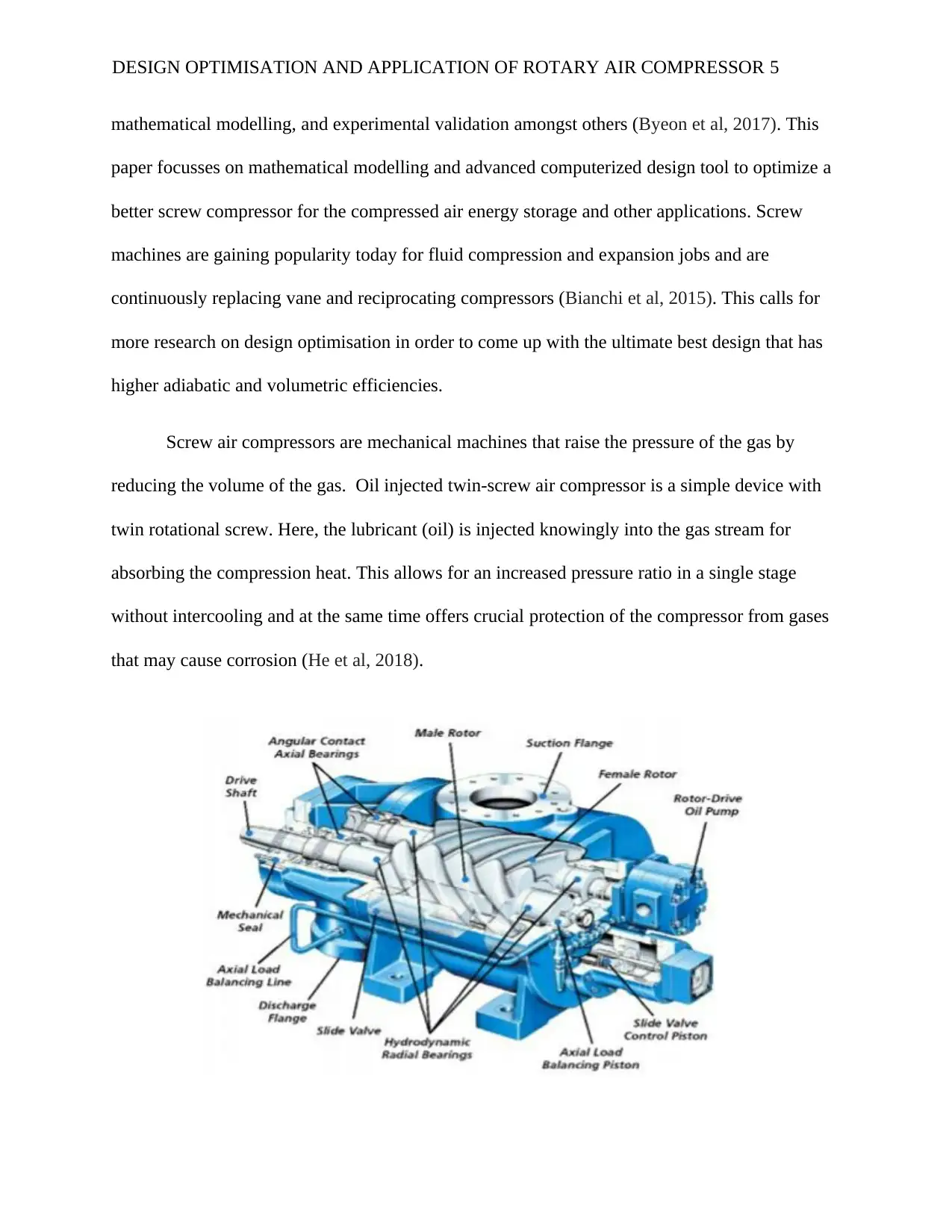
Screw air compressors are mechanical machines that raise the pressure of the gas by
reducing the volume of the gas. Oil injected twin-screw air compressor is a simple device with
twin rotational screw. Here, the lubricant (oil) is injected knowingly into the gas stream for
absorbing the compression heat. This allows for an increased pressure ratio in a single stage
without intercooling and at the same time offers crucial protection of the compressor from gases
that may cause corrosion (He et al, 2018).
DESIGN OPTIMISATION AND APPLICATION OF ROTARY AIR COMPRESSOR 5
paper focusses on mathematical modelling and advanced computerized design tool to optimize a
better screw compressor for the compressed air energy storage and other applications. Screw
machines are gaining popularity today for fluid compression and expansion jobs and are
continuously replacing vane and reciprocating compressors (Bianchi et al, 2015). This calls for
more research on design optimisation in order to come up with the ultimate best design that has
higher adiabatic and volumetric efficiencies.
Screw air compressors are mechanical machines that raise the pressure of the gas by
reducing the volume of the gas. Oil injected twin-screw air compressor is a simple device with
twin rotational screw. Here, the lubricant (oil) is injected knowingly into the gas stream for
absorbing the compression heat. This allows for an increased pressure ratio in a single stage
without intercooling and at the same time offers crucial protection of the compressor from gases
that may cause corrosion (He et al, 2018).
DESIGN OPTIMISATION AND APPLICATION OF ROTARY AIR COMPRESSOR 5
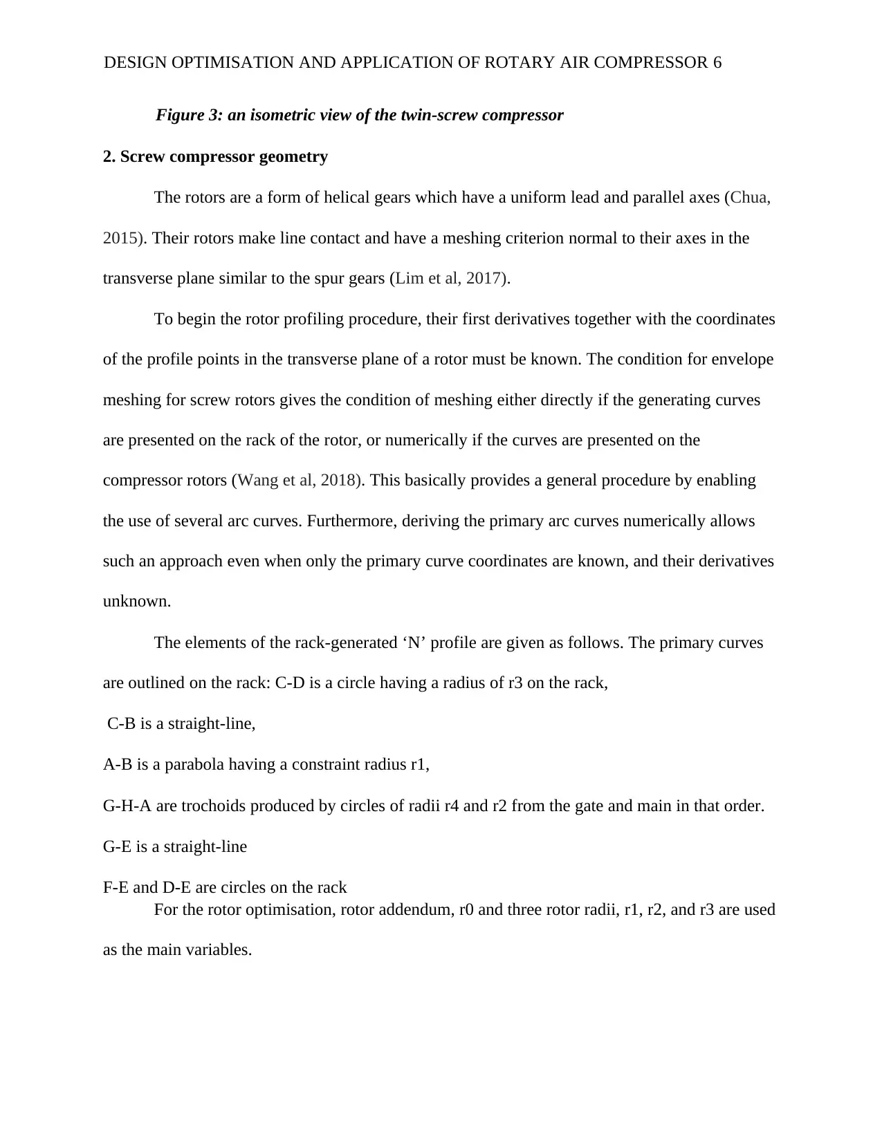
Figure 3: an isometric view of the twin-screw compressor
2. Screw compressor geometry
The rotors are a form of helical gears which have a uniform lead and parallel axes (Chua,
2015). Their rotors make line contact and have a meshing criterion normal to their axes in the
transverse plane similar to the spur gears (Lim et al, 2017).
To begin the rotor profiling procedure, their first derivatives together with the coordinates
of the profile points in the transverse plane of a rotor must be known. The condition for envelope
meshing for screw rotors gives the condition of meshing either directly if the generating curves
are presented on the rack of the rotor, or numerically if the curves are presented on the
compressor rotors (Wang et al, 2018). This basically provides a general procedure by enabling
the use of several arc curves. Furthermore, deriving the primary arc curves numerically allows
such an approach even when only the primary curve coordinates are known, and their derivatives
unknown.
The elements of the rack-generated ‘N’ profile are given as follows. The primary curves
are outlined on the rack: C-D is a circle having a radius of r3 on the rack,
C-B is a straight-line,
A-B is a parabola having a constraint radius r1,
G-H-A are trochoids produced by circles of radii r4 and r2 from the gate and main in that order.
G-E is a straight-line
F-E and D-E are circles on the rack
For the rotor optimisation, rotor addendum, r0 and three rotor radii, r1, r2, and r3 are used
as the main variables.
DESIGN OPTIMISATION AND APPLICATION OF ROTARY AIR COMPRESSOR 6
⊘ This is a preview!⊘
Do you want full access?
Subscribe today to unlock all pages.
Trusted by 1+ million students worldwide
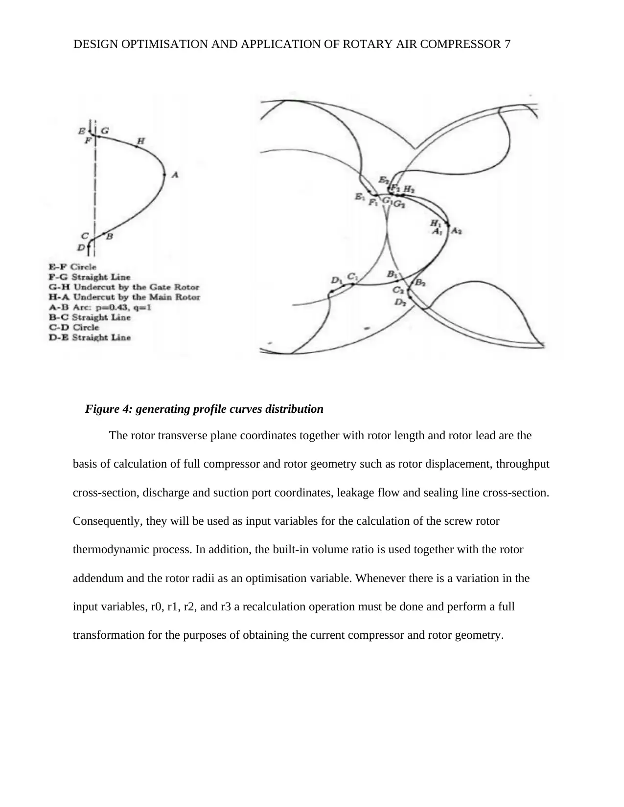
Figure 4: generating profile curves distribution
The rotor transverse plane coordinates together with rotor length and rotor lead are the
basis of calculation of full compressor and rotor geometry such as rotor displacement, throughput
cross-section, discharge and suction port coordinates, leakage flow and sealing line cross-section.
Consequently, they will be used as input variables for the calculation of the screw rotor
thermodynamic process. In addition, the built-in volume ratio is used together with the rotor
addendum and the rotor radii as an optimisation variable. Whenever there is a variation in the
input variables, r0, r1, r2, and r3 a recalculation operation must be done and perform a full
transformation for the purposes of obtaining the current compressor and rotor geometry.
DESIGN OPTIMISATION AND APPLICATION OF ROTARY AIR COMPRESSOR 7
Paraphrase This Document
Need a fresh take? Get an instant paraphrase of this document with our AI Paraphraser
3. Compressor thermodynamics in optimisation calculations
The thermodynamic and the flow processes algorithm applied has a mathematical model
that comprises of a set of equations describing all the science of the screw compressor such as
rotation angle and time, operating volume as well as mass and energy flow. These equations are
then subjected to the processes of suction, discharge, and compression within the machine.
This mathematical model has a feature that uses energy equation in a form that generates
internal energy rather than an enthalpy. This feature makes this model more convenient
computationally, more so when investigating real fluids properties. Moreover, internal energy
can only be presented as a function of specific volume and temperature only, thus pressure will
be computed directly thereafter. The internal energy and volume derive all the thermodynamic
and fluid properties remaining within the machine cycle then the computation is performed
through several cycles until the solution converges (MA et al, 2015).
The equation of the conversion of internal energy is given by;
Where 𝜃 is the main rotor rotation angle h=h(𝜃) is the specific enthalpy
𝘮 =𝘮(q) is the mass flowrate p=p(𝜃) is the fluid pressure in the control
volume of the working chamber
Q=Q(q) is the transfer of heat between the surrounding of compressor and fluid
V=V(q) is the compressor working chamber control volume
DESIGN OPTIMISATION AND APPLICATION OF ROTARY AIR COMPRESSOR 8
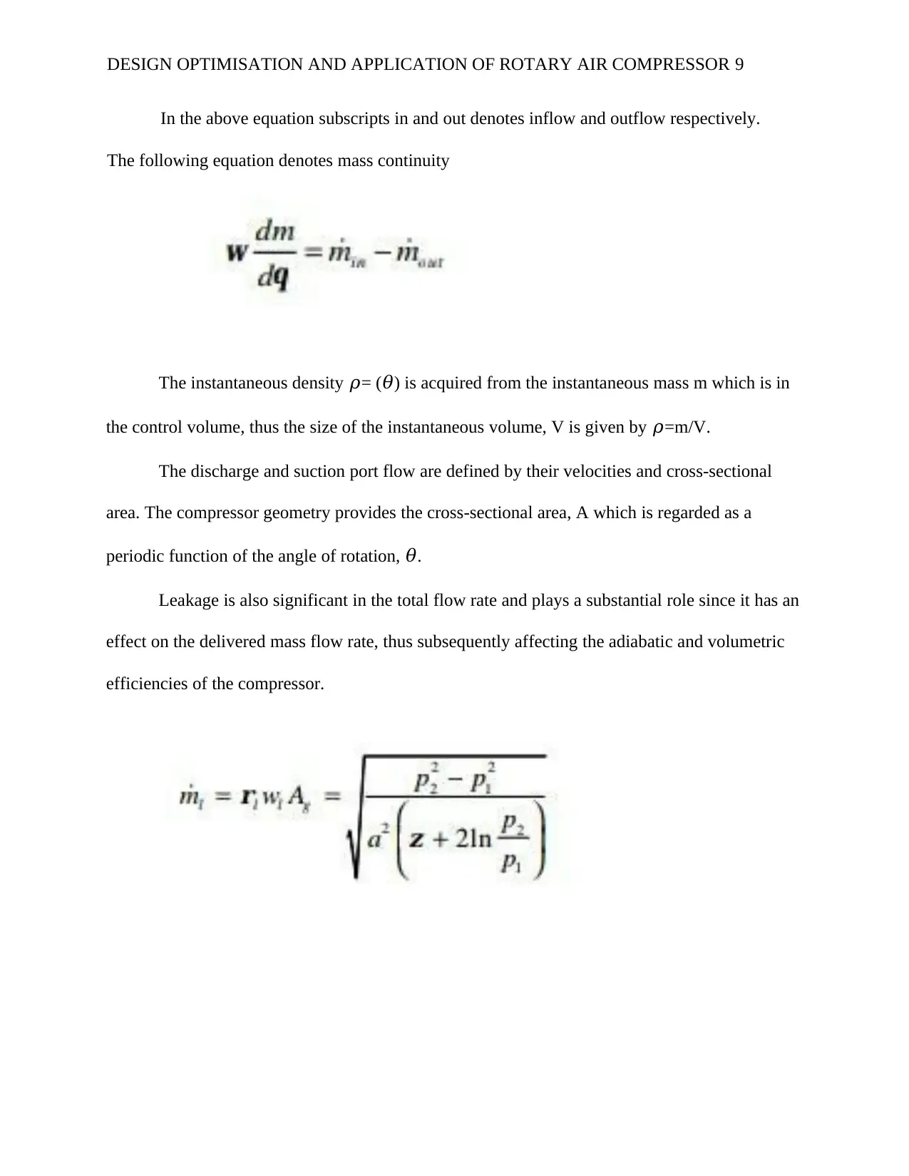
In the above equation subscripts in and out denotes inflow and outflow respectively.
The following equation denotes mass continuity
The instantaneous density 𝜌= (𝜃) is acquired from the instantaneous mass m which is in
the control volume, thus the size of the instantaneous volume, V is given by 𝜌=m/V.
The discharge and suction port flow are defined by their velocities and cross-sectional
area. The compressor geometry provides the cross-sectional area, A which is regarded as a
periodic function of the angle of rotation, 𝜃.
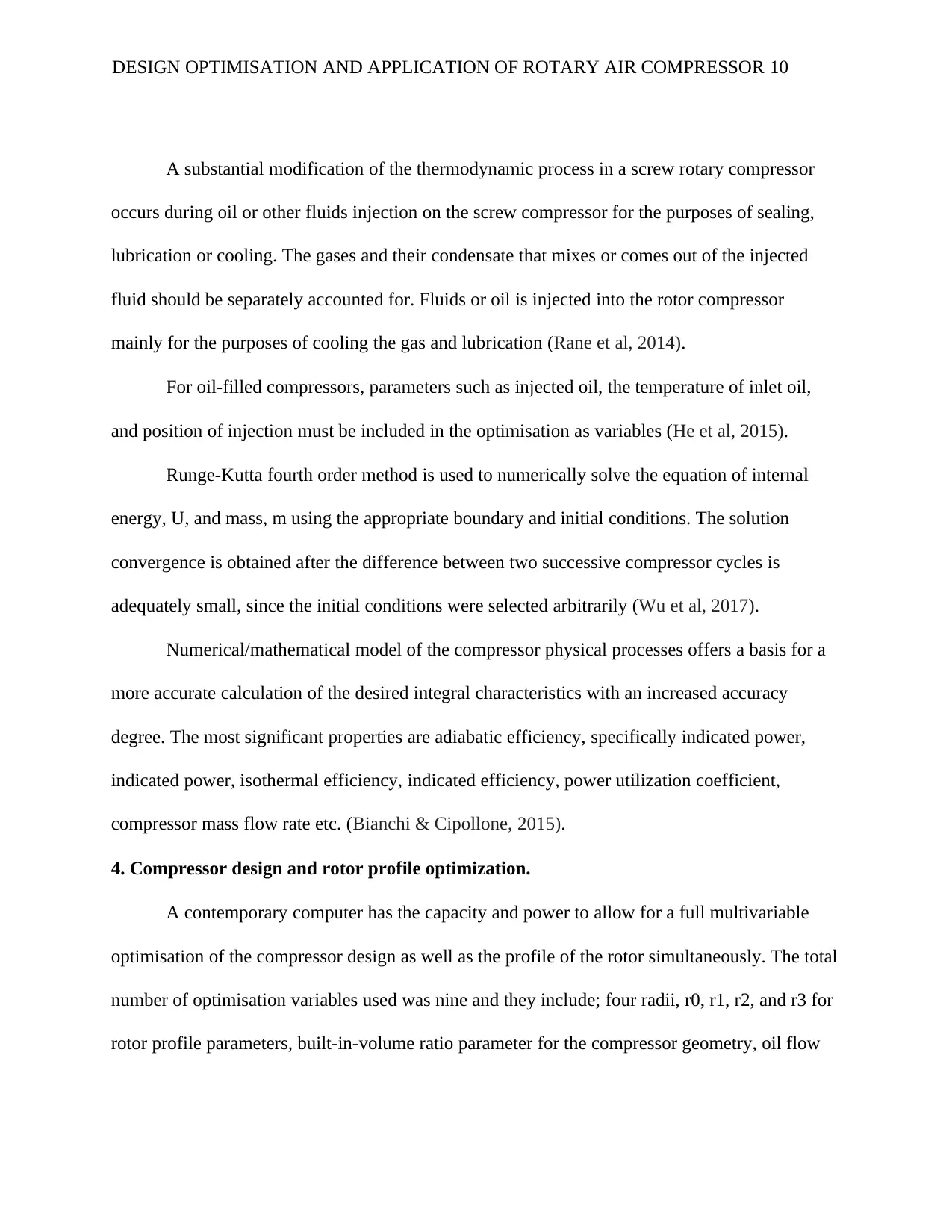
Leakage is also significant in the total flow rate and plays a substantial role since it has an
effect on the delivered mass flow rate, thus subsequently affecting the adiabatic and volumetric
efficiencies of the compressor.
DESIGN OPTIMISATION AND APPLICATION OF ROTARY AIR COMPRESSOR 9
The following equation denotes mass continuity
The instantaneous density 𝜌= (𝜃) is acquired from the instantaneous mass m which is in
the control volume, thus the size of the instantaneous volume, V is given by 𝜌=m/V.
The discharge and suction port flow are defined by their velocities and cross-sectional
area. The compressor geometry provides the cross-sectional area, A which is regarded as a
periodic function of the angle of rotation, 𝜃.
Leakage is also significant in the total flow rate and plays a substantial role since it has an
effect on the delivered mass flow rate, thus subsequently affecting the adiabatic and volumetric
efficiencies of the compressor.
DESIGN OPTIMISATION AND APPLICATION OF ROTARY AIR COMPRESSOR 9
⊘ This is a preview!⊘
Do you want full access?
Subscribe today to unlock all pages.
Trusted by 1+ million students worldwide
A substantial modification of the thermodynamic process in a screw rotary compressor
occurs during oil or other fluids injection on the screw compressor for the purposes of sealing,
lubrication or cooling. The gases and their condensate that mixes or comes out of the injected
fluid should be separately accounted for. Fluids or oil is injected into the rotor compressor
mainly for the purposes of cooling the gas and lubrication (Rane et al, 2014).
For oil-filled compressors, parameters such as injected oil, the temperature of inlet oil,
and position of injection must be included in the optimisation as variables (He et al, 2015).
Runge-Kutta fourth order method is used to numerically solve the equation of internal
energy, U, and mass, m using the appropriate boundary and initial conditions. The solution
convergence is obtained after the difference between two successive compressor cycles is
adequately small, since the initial conditions were selected arbitrarily (Wu et al, 2017).
Numerical/mathematical model of the compressor physical processes offers a basis for a
more accurate calculation of the desired integral characteristics with an increased accuracy
degree. The most significant properties are adiabatic efficiency, specifically indicated power,
indicated power, isothermal efficiency, indicated efficiency, power utilization coefficient,
compressor mass flow rate etc. (Bianchi & Cipollone, 2015).
4. Compressor design and rotor profile optimization.
A contemporary computer has the capacity and power to allow for a full multivariable
optimisation of the compressor design as well as the profile of the rotor simultaneously. The total
number of optimisation variables used was nine and they include; four radii, r0, r1, r2, and r3 for
rotor profile parameters, built-in-volume ratio parameter for the compressor geometry, oil flow
DESIGN OPTIMISATION AND APPLICATION OF ROTARY AIR COMPRESSOR 10
Paraphrase This Document
Need a fresh take? Get an instant paraphrase of this document with our AI Paraphraser
and compressor speed which are operating variables and position of injection and temperature
which are oil optimisation parameters (Järvisalo et al, 2015).
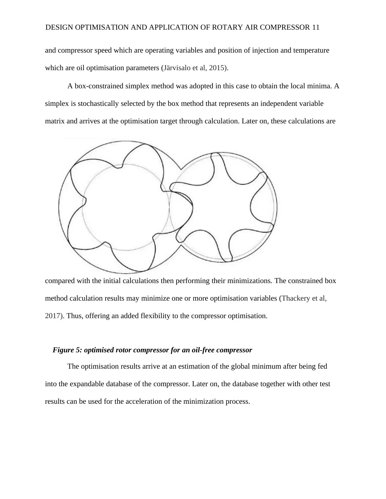
A box-constrained simplex method was adopted in this case to obtain the local minima. A
simplex is stochastically selected by the box method that represents an independent variable
matrix and arrives at the optimisation target through calculation. Later on, these calculations are
compared with the initial calculations then performing their minimizations. The constrained box
method calculation results may minimize one or more optimisation variables (Thackery et al,
2017). Thus, offering an added flexibility to the compressor optimisation.
Figure 5: optimised rotor compressor for an oil-free compressor
The optimisation results arrive at an estimation of the global minimum after being fed
into the expandable database of the compressor. Later on, the database together with other test
results can be used for the acceleration of the minimization process.
DESIGN OPTIMISATION AND APPLICATION OF ROTARY AIR COMPRESSOR 11
which are oil optimisation parameters (Järvisalo et al, 2015).
A box-constrained simplex method was adopted in this case to obtain the local minima. A
simplex is stochastically selected by the box method that represents an independent variable
matrix and arrives at the optimisation target through calculation. Later on, these calculations are
compared with the initial calculations then performing their minimizations. The constrained box
method calculation results may minimize one or more optimisation variables (Thackery et al,
2017). Thus, offering an added flexibility to the compressor optimisation.
Figure 5: optimised rotor compressor for an oil-free compressor
The optimisation results arrive at an estimation of the global minimum after being fed
into the expandable database of the compressor. Later on, the database together with other test
results can be used for the acceleration of the minimization process.
DESIGN OPTIMISATION AND APPLICATION OF ROTARY AIR COMPRESSOR 11
The dry air compressor exhibited 1-3 bar pressure for the discharge and suction pressure,
while the oil flooded compressor showed a pressure of 1-8 bar for the discharge and suction. The
condensation and evaporation temperatures were 40 and 5 degrees Celsius respectively for R-
134A. All the compressors had their male rotor outer diameters and centre distance kept constant
at 128.45 and 90 mm in that order.
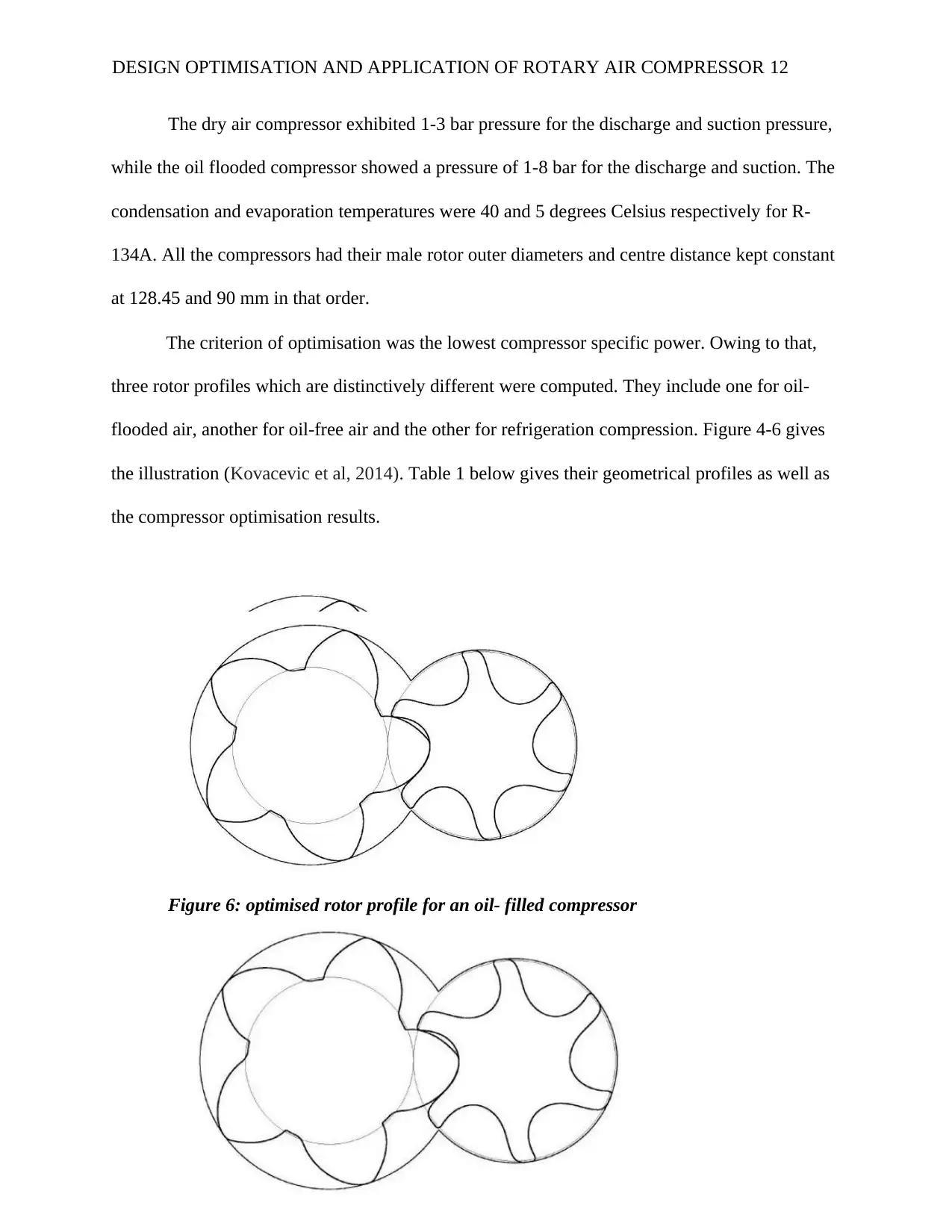
The criterion of optimisation was the lowest compressor specific power. Owing to that,
three rotor profiles which are distinctively different were computed. They include one for oil-
flooded air, another for oil-free air and the other for refrigeration compression. Figure 4-6 gives
the illustration (Kovacevic et al, 2014). Table 1 below gives their geometrical profiles as well as
the compressor optimisation results.
Figure 6: optimised rotor profile for an oil- filled compressor
DESIGN OPTIMISATION AND APPLICATION OF ROTARY AIR COMPRESSOR 12
while the oil flooded compressor showed a pressure of 1-8 bar for the discharge and suction. The
condensation and evaporation temperatures were 40 and 5 degrees Celsius respectively for R-
134A. All the compressors had their male rotor outer diameters and centre distance kept constant
at 128.45 and 90 mm in that order.
The criterion of optimisation was the lowest compressor specific power. Owing to that,
three rotor profiles which are distinctively different were computed. They include one for oil-
flooded air, another for oil-free air and the other for refrigeration compression. Figure 4-6 gives
the illustration (Kovacevic et al, 2014). Table 1 below gives their geometrical profiles as well as
the compressor optimisation results.
Figure 6: optimised rotor profile for an oil- filled compressor
DESIGN OPTIMISATION AND APPLICATION OF ROTARY AIR COMPRESSOR 12
⊘ This is a preview!⊘
Do you want full access?
Subscribe today to unlock all pages.
Trusted by 1+ million students worldwide
1 out of 18
Related Documents


Your All-in-One AI-Powered Toolkit for Academic Success.
+13062052269
info@desklib.com
Available 24*7 on WhatsApp / Email
![[object Object]](/_next/static/media/star-bottom.7253800d.svg)
Unlock your academic potential
Copyright © 2020–2026 A2Z Services. All Rights Reserved. Developed and managed by ZUCOL.