Three Point Bending and Shaft Design
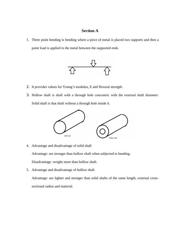
Analyzing the behavior of a simply supported beam under a three-point-bending test using analytical, numerical techniques, and CAD/CAE tools.
17 Pages2029 Words41 Views
Added on 2023-01-06
About This Document
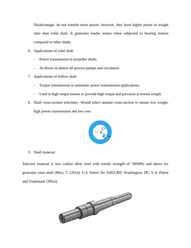
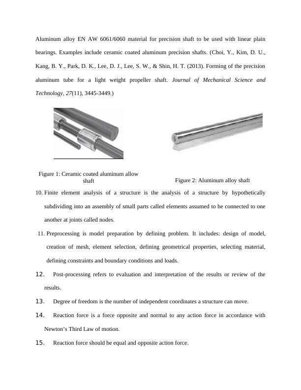
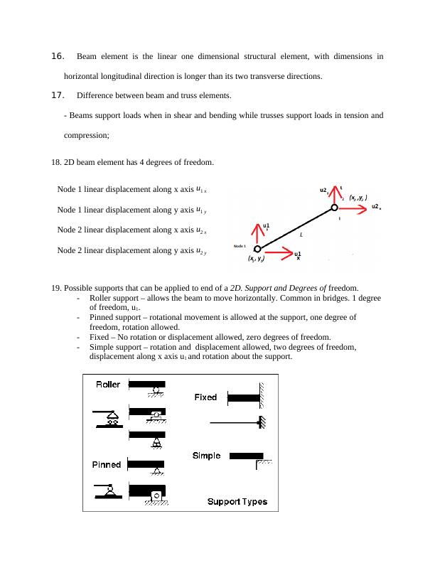
This document discusses three point bending and shaft design. It covers the advantages and disadvantages of solid and hollow shafts, applications of solid and hollow shafts, and the selection of shaft cross-section and material. It also explains the concept of finite element analysis, preprocessing, and post-processing. The document includes calculations for shear force, bending moment, and deflection in a hollow beam.
Three Point Bending and Shaft Design
Analyzing the behavior of a simply supported beam under a three-point-bending test using analytical, numerical techniques, and CAD/CAE tools.
Added on 2023-01-06
ShareRelated Documents
End of preview
Want to access all the pages? Upload your documents or become a member.