Power is directly proportional
VerifiedAdded on 2022/09/09
|9
|1632
|19
AI Summary
Contribute Materials
Your contribution can guide someone’s learning journey. Share your
documents today.
Section A
1. Power is directly proportional to V2, so if the voltage of a transmission line is double
power is expected to be increased by 4 times.
2. The formula for per unit impedance Zpu = ZΩ * (MVA)base / (KV)2base
3. Characteristic impedance is independent of the transmission line’s length.
4. The formula for voltage regulation of medium transmission line is (Vs - Vr) / Vr * 100
5. Protections schemes to be employed on transmission line are distance, earth fault and
overcurrent protection.
Section B
1. S = √ 3 * VL-L * IL…………1
S = 500MVA
VL-L = 345kV
From equation 1
IL = S / √ 3 * VL-L
= (500 * 106) / √ 3 * (345 * 103)
= 836.74A
a) Load impedance per phase
Impedance per phase, Z = Vph / Iph
For delta connection phase voltage is equal to line voltage and line current is √ 3 * phase
current, thus, VRY = 345 < 00 kV
IRY = 836.74 / √ 3
= 483< -300 A
Impedance in RY phase, ZRY = VRY / IRY
= 345< 0 kV / 483< -300 A
= 237.67<30 Ω
Assuming a balanced load, Zry=Zyb = Zrb = 236.67<30 Ω
b) Load current and phase current
Phase currents
IRY = 483 < -30 A
IYB = 483 < -150 A
Secure Best Marks with AI Grader
Need help grading? Try our AI Grader for instant feedback on your assignments.
IBR = 483 < 90 A
Load current is equal to the line current which is equal to 1449.275<-30 A
c) Real and reactive power per phase
Real power, p = Vph * Iph * p.f
= 345 * 483 * 0.866
= 144.305 kW
Reactive power, Q = Vph * Iph * sin ∅
= 345 * 483 * sin 30
= 83.318kVar
d) Total real and reactive power by load
Total real power = 3 * real power per phase
= 3 * 144.305
= 432.915 kW.
Total reactive power = 3 * reactive power per phase
= 3 * 83.318
= 250 kVar
2. The main function of protection relay is to detect existence of a fault, its location and the
type of fault. Protection relay plays a role in tripping the circuit by operating the circuit
breaker, thus isolating the faulty section or system from the healthier one. This help in
reducing damage to equipment, animals and also human beings. The basic requirement of
a protection relay is to isolate the faulty system in the shortest time possible when a short
circuit is detected or when abnormal behavior is experienced.
Relays to be used in transformer protection are differential relay, Over-flux relay,
Buchholz relay, winding temperature trip relays, oil temperature trip and many more.
Relays to be used in transmission line protection are inverse time relays with definite
minimum time (IDMT), switched distance scheme. And finally, in busbars, overcurrent
relays, numerical relays, differential relays are widely used.
3. Ia = 10 < 0
Ib = 0
Ic = 10<120
a) Positive sequence current
I1 = 1/3 (Ia + aIb + a2Ic) where a = 1<1200 and a2 = 1<2400
= 1/3 (10 < 0 + 0 + 1<2400(10<120))
= 6.667<0
b) Negative sequence current
I2 = 1/3 (Ia + a2 * Ib + aIc) where a = 1<1200 and a2 = 1<2400
= 1/3 (10<0 + 0 + 1<120(10<120))
= 3.33<-60
c) Zero sequence current
Ia0 = Ib0 = Ic0 = 1/3 (Ia + Ib + Ic)
= 1/3 (10<00 + 0 + 10<1200)
= 3.33<60
d) The neutral current
In = Ia + Ib + Ic
= 10 <0 + 0 + 10<120
= 10<600 A
Section C
1. Industrial motors
a) The line current
Power of the load = 500kW
Power factor, cos ∅ = 0.6, thus ∅ = cos-1(0.6) = 530
P = √ 3 * VL * IL * cos ∅
IL = P / (√ 3 * VL * cos ∅)
=500kW / ( √ 3 * 2300 * 0.6)
= 209.2 A
b) Voltage at the sending end
From ohms law
Voltage at the sending end, Vs = IL * (Zeq) + VR (voltage at the receiving end)
= 209.2 * (0.25 + j0.75) + 2300
= 2357.53 < 3.80 V
c) Power, reactive power and voltampere at the sending end
Real power, P = √ 3 * VS * IL * cos ∅
= √ 3 * 2357.53 * 209.2 * 0.6
= 512.543 kW
Reactive power, Q = √ 3 * VS * IL * Sin ∅
= √ 3 * 2357.53 * 209.2 * Sin 53
= 682.225 kVar
Voltampere, S = √ 3 * VS * IL
=√ 3 * 2357.53 * 209.2
= 854.24kVA
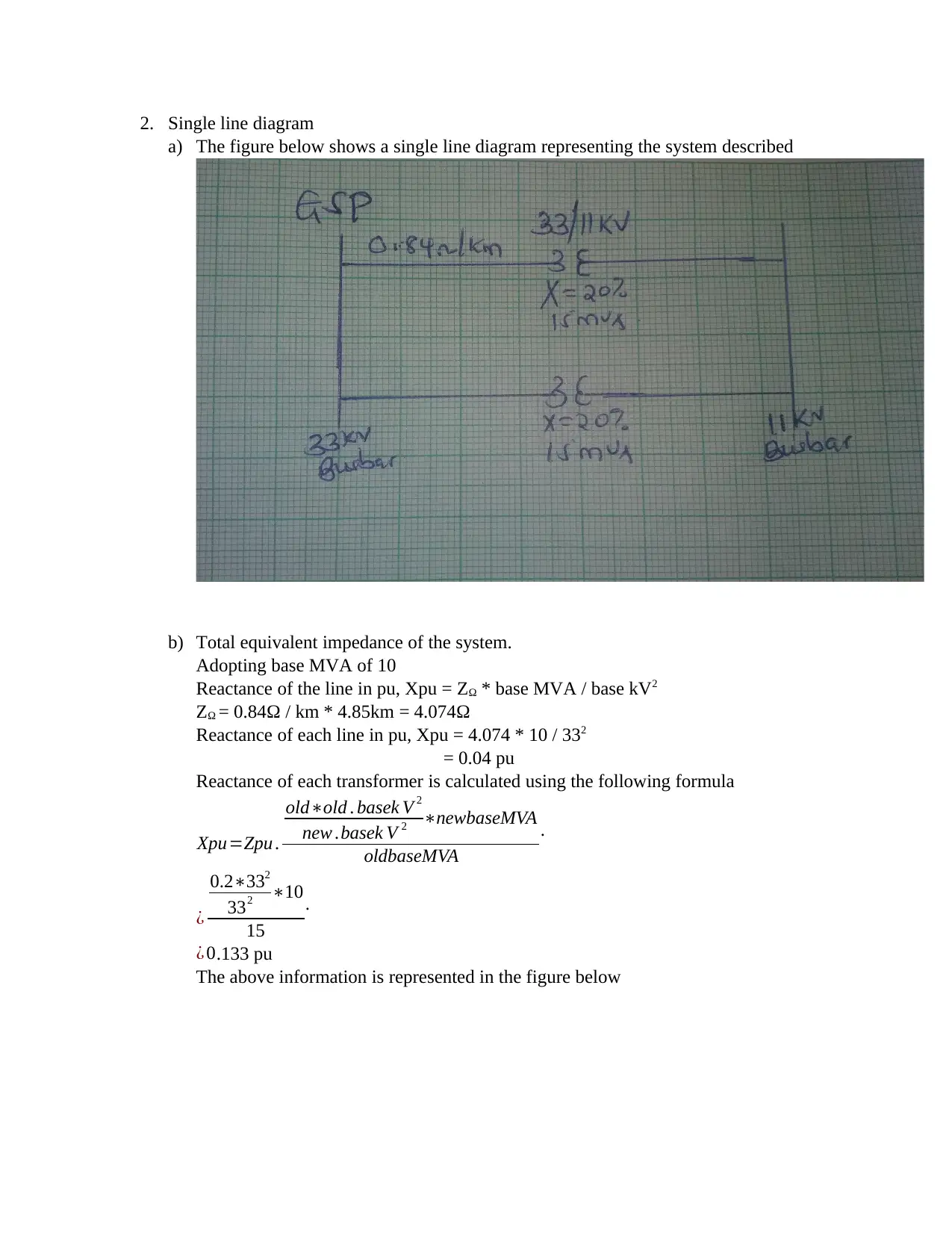
2. Single line diagram
a) The figure below shows a single line diagram representing the system described
b) Total equivalent impedance of the system.
Adopting base MVA of 10
Reactance of the line in pu, Xpu = ZΩ * base MVA / base kV2
ZΩ = 0.84Ω / km * 4.85km = 4.074Ω
Reactance of each line in pu, Xpu = 4.074 * 10 / 332
= 0.04 pu
Reactance of each transformer is calculated using the following formula
Xpu=Zpu .
old∗old . basek V 2
new .basek V 2 ∗newbaseMVA
oldbaseMVA
.
¿
0.2∗332
332 ∗10
15
.
¿ 0.133 pu
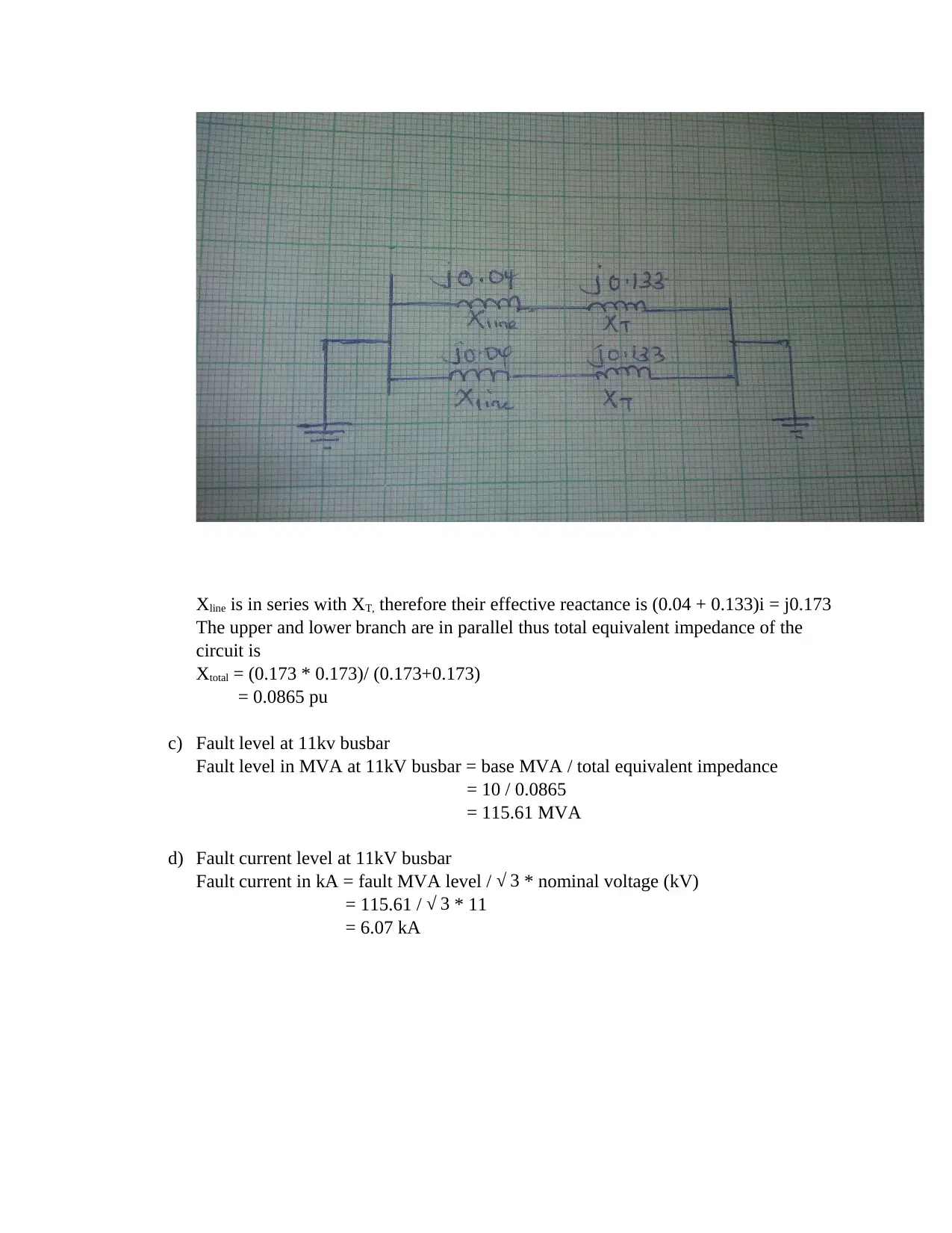
The above information is represented in the figure below
Secure Best Marks with AI Grader
Need help grading? Try our AI Grader for instant feedback on your assignments.
Xline is in series with XT, therefore their effective reactance is (0.04 + 0.133)i = j0.173
The upper and lower branch are in parallel thus total equivalent impedance of the
circuit is
Xtotal = (0.173 * 0.173)/ (0.173+0.173)
= 0.0865 pu
c) Fault level at 11kv busbar
Fault level in MVA at 11kV busbar = base MVA / total equivalent impedance
= 10 / 0.0865
= 115.61 MVA
d) Fault current level at 11kV busbar
Fault current in kA = fault MVA level / √ 3 * nominal voltage (kV)
= 115.61 / √ 3 * 11
= 6.07 kA
3. Single line to ground fault
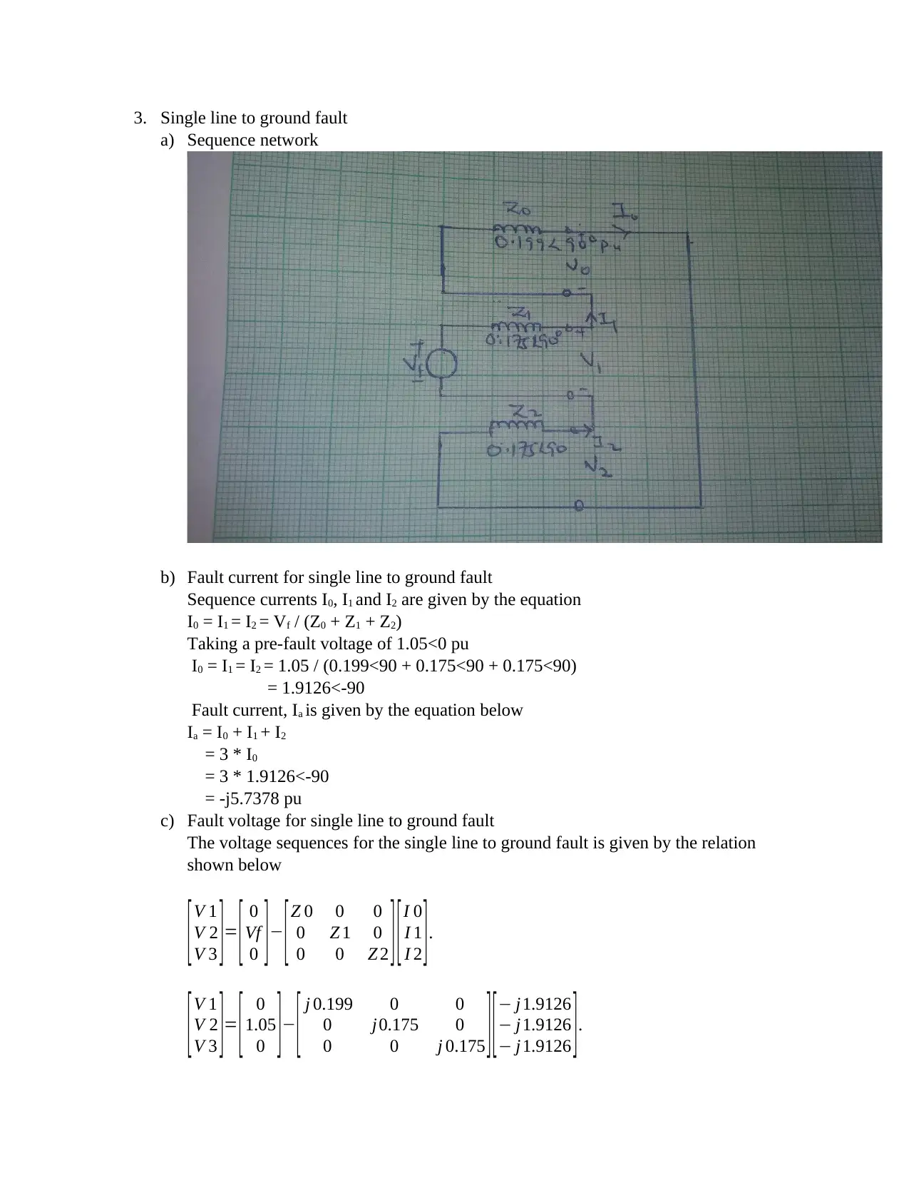
a) Sequence network
b) Fault current for single line to ground fault
Sequence currents I0, I1 and I2 are given by the equation
I0 = I1 = I2 = Vf / (Z0 + Z1 + Z2)
Taking a pre-fault voltage of 1.05<0 pu
I0 = I1 = I2 = 1.05 / (0.199<90 + 0.175<90 + 0.175<90)
= 1.9126<-90
Fault current, Ia is given by the equation below
Ia = I0 + I1 + I2
= 3 * I0
= 3 * 1.9126<-90
= -j5.7378 pu
c) Fault voltage for single line to ground fault
The voltage sequences for the single line to ground fault is given by the relation
shown below
[ V 1
V 2
V 3 ]= [ 0
Vf
0 ] − [ Z 0 0 0
0 Z 1 0
0 0 Z 2 ][ I 0
I 1
I 2 ].
[V 1
V 2
V 3 ]= [ 0
1.05
0 ]− [ j 0.199 0 0
0 j0.175 0
0 0 j 0.175 ][− j 1.9126
− j 1.9126
− j 1.9126 ].
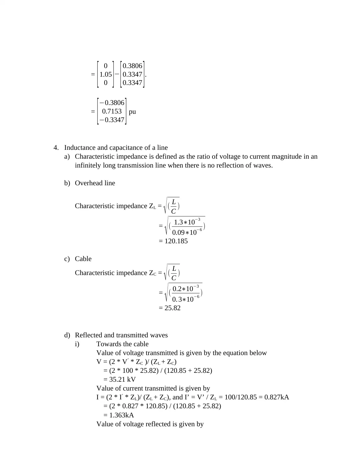
= [ 0
1.05
0 ]− [0.3806
0.3347
0.3347 ].
= [ −0.3806
0.7153
−0.3347 ] pu
4. Inductance and capacitance of a line
a) Characteristic impedance is defined as the ratio of voltage to current magnitude in an
infinitely long transmission line when there is no reflection of waves.
b) Overhead line
Characteristic impedance ZL = √ ( L
C )
= √( 1.3∗10−3
0.09∗10−6 )
= 120.185
c) Cable
Characteristic impedance ZC = √( L
C )
= √( 0.2∗10−3
0. 3∗10−6 )
= 25.82
d) Reflected and transmitted waves
i) Towards the cable
Value of voltage transmitted is given by the equation below
V = (2 * V’ * ZC )/ (ZL + ZC)
= (2 * 100 * 25.82) / (120.85 + 25.82)
= 35.21 kV
Value of current transmitted is given by
I = (2 * I’ * ZL)/ (ZL + ZC), and I’ = V’ / ZL = 100/120.85 = 0.827kA
= (2 * 0.827 * 120.85) / (120.85 + 25.82)
= 1.363kA
Value of voltage reflected is given by
Paraphrase This Document
Need a fresh take? Get an instant paraphrase of this document with our AI Paraphraser
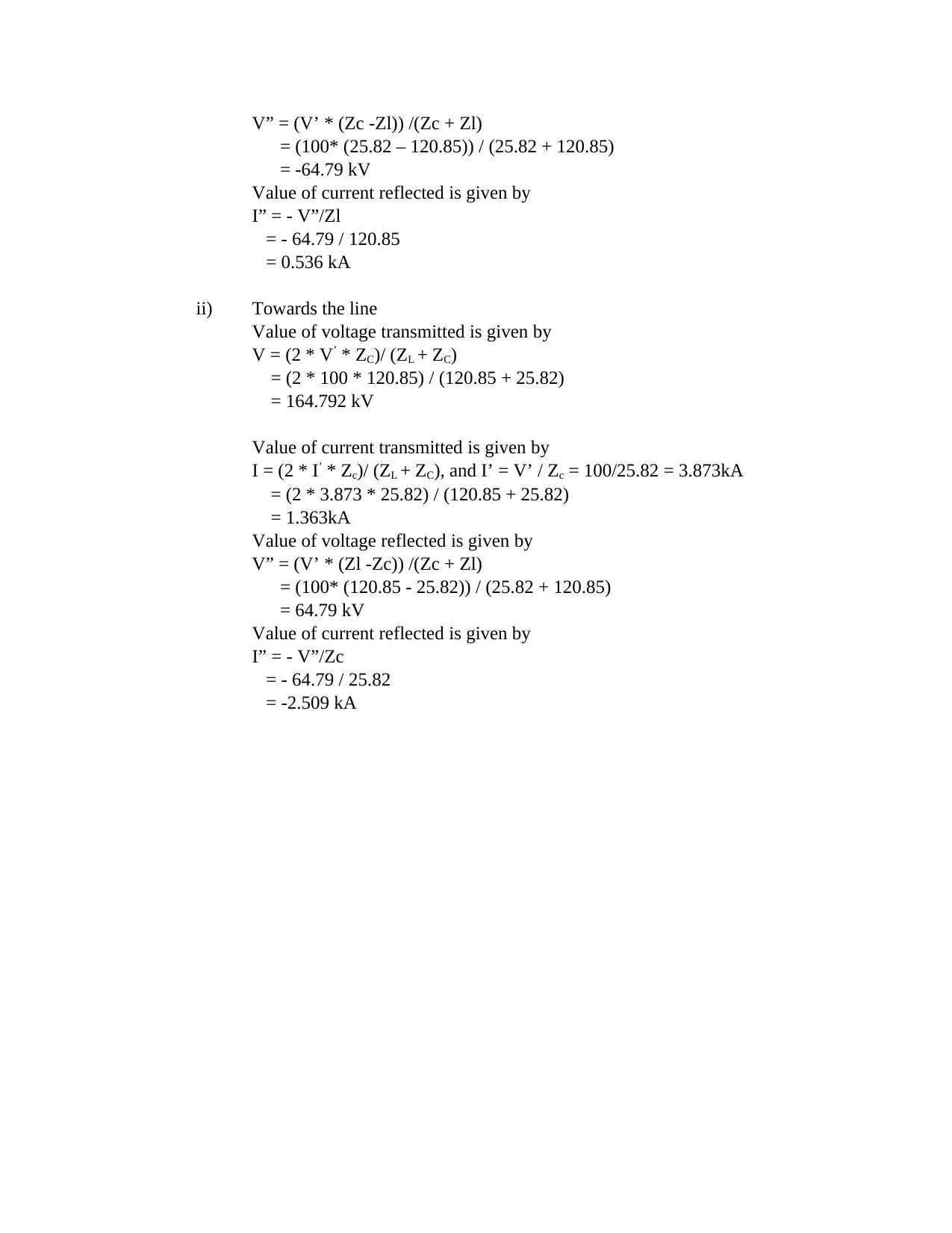
V” = (V’ * (Zc -Zl)) /(Zc + Zl)
= (100* (25.82 – 120.85)) / (25.82 + 120.85)
= -64.79 kV
Value of current reflected is given by
I” = - V”/Zl
= - 64.79 / 120.85
= 0.536 kA
ii) Towards the line
Value of voltage transmitted is given by
V = (2 * V’ * ZC)/ (ZL + ZC)
= (2 * 100 * 120.85) / (120.85 + 25.82)
= 164.792 kV
Value of current transmitted is given by
I = (2 * I’ * Zc)/ (ZL + ZC), and I’ = V’ / Zc = 100/25.82 = 3.873kA
= (2 * 3.873 * 25.82) / (120.85 + 25.82)
= 1.363kA
Value of voltage reflected is given by
V” = (V’ * (Zl -Zc)) /(Zc + Zl)
= (100* (120.85 - 25.82)) / (25.82 + 120.85)
= 64.79 kV
Value of current reflected is given by
I” = - V”/Zc
= - 64.79 / 25.82
= -2.509 kA
REFERENCE LIST
Blackburn, J.L. (2017). Symmetrical components for power systems engineering. CRC Press.
Electrical4u. (2019). Types of electrical protection relays or protection relays. Retrieved from
www.electrical4u.com/types-of-electrical-protection-relays-or-protective-relays/ accessed
on December 14, 2019.
Nasar, S.A. and Trutt, F.C. (2018). Electric power systems. Routledge.
1 out of 9
Related Documents
Your All-in-One AI-Powered Toolkit for Academic Success.
+13062052269
info@desklib.com
Available 24*7 on WhatsApp / Email
Unlock your academic potential
© 2024 | Zucol Services PVT LTD | All rights reserved.