Short Dipole Antenna Design, Analysis, and MATLAB Simulation Report
VerifiedAdded on 2023/06/11
|5
|1016
|212
Report
AI Summary
This report provides a comprehensive overview of the design and simulation of a short dipole antenna using MATLAB. It begins with an introduction to short dipole antennas, highlighting their characteristics and applications. The report then details the design process, including the calculations for wav...
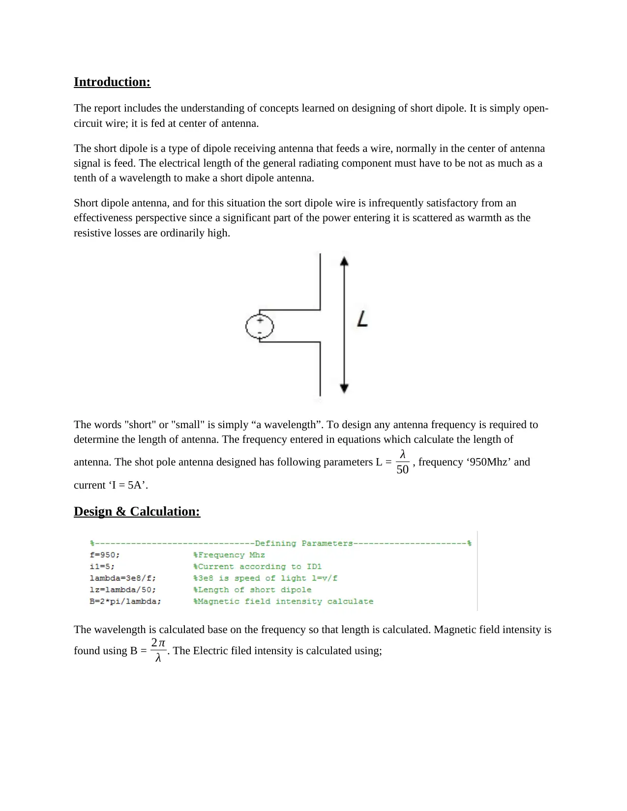
Introduction:
The report includes the understanding of concepts learned on designing of short dipole. It is simply open-
circuit wire; it is fed at center of antenna.
The short dipole is a type of dipole receiving antenna that feeds a wire, normally in the center of antenna
signal is feed. The electrical length of the general radiating component must have to be not as much as a
tenth of a wavelength to make a short dipole antenna.
Short dipole antenna, and for this situation the sort dipole wire is infrequently satisfactory from an
effectiveness perspective since a significant part of the power entering it is scattered as warmth as the
resistive losses are ordinarily high.
The words "short" or "small" is simply “a wavelength”. To design any antenna frequency is required to
determine the length of antenna. The frequency entered in equations which calculate the length of
antenna. The shot pole antenna designed has following parameters L = λ
50 , frequency ‘950Mhz’ and
current ‘I = 5A’.
Design & Calculation:
The wavelength is calculated base on the frequency so that length is calculated. Magnetic field intensity is
found using B = 2 π
λ . The Electric filed intensity is calculated using;
Paraphrase This Document
Need a fresh take? Get an instant paraphrase of this document with our AI Paraphraser
It is implanted on Matlab base on angle and step size shown below.
The Radiated power is found using following formula
Result & Analysis:
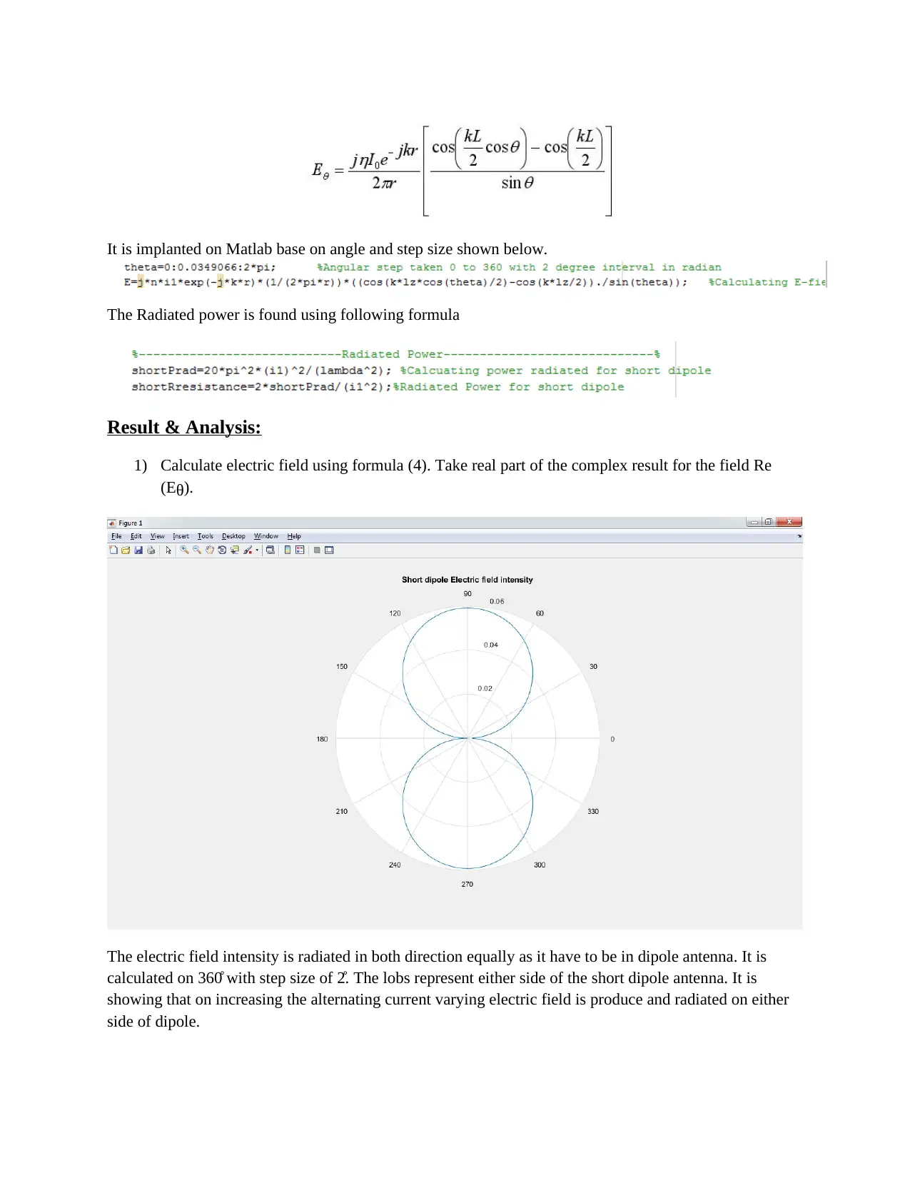
1) Calculate electric field using formula (4). Take real part of the complex result for the field Re
(Eθ).
The electric field intensity is radiated in both direction equally as it have to be in dipole antenna. It is
calculated on 360̊ with step size of 2̊. The lobs represent either side of the short dipole antenna. It is
showing that on increasing the alternating current varying electric field is produce and radiated on either
side of dipole.
The Radiated power is found using following formula
Result & Analysis:
1) Calculate electric field using formula (4). Take real part of the complex result for the field Re
(Eθ).
The electric field intensity is radiated in both direction equally as it have to be in dipole antenna. It is
calculated on 360̊ with step size of 2̊. The lobs represent either side of the short dipole antenna. It is
showing that on increasing the alternating current varying electric field is produce and radiated on either
side of dipole.
2) Calculate radiated power S for each angle direction θ, normalize the power by dividing all values
by maximum power.
The total radiated power obtain was the sum of power radiated with every angle from 0 to 360̊. It can be
seen as the short dipole shows power radiated as same as hertzian dipole of much smaller length i.e ≤ 50.
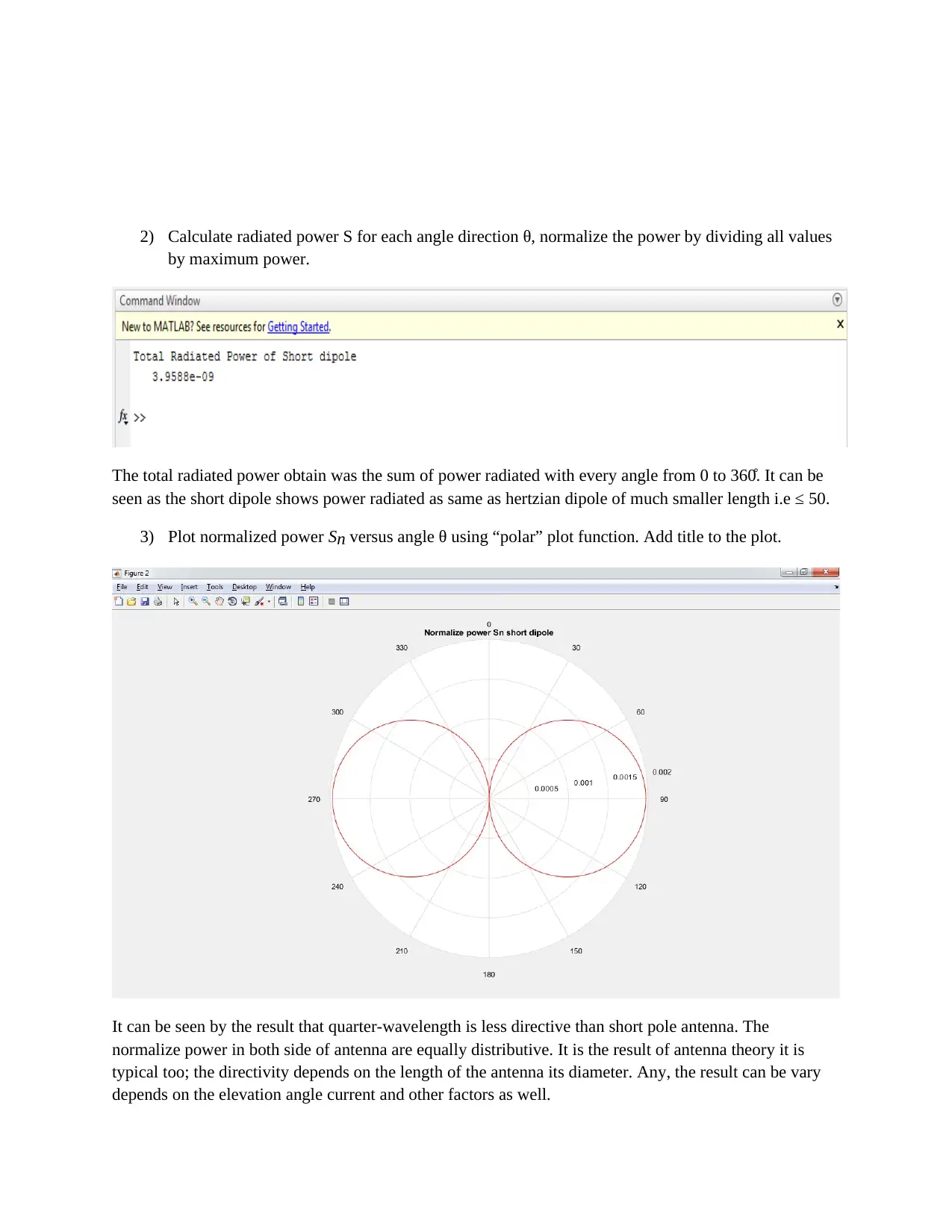
3) Plot normalized power Sn versus angle θ using “polar” plot function. Add title to the plot.
It can be seen by the result that quarter-wavelength is less directive than short pole antenna. The
normalize power in both side of antenna are equally distributive. It is the result of antenna theory it is
typical too; the directivity depends on the length of the antenna its diameter. Any, the result can be vary
depends on the elevation angle current and other factors as well.
by maximum power.
The total radiated power obtain was the sum of power radiated with every angle from 0 to 360̊. It can be
seen as the short dipole shows power radiated as same as hertzian dipole of much smaller length i.e ≤ 50.
3) Plot normalized power Sn versus angle θ using “polar” plot function. Add title to the plot.
It can be seen by the result that quarter-wavelength is less directive than short pole antenna. The
normalize power in both side of antenna are equally distributive. It is the result of antenna theory it is
typical too; the directivity depends on the length of the antenna its diameter. Any, the result can be vary
depends on the elevation angle current and other factors as well.
⊘ This is a preview!⊘
Do you want full access?
Subscribe today to unlock all pages.
Trusted by 1+ million students worldwide

Appendix:
clc
clear all
close all
%-------------------------------Defining Parameters----------------------%
f=950; %Frequency Mhz
i1=5; %Current according to ID1
lambda=3e8/f; %3e8 is speed of light l=v/f
lz=lambda/50; %Length of short dipole
B=2*pi/lambda; %Magnetic field intensity calculate
%---------------------Electric field intensity---------------------------%
%-----E=jnIoe^(-jkr)[Cos(KL/2*cos(theta)-Cos(KL/2)/Sin(theta))]/2pir-----%
figure(1)
n=377; %n=377
r=10; %---------
k=(2*pi)/lambda; %given formula
theta=0:0.0349066:2*pi; %Angular step taken 0 to 360 with 2 degree
interval in radian
E=j*n*i1*exp(-j*k*r)*(1/(2*pi*r))*((cos(k*lz*cos(theta)/2)-cos(k*lz/2))./
sin(theta)); %Calculating E-field
polar(theta, abs(E)) %Ploting Electric field in polar
title('Short dipole Electric field intensity')
%----------------------------Radiated Power-----------------------------%
shortPrad=20*pi^2*(i1)^2/(lambda^2); %Calcuating power radiated for short
dipole
shortpower=2*shortPrad/(i1^2);%Radiated Power for short dipole
disp('Total Radiated Power of Short dipole')
disp(shortpower)
%--------------------Normalize Power Sn of Short dipole-----------------%
figure (2) %Calcuting for short
x=0:0.0349066:2*pi; %Angular of steps 2 degrees to radian
A=cos(B.*lz/2); %Changing length according to short dipole
p=cos(cos(x).*B.*lz/2)-A; %For normalize power calculation -----------
m=-p./sin(x);
polar(x,m,'r')
hold on
polar(x,-m,'r')
view(-270,-90)
title('Normalize power Sn short dipole')%---------------
Paraphrase This Document
Need a fresh take? Get an instant paraphrase of this document with our AI Paraphraser

Reference:
[1] http://www.antenna-theory.com/antennas/shortdipole.php
[2] http://www.rfwireless-world.com/calculators/Dipole-Antenna-Calculator.html
[3] http://farside.ph.utexas.edu/teaching/em/lectures/node94.html
[4] http://slideplayer.com/slide/5346835/#
[5] http://www.raymaps.com/index.php/dipole-antenna/
[6] http://www.antenna-theory.com/antennas/dipole.php
1 out of 5
Your All-in-One AI-Powered Toolkit for Academic Success.
+13062052269
info@desklib.com
Available 24*7 on WhatsApp / Email
![[object Object]](/_next/static/media/star-bottom.7253800d.svg)
Unlock your academic potential
© 2024 | Zucol Services PVT LTD | All rights reserved.