Signal Processing
VerifiedAdded on 2023/04/11
|26
|1929
|326
AI Summary
This document discusses various aspects of signal processing, including double-sideband AM, DSB-SC modulation, and suppressed-sideband AM. It provides MATLAB code and plots for each topic.
Contribute Materials
Your contribution can guide someone’s learning journey. Share your
documents today.
Running head: SIGNAL PROCESSING
SIGNAL PROCESSING
Name of the Student
Name of the University
Author Note
SIGNAL PROCESSING
Name of the Student
Name of the University
Author Note
Secure Best Marks with AI Grader
Need help grading? Try our AI Grader for instant feedback on your assignments.
1SIGNAL PROCESSING
Part I: Double-SideBand AM
Exercise 1: Standard AM
Given, modulated signal is
s(t) = Ac[1 + ka*m(t)]cos(2*π*fc*t)
The information bearing signal is
m(t) = sinc(2(t-2)) – sinc(2(t+2))
The carrier signal is c(t) = Ac*cos(2πfct), Ac = 1 is the amplitude of carrier and fc = 50 Hz is
the carrier frequency.
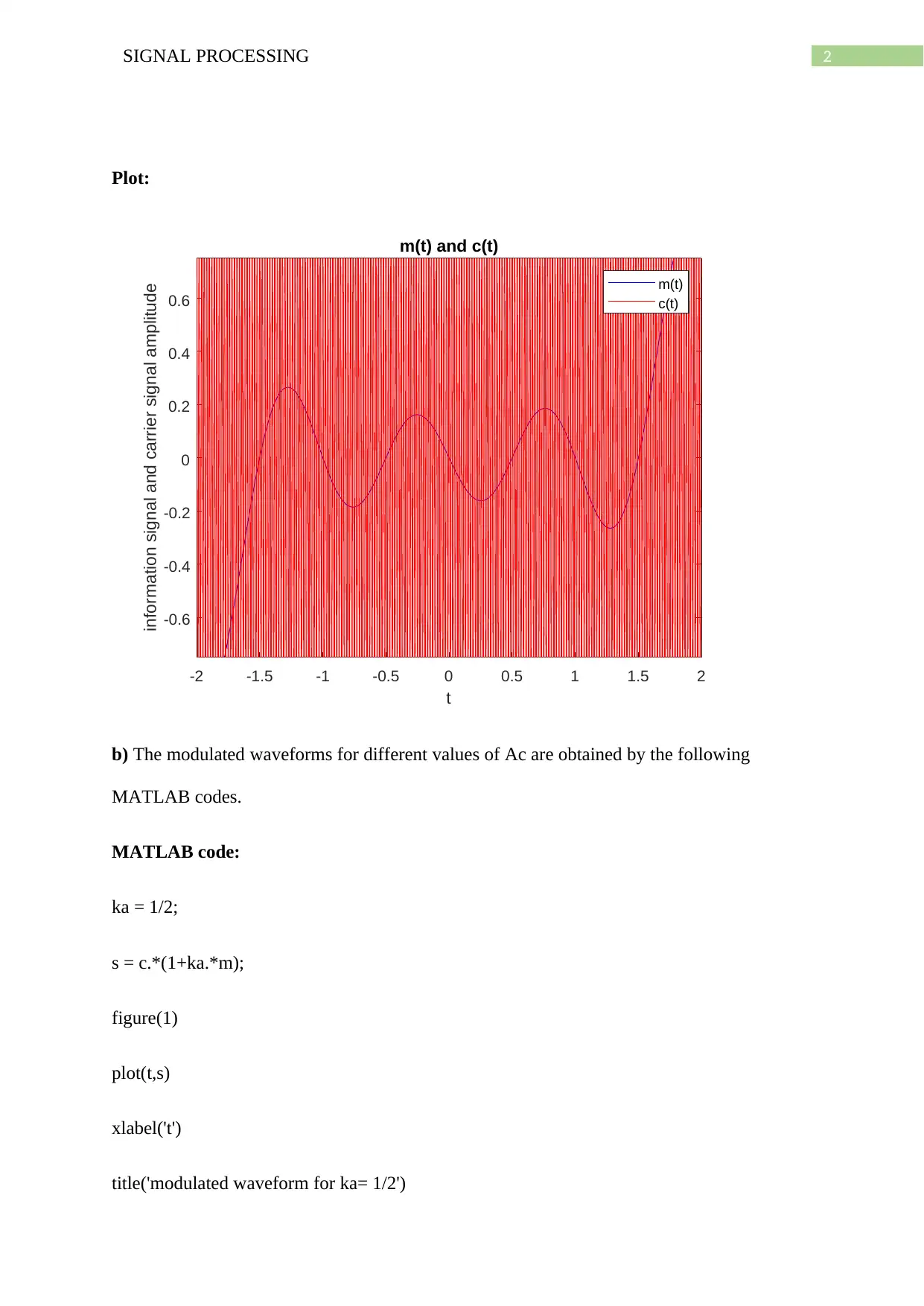
a) The plot of signal m(t) and carrier c(t) is given below.
MATLAB code:
t = -4:0.001:3.999;
Ac = 1; fc = 50;
m = sinc(2.*(t-2)) - sinc(2.*(t+2));
c = Ac*cos(2*pi*fc.*t);
plot(t,m,'b-',t,c,'r-')
title('m(t) and c(t)')
legend('m(t)','c(t)')
xlabel('t')
ylabel('information signal and carrier signal amplitude')
zoom(2)
2SIGNAL PROCESSING
Plot:
-2 -1.5 -1 -0.5 0 0.5 1 1.5 2
t
-0.6
-0.4
-0.2
0
0.2
0.4
0.6
information signal and carrier signal amplitude
m(t) and c(t)
m(t)
c(t)
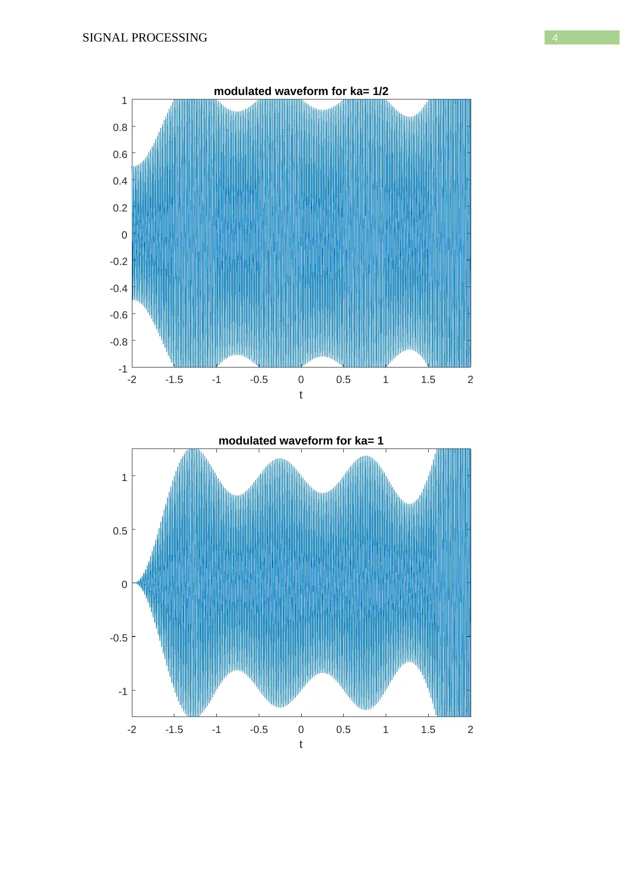
b) The modulated waveforms for different values of Ac are obtained by the following
MATLAB codes.
MATLAB code:
ka = 1/2;
s = c.*(1+ka.*m);
figure(1)
plot(t,s)
xlabel('t')
title('modulated waveform for ka= 1/2')
3SIGNAL PROCESSING
zoom(2)
ka = 1;
s = c.*(1+ka.*m);
figure(2)
plot(t,s)
xlabel('t')
title('modulated waveform for ka= 1')
zoom(2)
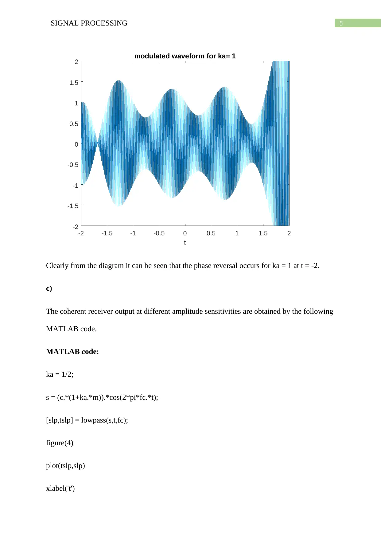
ka = 2;
s = c.*(1+ka.*m);
figure(3)
plot(t,s)
xlabel('t')
title('modulated waveform for ka= 1')
zoom(2)
Plots:
zoom(2)
ka = 1;
s = c.*(1+ka.*m);
figure(2)
plot(t,s)
xlabel('t')
title('modulated waveform for ka= 1')
zoom(2)
ka = 2;
s = c.*(1+ka.*m);
figure(3)
plot(t,s)
xlabel('t')
title('modulated waveform for ka= 1')
zoom(2)
Plots:
Secure Best Marks with AI Grader
Need help grading? Try our AI Grader for instant feedback on your assignments.
4SIGNAL PROCESSING
-2 -1.5 -1 -0.5 0 0.5 1 1.5 2
t
-1
-0.8
-0.6
-0.4
-0.2
0
0.2
0.4
0.6
0.8
1 modulated waveform for ka= 1/2
-2 -1.5 -1 -0.5 0 0.5 1 1.5 2
t
-1
-0.5
0
0.5
1
modulated waveform for ka= 1
-2 -1.5 -1 -0.5 0 0.5 1 1.5 2
t
-1
-0.8
-0.6
-0.4
-0.2
0
0.2
0.4
0.6
0.8
1 modulated waveform for ka= 1/2
-2 -1.5 -1 -0.5 0 0.5 1 1.5 2
t
-1
-0.5
0
0.5
1
modulated waveform for ka= 1
5SIGNAL PROCESSING
-2 -1.5 -1 -0.5 0 0.5 1 1.5 2
t
-2
-1.5
-1
-0.5
0
0.5
1
1.5
2 modulated waveform for ka= 1
Clearly from the diagram it can be seen that the phase reversal occurs for ka = 1 at t = -2.
c)
The coherent receiver output at different amplitude sensitivities are obtained by the following
MATLAB code.
MATLAB code:
ka = 1/2;
s = (c.*(1+ka.*m)).*cos(2*pi*fc.*t);
[slp,tslp] = lowpass(s,t,fc);
figure(4)
plot(tslp,slp)
xlabel('t')
6SIGNAL PROCESSING
hold on
plot(t,m)
legend('Recovered signal','Original signal')
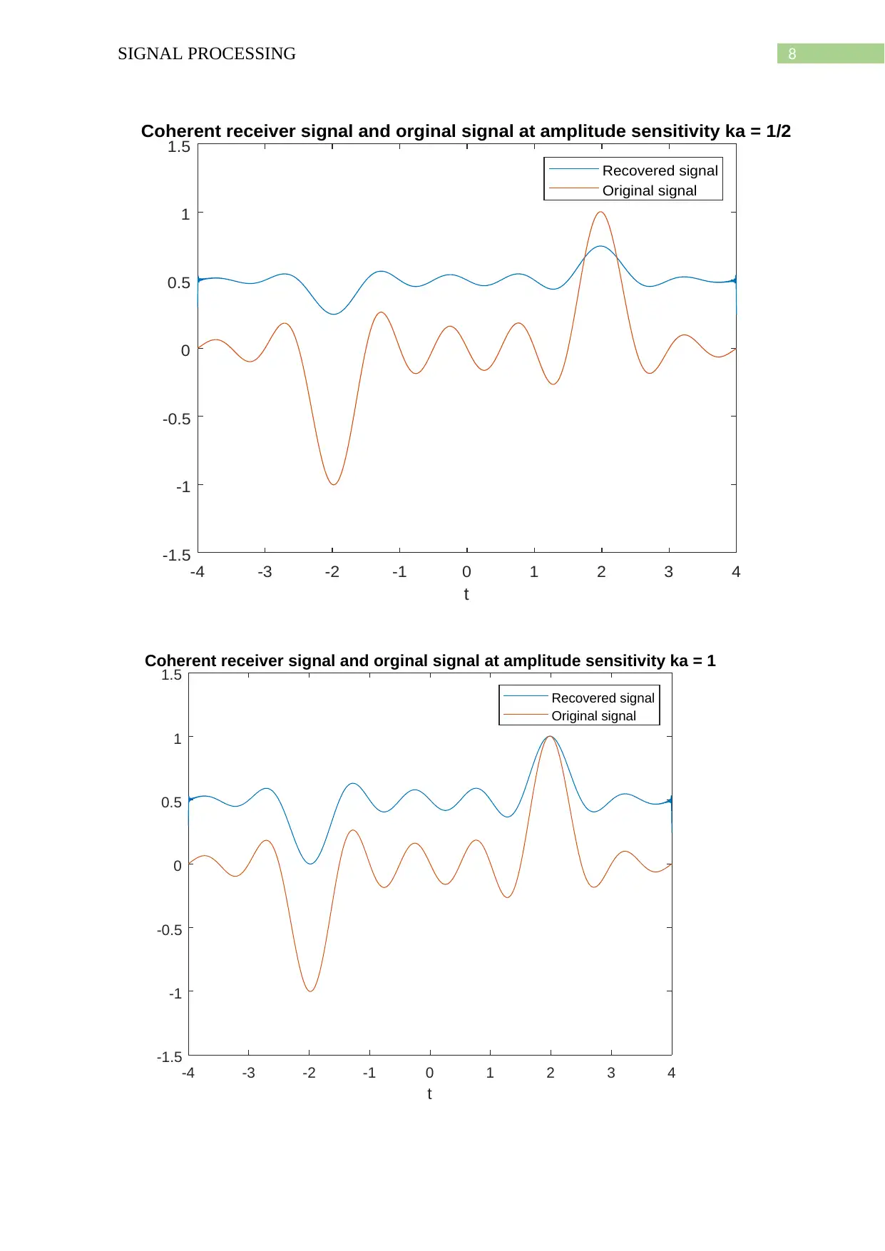
title('Coherent receiver signal and orginal signal at amplitude sensitivity ka = 1/2')
ka = 1;
s = (c.*(1+ka.*m)).*cos(2*pi*fc.*t);
[slp,tslp] = lowpass(s,t,fc);
figure(5)
plot(tslp,slp)
xlabel('t')
hold on
plot(t,m)
legend('Recovered signal','Original signal')
title('Coherent receiver signal and orginal signal at amplitude sensitivity ka = 1')
ka = 2;
s = (c.*(1+ka.*m)).*cos(2*pi*fc.*t);
[slp,tslp] = lowpass(s,t,fc);
figure(6)
hold on
plot(t,m)
legend('Recovered signal','Original signal')
title('Coherent receiver signal and orginal signal at amplitude sensitivity ka = 1/2')
ka = 1;
s = (c.*(1+ka.*m)).*cos(2*pi*fc.*t);
[slp,tslp] = lowpass(s,t,fc);
figure(5)
plot(tslp,slp)
xlabel('t')
hold on
plot(t,m)
legend('Recovered signal','Original signal')
title('Coherent receiver signal and orginal signal at amplitude sensitivity ka = 1')
ka = 2;
s = (c.*(1+ka.*m)).*cos(2*pi*fc.*t);
[slp,tslp] = lowpass(s,t,fc);
figure(6)
Paraphrase This Document
Need a fresh take? Get an instant paraphrase of this document with our AI Paraphraser
7SIGNAL PROCESSING
plot(tslp,slp)
xlabel('t')
hold on
plot(t,m)
legend('Recovered signal','Original signal')
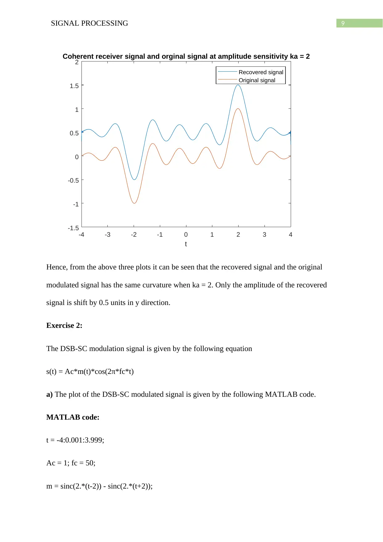
title('Coherent receiver signal and orginal signal at amplitude sensitivity ka = 2')
function [slp,tslp] = lowpass(s,ts,fcut)
B = fcut;
h = 2*B*sinc(2*B*ts);
N = length(ts);
Dty = ts(2)- ts(1);
tslp = ts;
slp = conv(h,s)*Dty;
slp = slp((N/2) + 1:(N/2) + N);
end
Plots:
8SIGNAL PROCESSING
-4 -3 -2 -1 0 1 2 3 4
t
-1.5
-1
-0.5
0
0.5
1
1.5
Coherent receiver signal and orginal signal at amplitude sensitivity ka = 1/2
Recovered signal
Original signal
-4 -3 -2 -1 0 1 2 3 4
t
-1.5
-1
-0.5
0
0.5
1
1.5
Coherent receiver signal and orginal signal at amplitude sensitivity ka = 1
Recovered signal
Original signal
-4 -3 -2 -1 0 1 2 3 4
t
-1.5
-1
-0.5
0
0.5
1
1.5
Coherent receiver signal and orginal signal at amplitude sensitivity ka = 1/2
Recovered signal
Original signal
-4 -3 -2 -1 0 1 2 3 4
t
-1.5
-1
-0.5
0
0.5
1
1.5
Coherent receiver signal and orginal signal at amplitude sensitivity ka = 1
Recovered signal
Original signal
9SIGNAL PROCESSING
-4 -3 -2 -1 0 1 2 3 4
t
-1.5
-1
-0.5
0
0.5
1
1.5
2
Coherent receiver signal and orginal signal at amplitude sensitivity ka = 2
Recovered signal
Original signal
Hence, from the above three plots it can be seen that the recovered signal and the original
modulated signal has the same curvature when ka = 2. Only the amplitude of the recovered
signal is shift by 0.5 units in y direction.
Exercise 2:
The DSB-SC modulation signal is given by the following equation
s(t) = Ac*m(t)*cos(2π*fc*t)
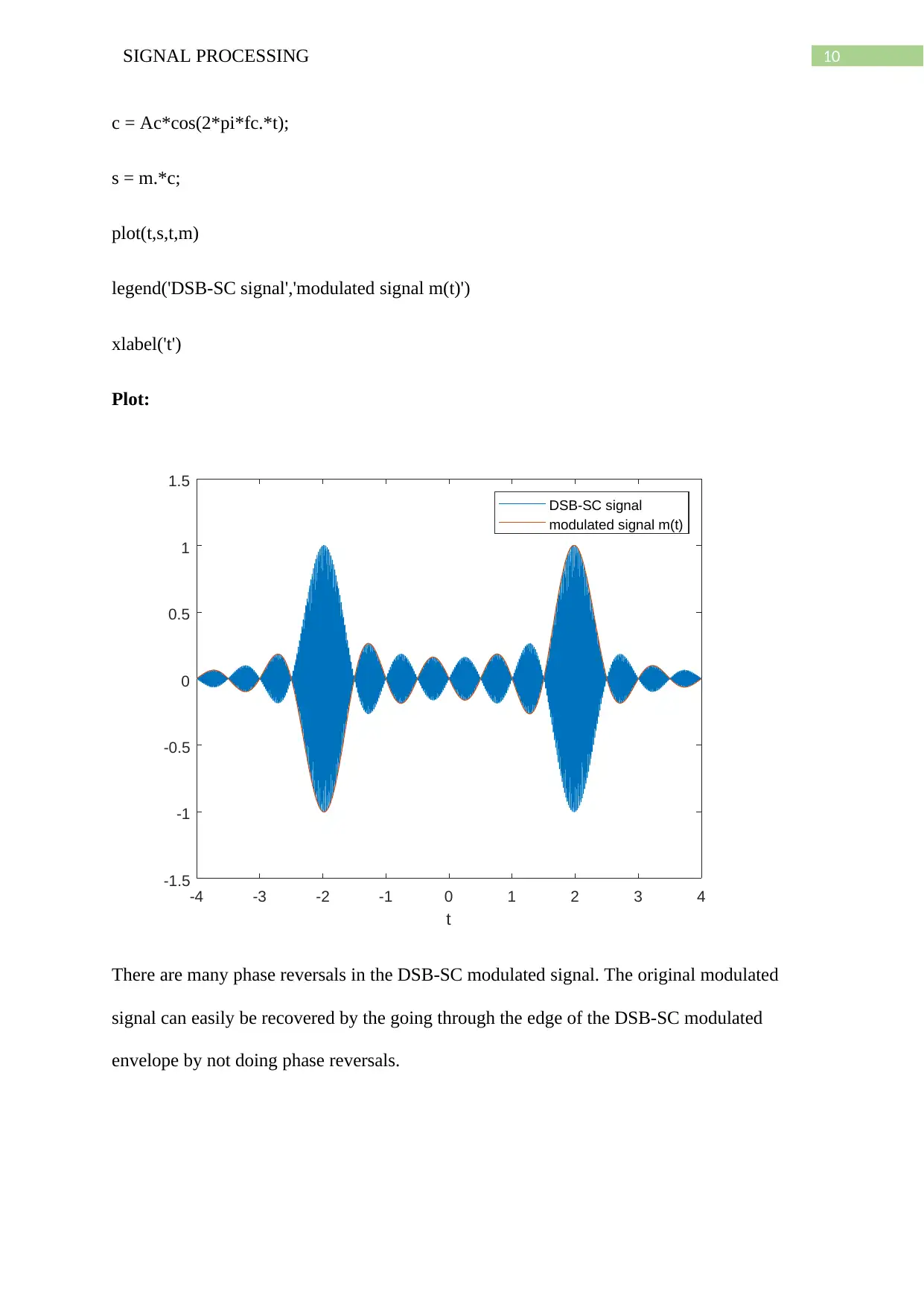
a) The plot of the DSB-SC modulated signal is given by the following MATLAB code.
MATLAB code:
t = -4:0.001:3.999;
Ac = 1; fc = 50;
m = sinc(2.*(t-2)) - sinc(2.*(t+2));
Secure Best Marks with AI Grader
Need help grading? Try our AI Grader for instant feedback on your assignments.
10SIGNAL PROCESSING
c = Ac*cos(2*pi*fc.*t);
s = m.*c;
plot(t,s,t,m)
legend('DSB-SC signal','modulated signal m(t)')
xlabel('t')
Plot:
-4 -3 -2 -1 0 1 2 3 4
t
-1.5
-1
-0.5
0
0.5
1
1.5
DSB-SC signal
modulated signal m(t)
There are many phase reversals in the DSB-SC modulated signal. The original modulated
signal can easily be recovered by the going through the edge of the DSB-SC modulated
envelope by not doing phase reversals.
11SIGNAL PROCESSING
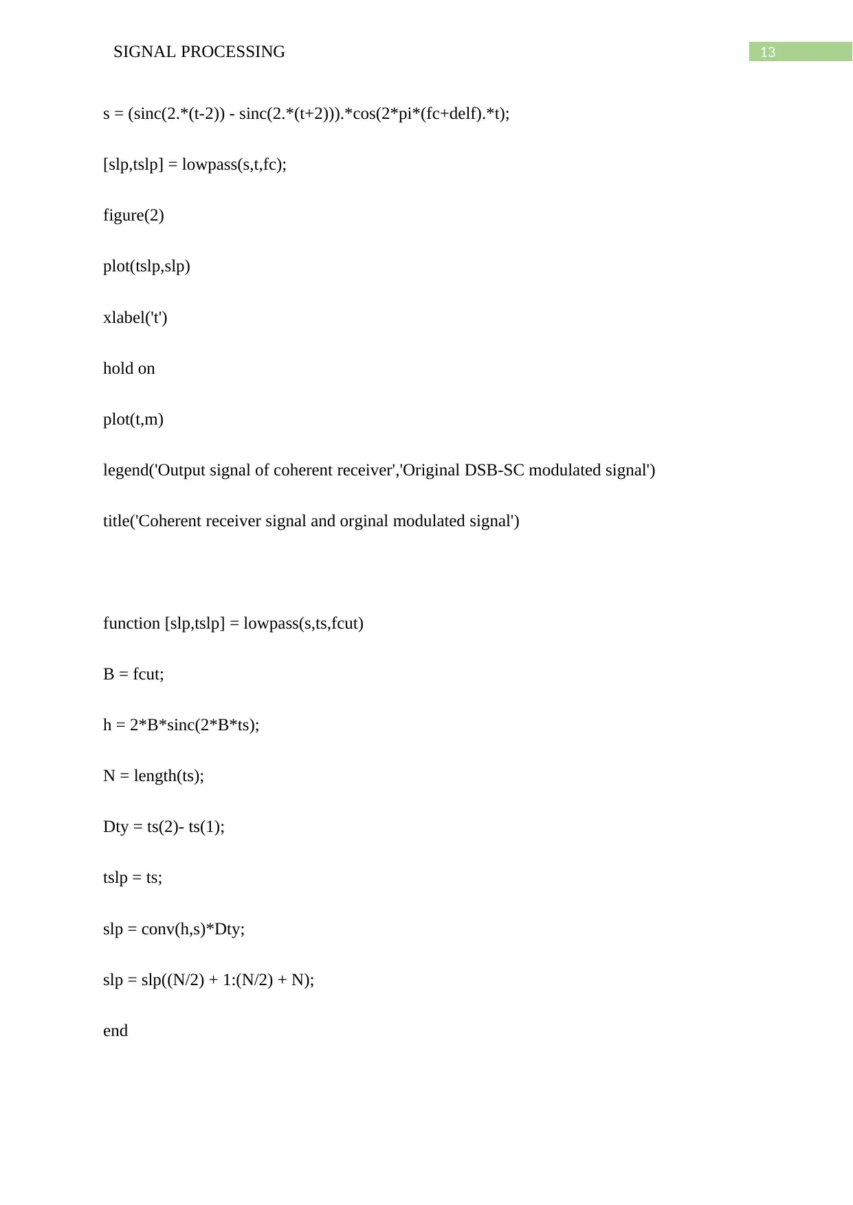
b) Now, the output of the coherent receiver where the DSB-SC modulated signal is
multiplied by a carrier wave of 50 Hz and then passed through a low pass filter of cut-off
frequency of 50 Hz is obtained by the following MATLAB code as given below.
MATLAB code:
t = -4:0.001:3.999;
s = (m.*c).*cos(2*pi*(fc).*t);
[slp,tslp] = lowpass(s,t,fc);
figure(2)
plot(tslp,slp)
xlabel('t')
hold on
plot(t,m)
legend('Output signal of coherent receiver','Original DSB-SC modulated signal')
title('Coherent receiver signal and orginal modulated signal')
function [slp,tslp] = lowpass(s,ts,fcut)
B = fcut;
h = 2*B*sinc(2*B*ts);
N = length(ts);
Dty = ts(2)- ts(1);
tslp = ts;
12SIGNAL PROCESSING
slp = conv(h,s)*Dty;
slp = slp((N/2) + 1:(N/2) + N);
end
Plot:
-4 -3 -2 -1 0 1 2 3 4
t
-1.5
-1
-0.5
0
0.5
1
1.5 Coherent receiver signal and orginal modulated signal
Output signal of coherent receiver
Original DSB-SC modulated signal
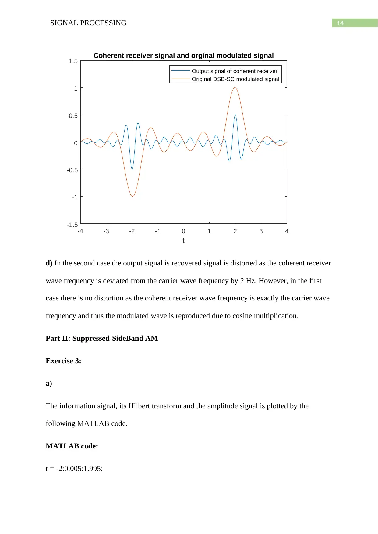
c) Now, the DSB-SC signal is multiplied by carrier wave of cos (2*π(fc + ∇f)t)
Where, ∇f = 2 Hz.
MATLAB code:
t = -4:0.001:3.999;
delf = 2;
Paraphrase This Document
Need a fresh take? Get an instant paraphrase of this document with our AI Paraphraser
13SIGNAL PROCESSING
s = (sinc(2.*(t-2)) - sinc(2.*(t+2))).*cos(2*pi*(fc+delf).*t);
[slp,tslp] = lowpass(s,t,fc);
figure(2)
plot(tslp,slp)
xlabel('t')
hold on
plot(t,m)
legend('Output signal of coherent receiver','Original DSB-SC modulated signal')
title('Coherent receiver signal and orginal modulated signal')
function [slp,tslp] = lowpass(s,ts,fcut)
B = fcut;
h = 2*B*sinc(2*B*ts);
N = length(ts);
Dty = ts(2)- ts(1);
tslp = ts;
slp = conv(h,s)*Dty;
slp = slp((N/2) + 1:(N/2) + N);
end
14SIGNAL PROCESSING
-4 -3 -2 -1 0 1 2 3 4
t
-1.5
-1
-0.5
0
0.5
1
1.5 Coherent receiver signal and orginal modulated signal
Output signal of coherent receiver
Original DSB-SC modulated signal
d) In the second case the output signal is recovered signal is distorted as the coherent receiver
wave frequency is deviated from the carrier wave frequency by 2 Hz. However, in the first
case there is no distortion as the coherent receiver wave frequency is exactly the carrier wave
frequency and thus the modulated wave is reproduced due to cosine multiplication.
Part II: Suppressed-SideBand AM
Exercise 3:
a)
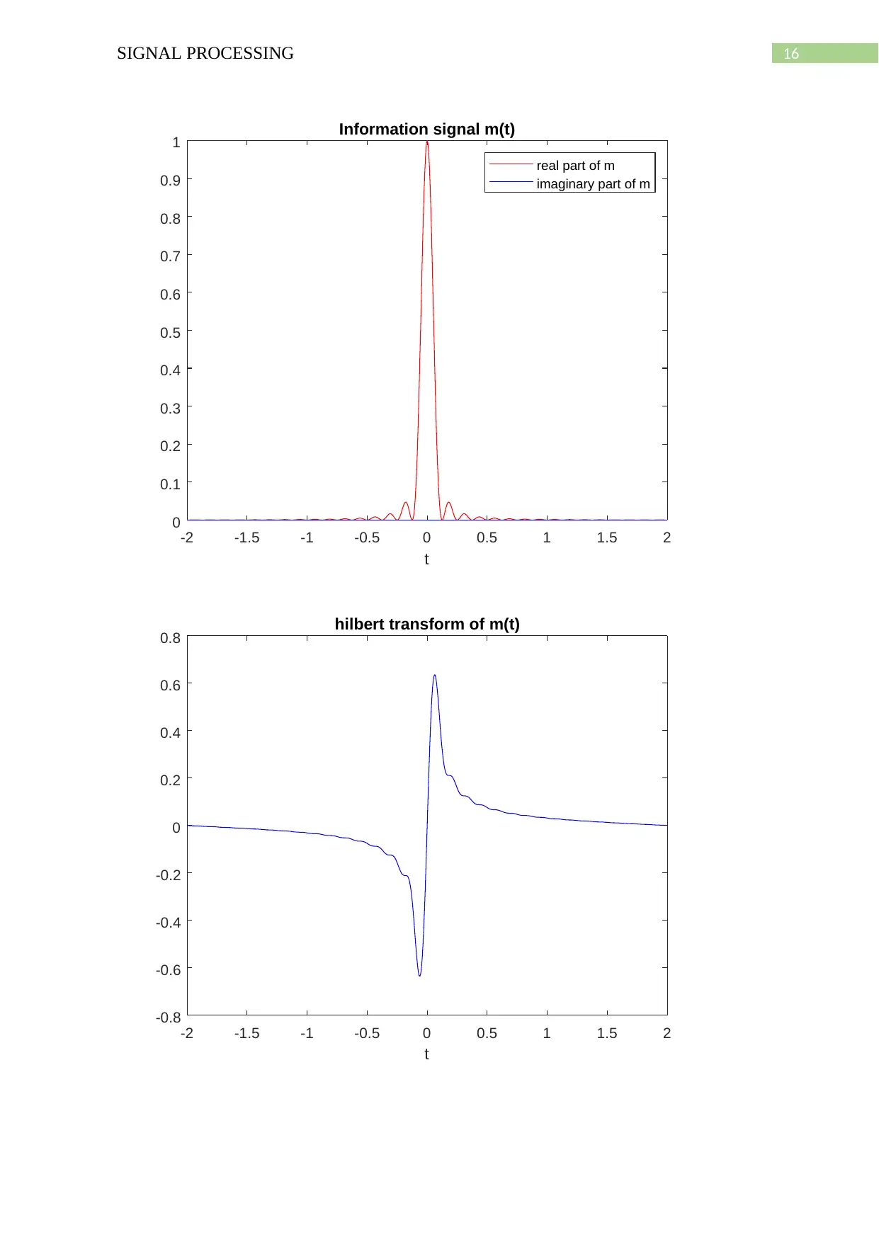
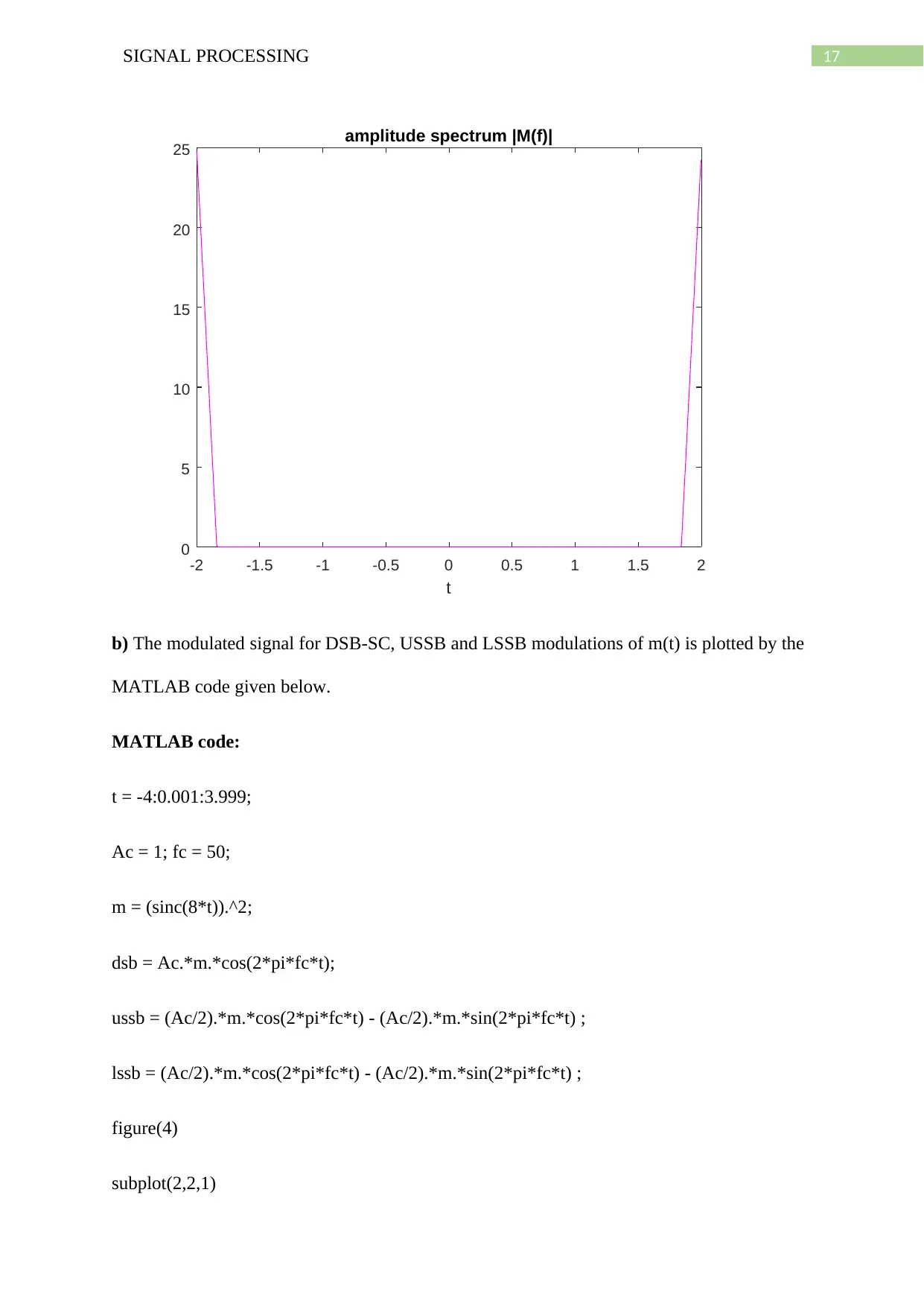
The information signal, its Hilbert transform and the amplitude signal is plotted by the
following MATLAB code.
MATLAB code:
t = -2:0.005:1.995;
15SIGNAL PROCESSING
Ac = 1; fc = 50;
m = (sinc(8*t)).^2;
mhat = imag(hilbert(m));
mamp = abs(fft(m));
figure(1)
plot(t,real(m),'r-',t,imag(m),'b-')
xlabel('t')
legend('real part of m','imaginary part of m')
title('Information signal m(t)')
figure(2)
plot(t,mhat,'b-')
xlabel('t')
title('hilbert transform of m(t)')
figure(3)
plot(t,mamp,'m-')
xlabel('t')
title('amplitude spectrum |M(f)|')
Plot:
Secure Best Marks with AI Grader
Need help grading? Try our AI Grader for instant feedback on your assignments.
16SIGNAL PROCESSING
-2 -1.5 -1 -0.5 0 0.5 1 1.5 2
t
0
0.1
0.2
0.3
0.4
0.5
0.6
0.7
0.8
0.9
1 Information signal m(t)
real part of m
imaginary part of m
-2 -1.5 -1 -0.5 0 0.5 1 1.5 2
t
-0.8
-0.6
-0.4
-0.2
0
0.2
0.4
0.6
0.8 hilbert transform of m(t)
-2 -1.5 -1 -0.5 0 0.5 1 1.5 2
t
0
0.1
0.2
0.3
0.4
0.5
0.6
0.7
0.8
0.9
1 Information signal m(t)
real part of m
imaginary part of m
-2 -1.5 -1 -0.5 0 0.5 1 1.5 2
t
-0.8
-0.6
-0.4
-0.2
0
0.2
0.4
0.6
0.8 hilbert transform of m(t)
17SIGNAL PROCESSING
-2 -1.5 -1 -0.5 0 0.5 1 1.5 2
t
0
5
10
15
20
25 amplitude spectrum |M(f)|
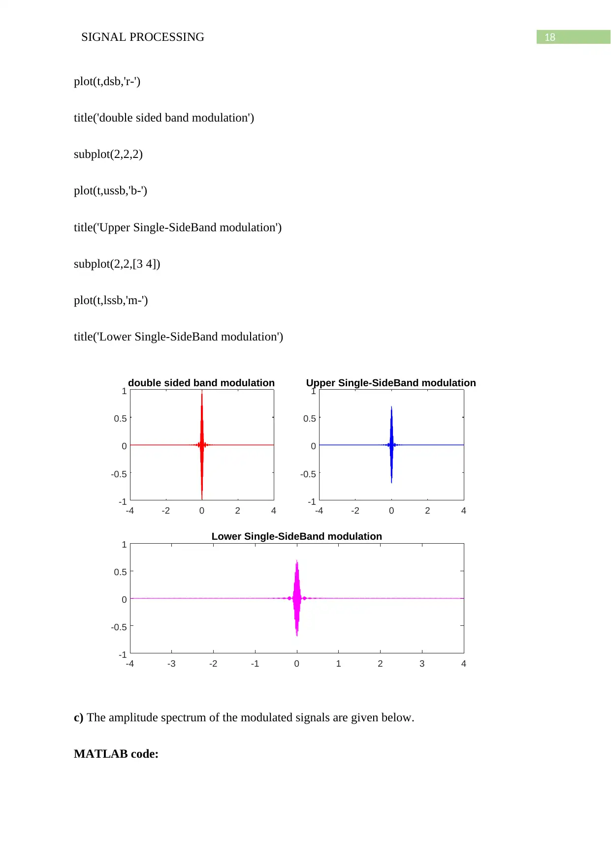
b) The modulated signal for DSB-SC, USSB and LSSB modulations of m(t) is plotted by the
MATLAB code given below.
MATLAB code:
t = -4:0.001:3.999;
Ac = 1; fc = 50;
m = (sinc(8*t)).^2;
dsb = Ac.*m.*cos(2*pi*fc*t);
ussb = (Ac/2).*m.*cos(2*pi*fc*t) - (Ac/2).*m.*sin(2*pi*fc*t) ;
lssb = (Ac/2).*m.*cos(2*pi*fc*t) - (Ac/2).*m.*sin(2*pi*fc*t) ;
figure(4)
subplot(2,2,1)
18SIGNAL PROCESSING
plot(t,dsb,'r-')
title('double sided band modulation')
subplot(2,2,2)
plot(t,ussb,'b-')
title('Upper Single-SideBand modulation')
subplot(2,2,[3 4])
plot(t,lssb,'m-')
title('Lower Single-SideBand modulation')
-4 -2 0 2 4
-1
-0.5
0
0.5
1 double sided band modulation
-4 -2 0 2 4
-1
-0.5
0
0.5
1
Upper Single-SideBand modulation
-4 -3 -2 -1 0 1 2 3 4
-1
-0.5
0
0.5
1 Lower Single-SideBand modulation
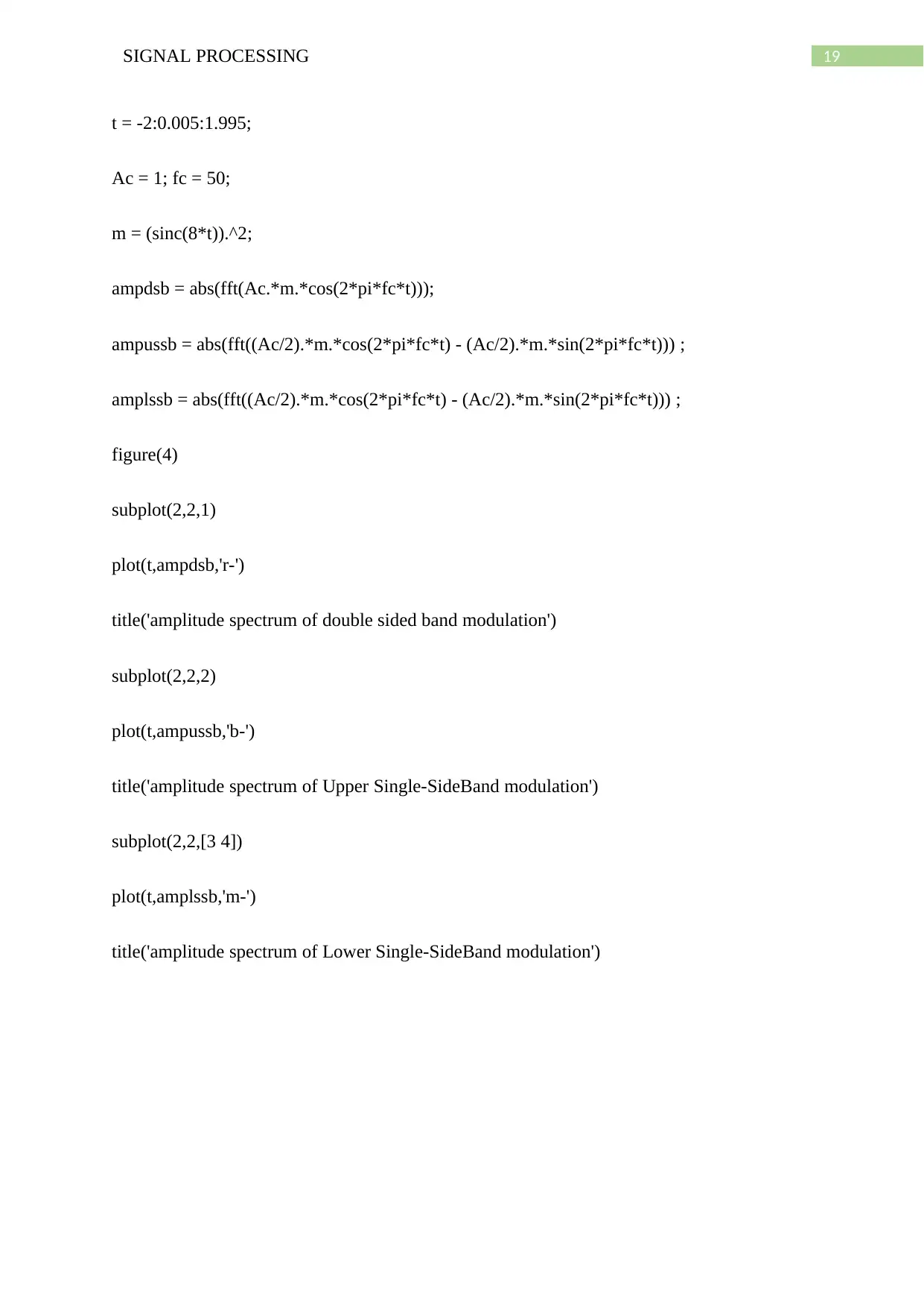
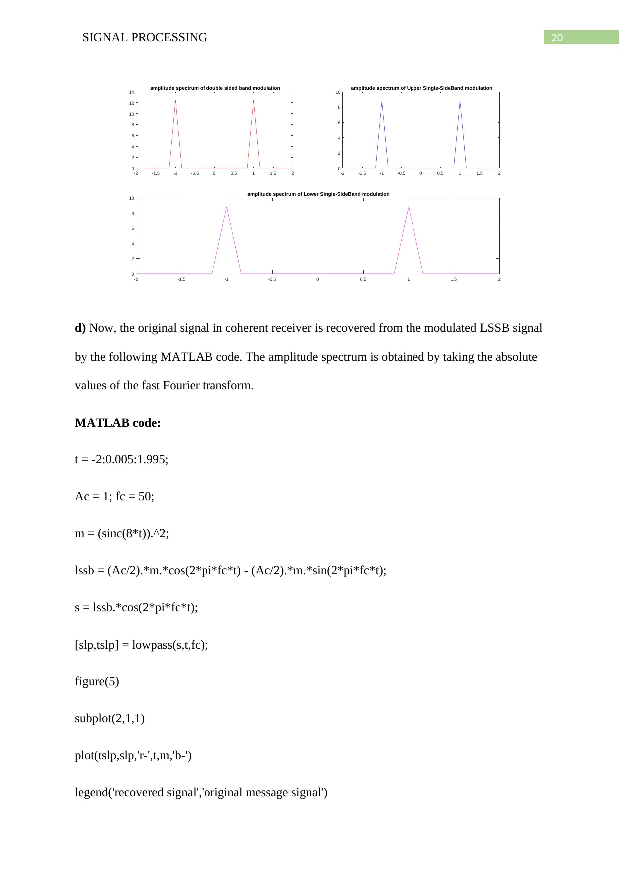
c) The amplitude spectrum of the modulated signals are given below.
MATLAB code:
Paraphrase This Document
Need a fresh take? Get an instant paraphrase of this document with our AI Paraphraser
19SIGNAL PROCESSING
t = -2:0.005:1.995;
Ac = 1; fc = 50;
m = (sinc(8*t)).^2;
ampdsb = abs(fft(Ac.*m.*cos(2*pi*fc*t)));
ampussb = abs(fft((Ac/2).*m.*cos(2*pi*fc*t) - (Ac/2).*m.*sin(2*pi*fc*t))) ;
amplssb = abs(fft((Ac/2).*m.*cos(2*pi*fc*t) - (Ac/2).*m.*sin(2*pi*fc*t))) ;
figure(4)
subplot(2,2,1)
plot(t,ampdsb,'r-')
title('amplitude spectrum of double sided band modulation')
subplot(2,2,2)
plot(t,ampussb,'b-')
title('amplitude spectrum of Upper Single-SideBand modulation')
subplot(2,2,[3 4])
plot(t,amplssb,'m-')
title('amplitude spectrum of Lower Single-SideBand modulation')
20SIGNAL PROCESSING
-2 -1.5 -1 -0.5 0 0.5 1 1.5 2
0
2
4
6
8
10
12
14 amplitude spectrum of double sided band modulation
-2 -1.5 -1 -0.5 0 0.5 1 1.5 2
0
2
4
6
8
10 amplitude spectrum of Upper Single-SideBand modulation
-2 -1.5 -1 -0.5 0 0.5 1 1.5 2
0
2
4
6
8
10 amplitude spectrum of Lower Single-SideBand modulation
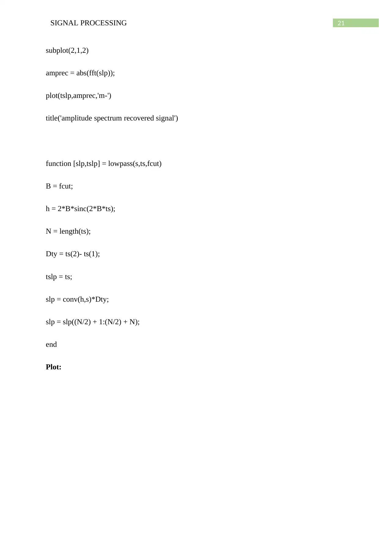
d) Now, the original signal in coherent receiver is recovered from the modulated LSSB signal
by the following MATLAB code. The amplitude spectrum is obtained by taking the absolute
values of the fast Fourier transform.
MATLAB code:
t = -2:0.005:1.995;
Ac = 1; fc = 50;
m = (sinc(8*t)).^2;
lssb = (Ac/2).*m.*cos(2*pi*fc*t) - (Ac/2).*m.*sin(2*pi*fc*t);
s = lssb.*cos(2*pi*fc*t);
[slp,tslp] = lowpass(s,t,fc);
figure(5)
subplot(2,1,1)
plot(tslp,slp,'r-',t,m,'b-')
legend('recovered signal','original message signal')
-2 -1.5 -1 -0.5 0 0.5 1 1.5 2
0
2
4
6
8
10
12
14 amplitude spectrum of double sided band modulation
-2 -1.5 -1 -0.5 0 0.5 1 1.5 2
0
2
4
6
8
10 amplitude spectrum of Upper Single-SideBand modulation
-2 -1.5 -1 -0.5 0 0.5 1 1.5 2
0
2
4
6
8
10 amplitude spectrum of Lower Single-SideBand modulation
d) Now, the original signal in coherent receiver is recovered from the modulated LSSB signal
by the following MATLAB code. The amplitude spectrum is obtained by taking the absolute
values of the fast Fourier transform.
MATLAB code:
t = -2:0.005:1.995;
Ac = 1; fc = 50;
m = (sinc(8*t)).^2;
lssb = (Ac/2).*m.*cos(2*pi*fc*t) - (Ac/2).*m.*sin(2*pi*fc*t);
s = lssb.*cos(2*pi*fc*t);
[slp,tslp] = lowpass(s,t,fc);
figure(5)
subplot(2,1,1)
plot(tslp,slp,'r-',t,m,'b-')
legend('recovered signal','original message signal')
21SIGNAL PROCESSING
subplot(2,1,2)
amprec = abs(fft(slp));
plot(tslp,amprec,'m-')
title('amplitude spectrum recovered signal')
function [slp,tslp] = lowpass(s,ts,fcut)
B = fcut;
h = 2*B*sinc(2*B*ts);
N = length(ts);
Dty = ts(2)- ts(1);
tslp = ts;
slp = conv(h,s)*Dty;
slp = slp((N/2) + 1:(N/2) + N);
end
Plot:
subplot(2,1,2)
amprec = abs(fft(slp));
plot(tslp,amprec,'m-')
title('amplitude spectrum recovered signal')
function [slp,tslp] = lowpass(s,ts,fcut)
B = fcut;
h = 2*B*sinc(2*B*ts);
N = length(ts);
Dty = ts(2)- ts(1);
tslp = ts;
slp = conv(h,s)*Dty;
slp = slp((N/2) + 1:(N/2) + N);
end
Plot:
Secure Best Marks with AI Grader
Need help grading? Try our AI Grader for instant feedback on your assignments.
22SIGNAL PROCESSING
-2 -1.5 -1 -0.5 0 0.5 1 1.5 2
0
0.5
1
recovered signal
original message signal
-2 -1.5 -1 -0.5 0 0.5 1 1.5 2
0
2
4
6
amplitude spectrum recovered signal
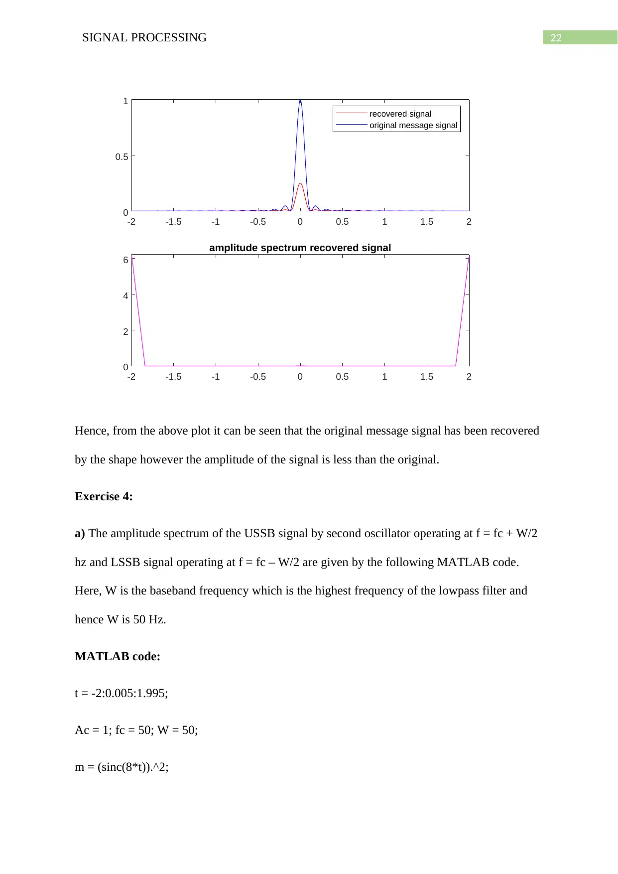
Hence, from the above plot it can be seen that the original message signal has been recovered
by the shape however the amplitude of the signal is less than the original.
Exercise 4:
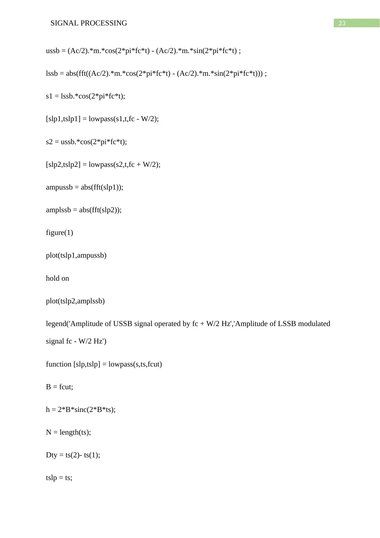
a) The amplitude spectrum of the USSB signal by second oscillator operating at f = fc + W/2
hz and LSSB signal operating at f = fc – W/2 are given by the following MATLAB code.
Here, W is the baseband frequency which is the highest frequency of the lowpass filter and
hence W is 50 Hz.
MATLAB code:
t = -2:0.005:1.995;
Ac = 1; fc = 50; W = 50;
m = (sinc(8*t)).^2;
-2 -1.5 -1 -0.5 0 0.5 1 1.5 2
0
0.5
1
recovered signal
original message signal
-2 -1.5 -1 -0.5 0 0.5 1 1.5 2
0
2
4
6
amplitude spectrum recovered signal
Hence, from the above plot it can be seen that the original message signal has been recovered
by the shape however the amplitude of the signal is less than the original.
Exercise 4:
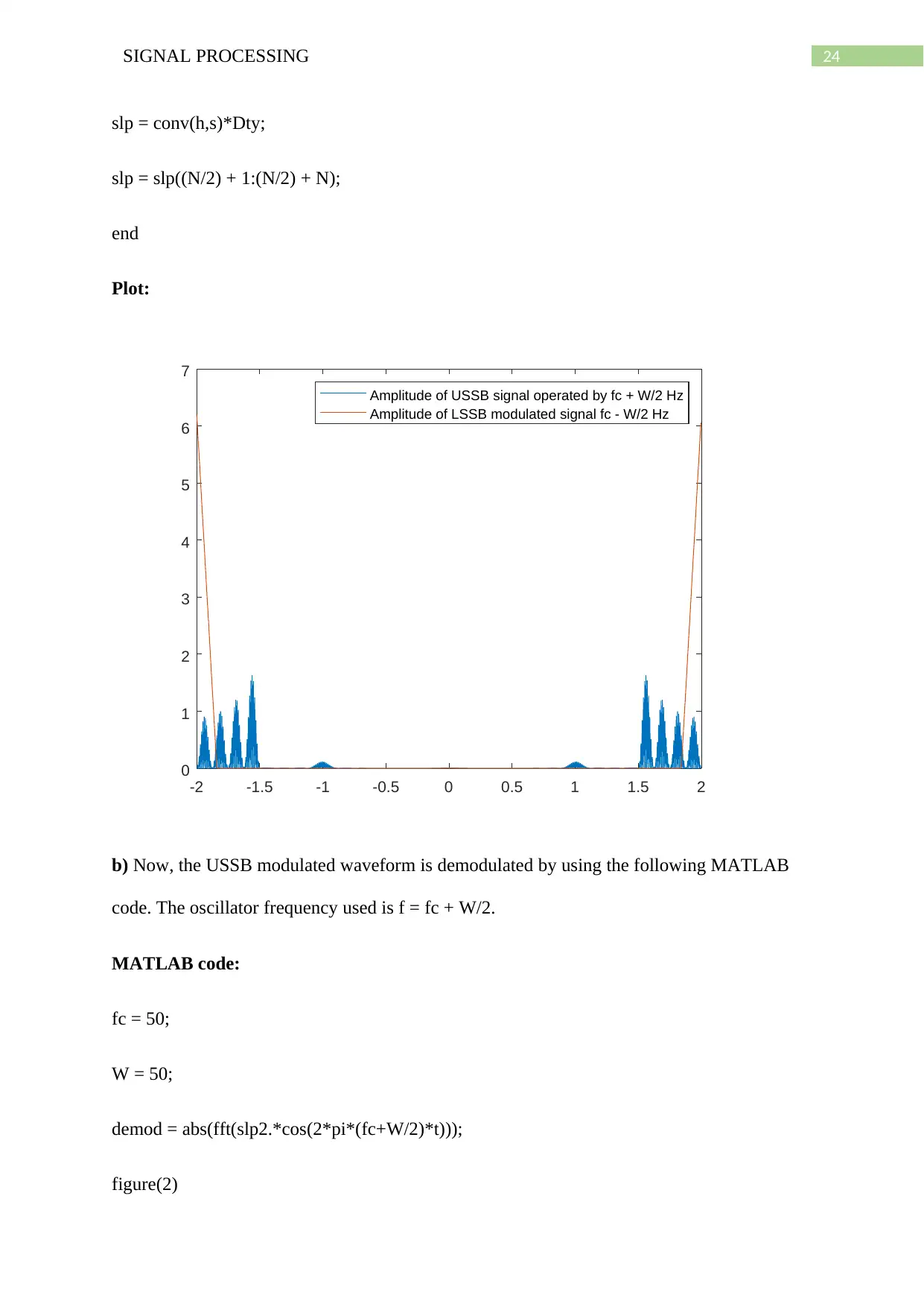
a) The amplitude spectrum of the USSB signal by second oscillator operating at f = fc + W/2
hz and LSSB signal operating at f = fc – W/2 are given by the following MATLAB code.
Here, W is the baseband frequency which is the highest frequency of the lowpass filter and
hence W is 50 Hz.
MATLAB code:
t = -2:0.005:1.995;
Ac = 1; fc = 50; W = 50;
m = (sinc(8*t)).^2;
23SIGNAL PROCESSING
ussb = (Ac/2).*m.*cos(2*pi*fc*t) - (Ac/2).*m.*sin(2*pi*fc*t) ;
lssb = abs(fft((Ac/2).*m.*cos(2*pi*fc*t) - (Ac/2).*m.*sin(2*pi*fc*t))) ;
s1 = lssb.*cos(2*pi*fc*t);
[slp1,tslp1] = lowpass(s1,t,fc - W/2);
s2 = ussb.*cos(2*pi*fc*t);
[slp2,tslp2] = lowpass(s2,t,fc + W/2);
ampussb = abs(fft(slp1));
amplssb = abs(fft(slp2));
figure(1)
plot(tslp1,ampussb)
hold on
plot(tslp2,amplssb)
legend('Amplitude of USSB signal operated by fc + W/2 Hz','Amplitude of LSSB modulated
signal fc - W/2 Hz')
function [slp,tslp] = lowpass(s,ts,fcut)
B = fcut;
h = 2*B*sinc(2*B*ts);
N = length(ts);
Dty = ts(2)- ts(1);
tslp = ts;
24SIGNAL PROCESSING
slp = conv(h,s)*Dty;
slp = slp((N/2) + 1:(N/2) + N);
end
Plot:
-2 -1.5 -1 -0.5 0 0.5 1 1.5 2
0
1
2
3
4
5
6
7
Amplitude of USSB signal operated by fc + W/2 Hz
Amplitude of LSSB modulated signal fc - W/2 Hz
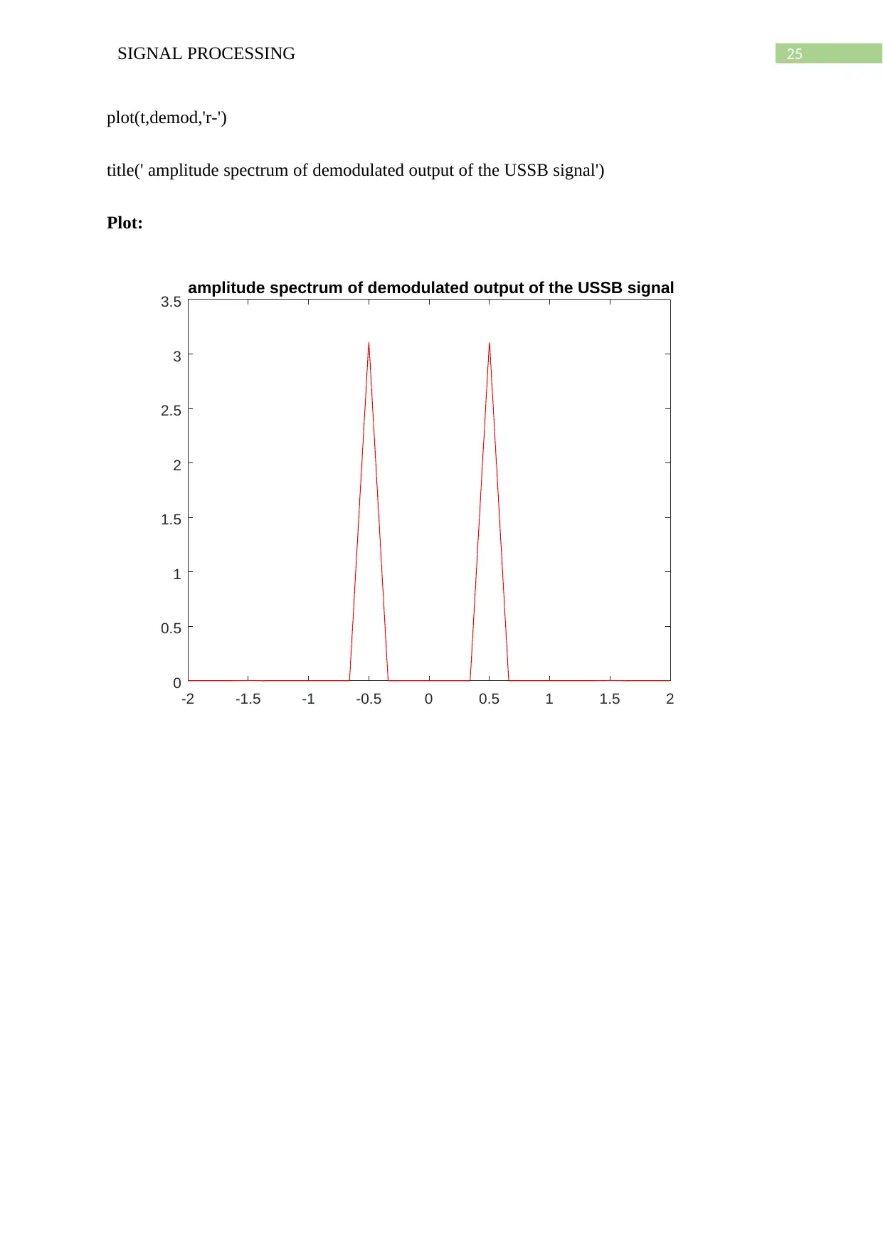
b) Now, the USSB modulated waveform is demodulated by using the following MATLAB
code. The oscillator frequency used is f = fc + W/2.
MATLAB code:
fc = 50;
W = 50;
demod = abs(fft(slp2.*cos(2*pi*(fc+W/2)*t)));
figure(2)
Paraphrase This Document
Need a fresh take? Get an instant paraphrase of this document with our AI Paraphraser
25SIGNAL PROCESSING
plot(t,demod,'r-')
title(' amplitude spectrum of demodulated output of the USSB signal')
Plot:
-2 -1.5 -1 -0.5 0 0.5 1 1.5 2
0
0.5
1
1.5
2
2.5
3
3.5 amplitude spectrum of demodulated output of the USSB signal
plot(t,demod,'r-')
title(' amplitude spectrum of demodulated output of the USSB signal')
Plot:
-2 -1.5 -1 -0.5 0 0.5 1 1.5 2
0
0.5
1
1.5
2
2.5
3
3.5 amplitude spectrum of demodulated output of the USSB signal
1 out of 26
Related Documents
Your All-in-One AI-Powered Toolkit for Academic Success.
+13062052269
info@desklib.com
Available 24*7 on WhatsApp / Email
![[object Object]](/_next/static/media/star-bottom.7253800d.svg)
Unlock your academic potential
© 2024 | Zucol Services PVT LTD | All rights reserved.


