Signal Processing Methodology for Sine/Cosine Sensors Analysis
VerifiedAdded on 2023/04/25
|7
|1521
|199
Homework Assignment
AI Summary
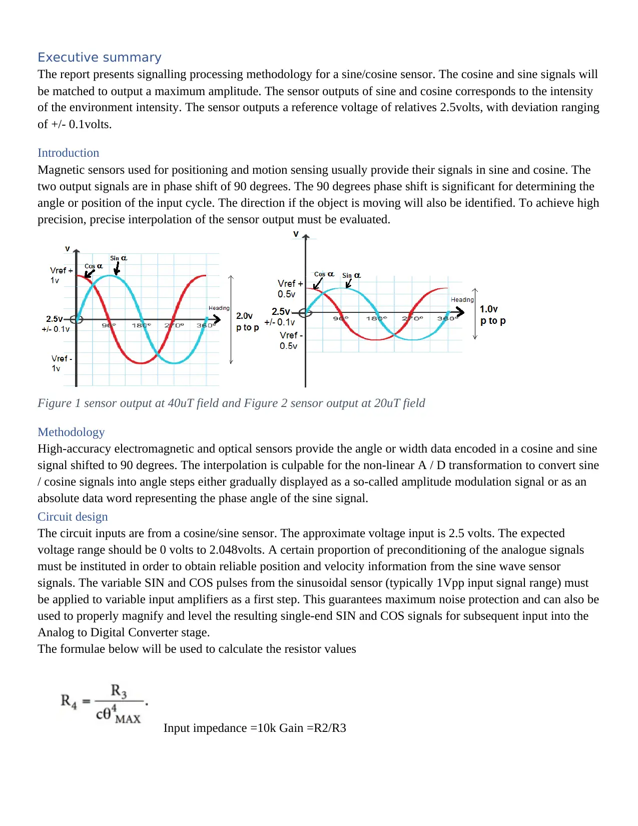
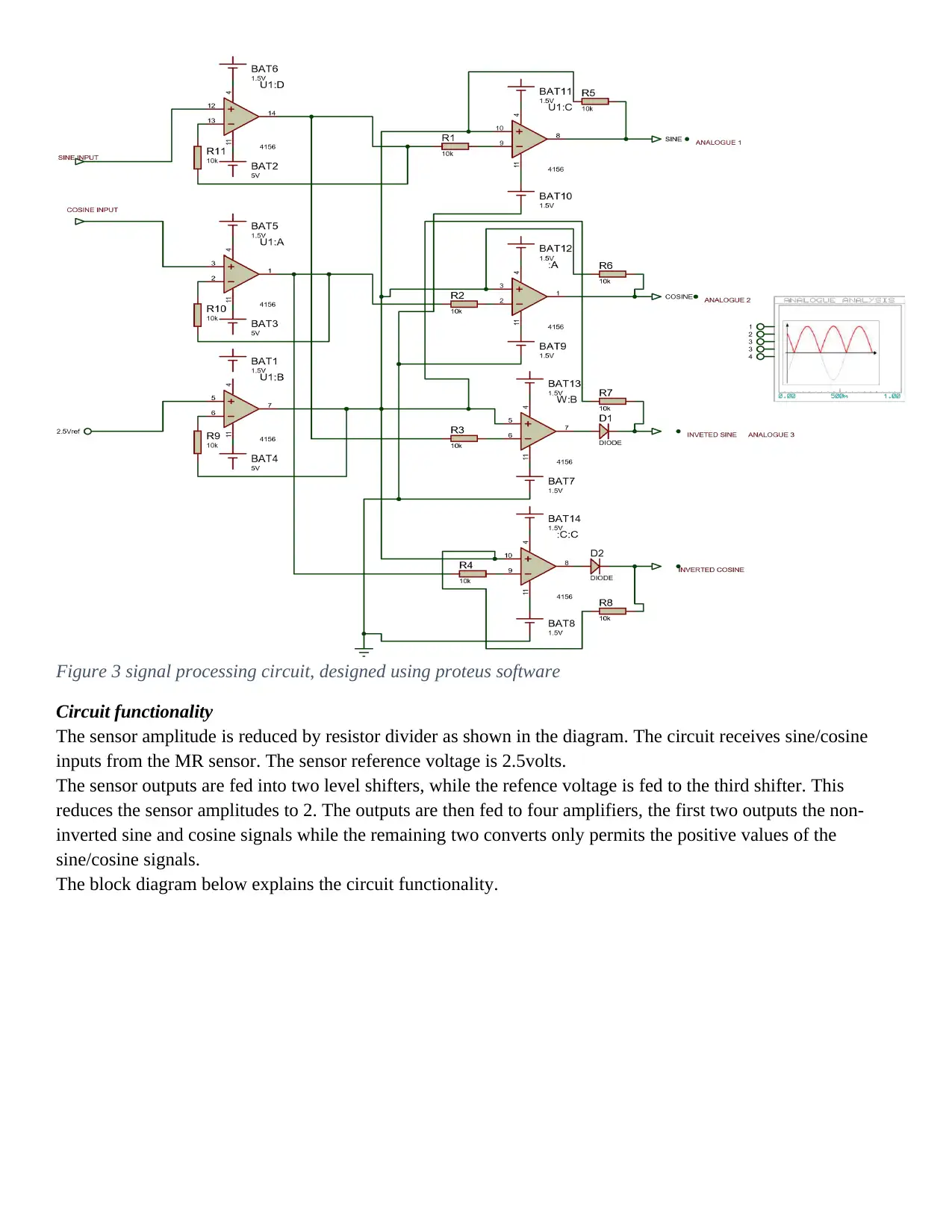
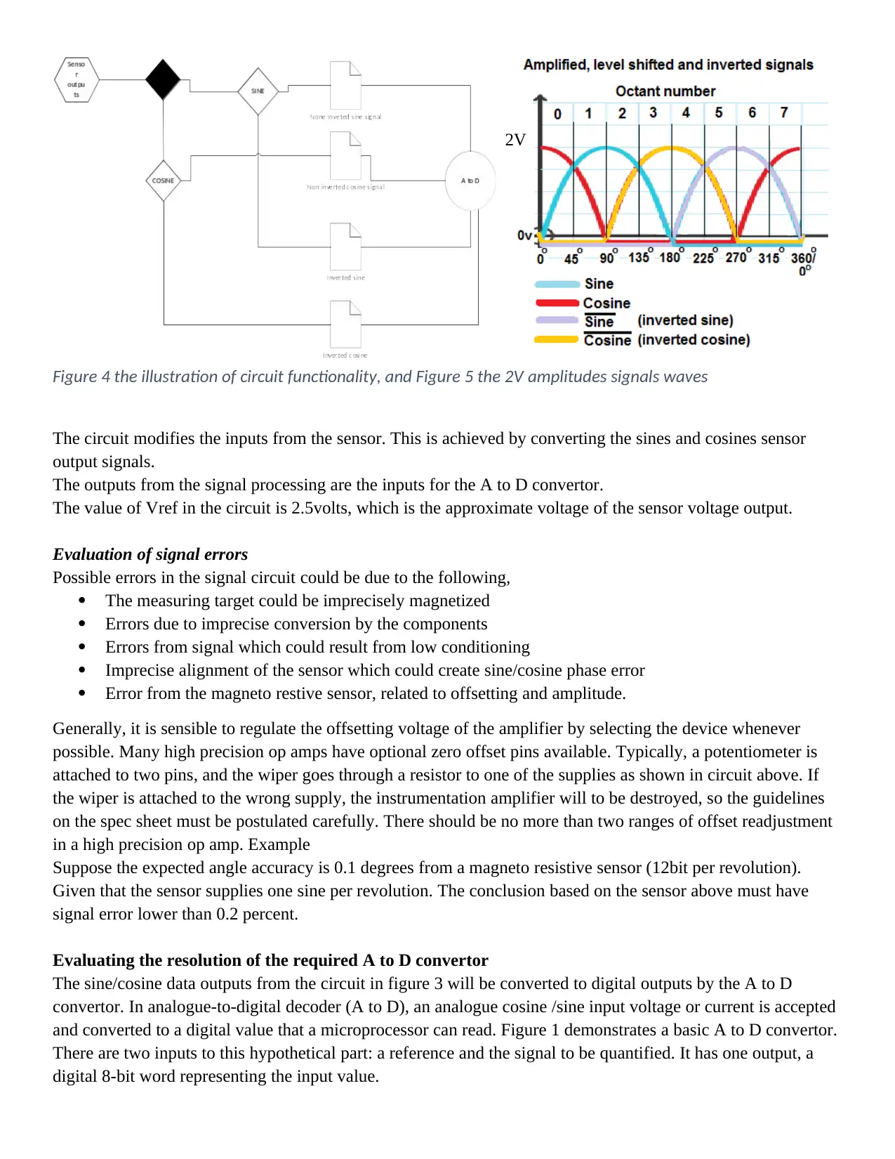
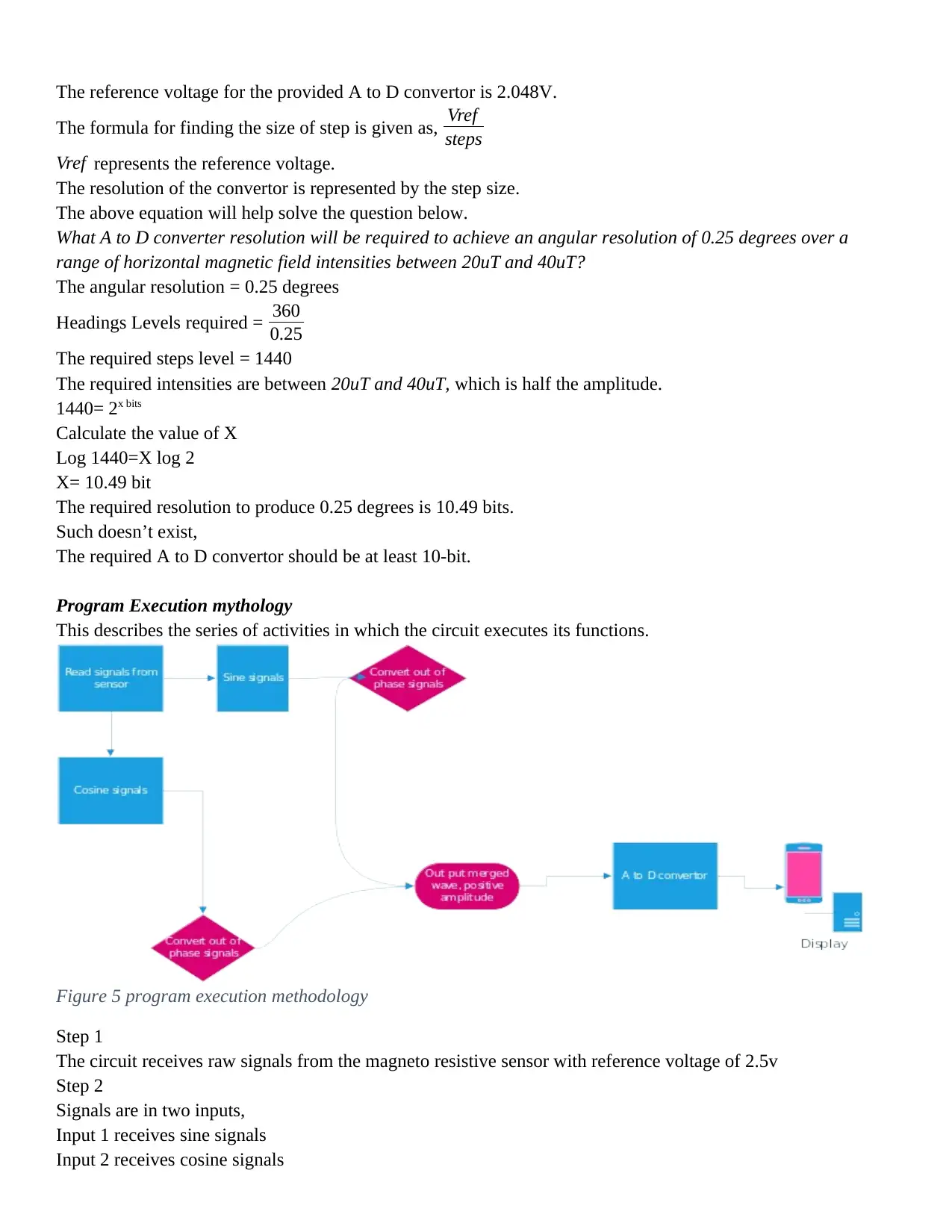
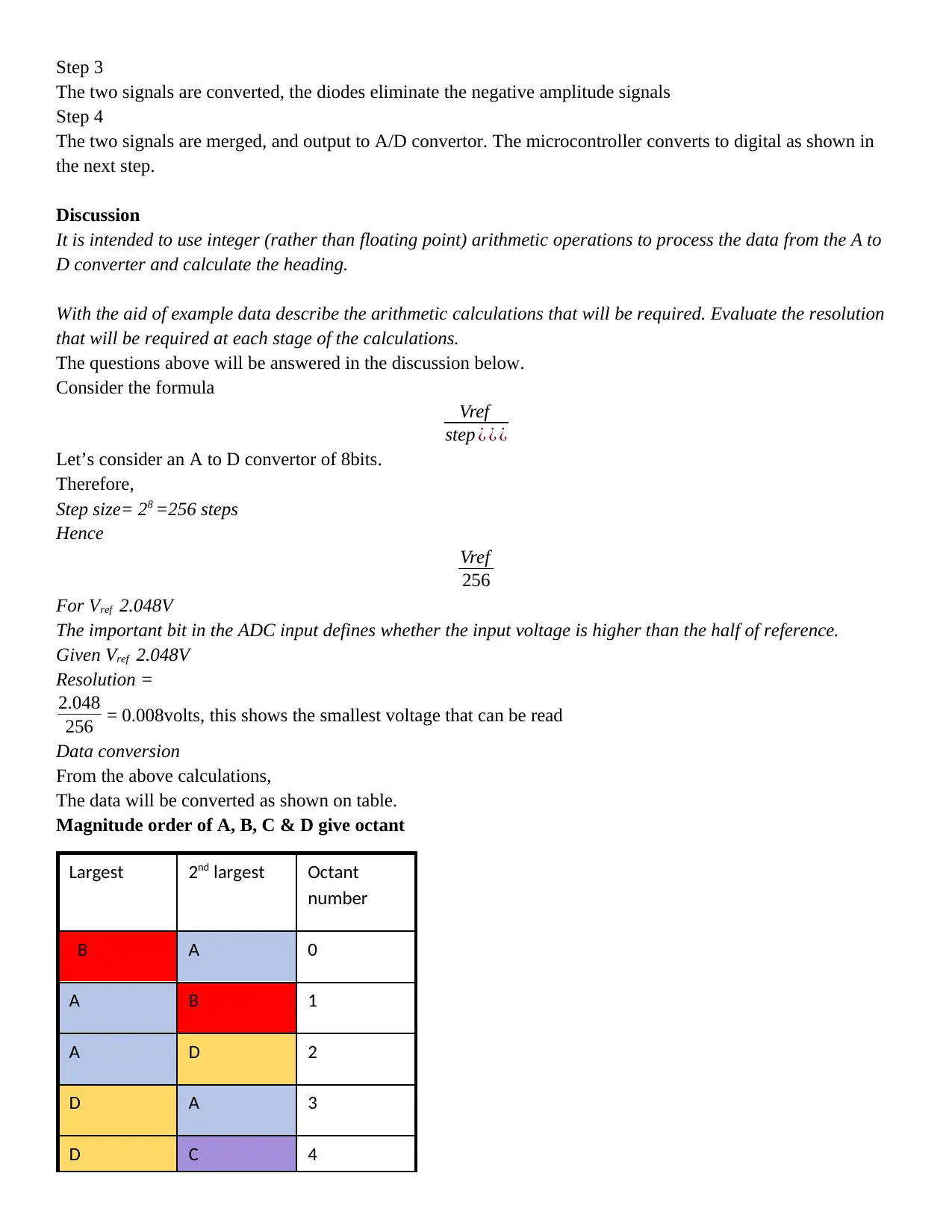
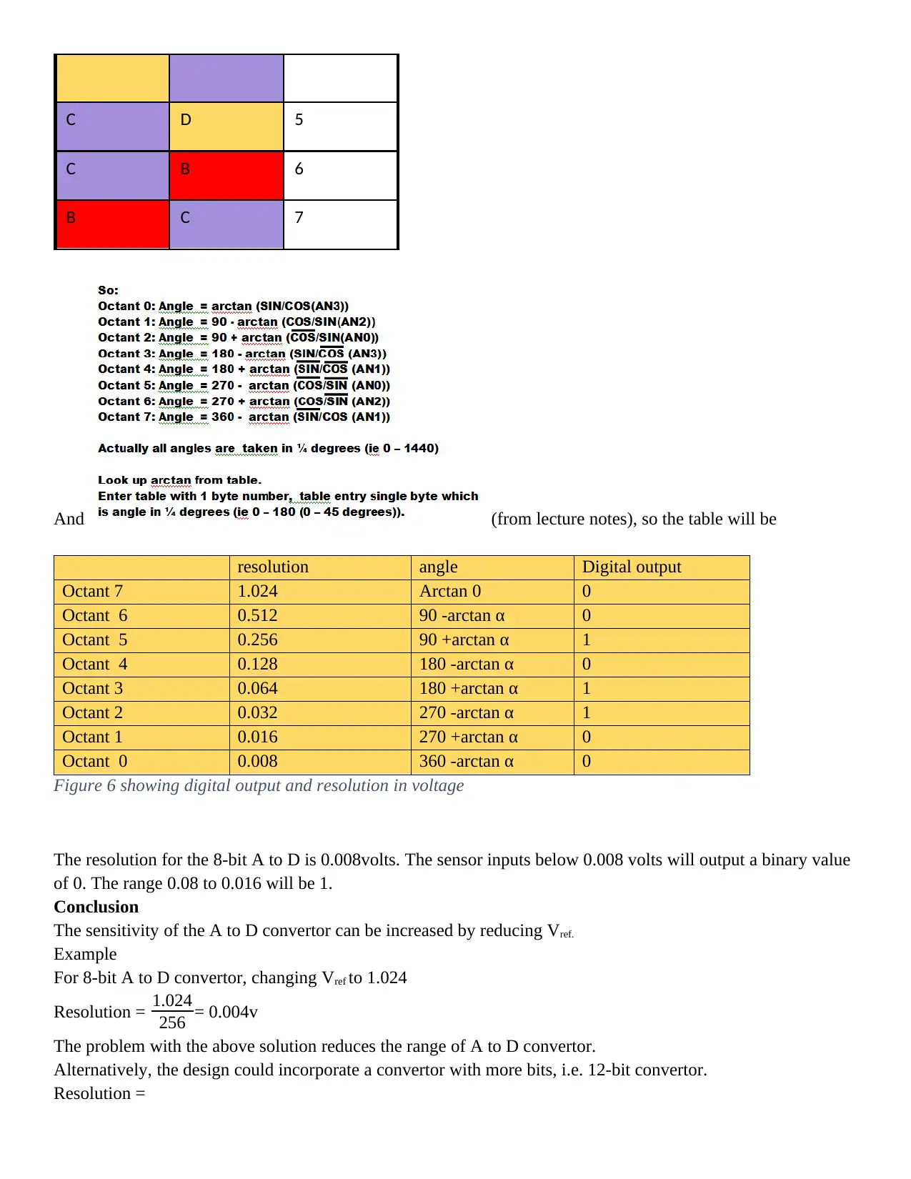
This report presents a detailed analysis of signal processing methodologies for a sine/cosine sensor, focusing on the conversion of sine and cosine signals to determine environmental intensity. It covers circuit design using Proteus software, including amplifier configurations and level shifters to process sensor outputs. The report then evaluates potential signal errors, such as those arising from sensor misalignment or component inaccuracies. Furthermore, it explores the resolution requirements for an A/D converter to achieve specific angular resolutions, calculating the necessary bit depth for accurate digital conversion. The methodology is explained through a program execution, and the report concludes with a discussion on integer arithmetic for data processing and resolution requirements at each stage of the calculations. Finally, the report provides an example of data conversion and the impact of Vref on the A/D converter sensitivity.

1 out of 7


Your All-in-One AI-Powered Toolkit for Academic Success.
+13062052269
info@desklib.com
Available 24*7 on WhatsApp / Email
![[object Object]](/_next/static/media/star-bottom.7253800d.svg)
Copyright © 2020–2026 A2Z Services. All Rights Reserved. Developed and managed by ZUCOL.