Vibration Analysis Solutions
VerifiedAdded on 2019/10/31
|16
|1187
|243
Practical Assignment
AI Summary
This document presents solutions to various vibration analysis problems. It covers topics such as single degree of freedom vibration, damping, and the calculation of natural frequencies. Each solution is detailed, showing the steps involved in solving the problem. The problems range in complexity, providing a comprehensive overview of the subject. The document also includes a list of cited works, suggesting further reading for students wishing to deepen their understanding. The website this content is from likely provides additional resources for students, such as past papers and other solved assignments.

Vibration
1 | Page
Single Degree of Freedom Vibration
1 | Page
Single Degree of Freedom Vibration
Paraphrase This Document
Need a fresh take? Get an instant paraphrase of this document with our AI Paraphraser
Vibration
Contents
Solution 1.........................................................................................................................................3
Solution 2.........................................................................................................................................4
Solution 3.........................................................................................................................................5
Solution 4.........................................................................................................................................6
Solution 5.........................................................................................................................................8
Solution 6.........................................................................................................................................9
Solution 7.......................................................................................................................................11
Solution 8.......................................................................................................................................13
2 | Page
Vibration
Solution 1
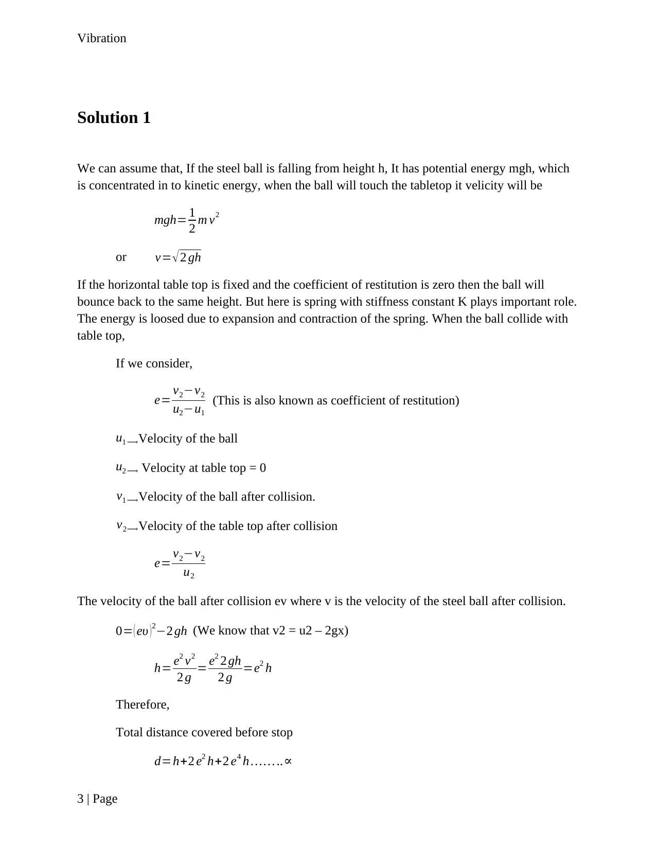
We can assume that, If the steel ball is falling from height h, It has potential energy mgh, which
is concentrated in to kinetic energy, when the ball will touch the tabletop it velicity will be
mgh= 1
2 m v2
or v= √ 2 gh
If the horizontal table top is fixed and the coefficient of restitution is zero then the ball will
bounce back to the same height. But here is spring with stiffness constant K plays important role.
The energy is loosed due to expansion and contraction of the spring. When the ball collide with
table top,
If we consider,
e= v2−v2
u2−u1
(This is also known as coefficient of restitution)
u1 ⟶Velocity of the ball
u2 ⟶ Velocity at table top = 0
v1 ⟶Velocity of the ball after collision.
v2⟶Velocity of the table top after collision
e= v2−v2
u2
The velocity of the ball after collision ev where v is the velocity of the steel ball after collision.
0= ( eυ )2−2 gh (We know that v2 = u2 – 2gx)
h= e2 ν2
2 g = e2 2 gh
2 g =e2 h
Therefore,
Total distance covered before stop
d=h+2 e2 h+2 e4 h … … ..∝
3 | Page
⊘ This is a preview!⊘
Do you want full access?
Subscribe today to unlock all pages.

Trusted by 1+ million students worldwide
Vibration
¿ 1+e2
1−e2 h
The velocity of the ball decreases due to the loss of energy because of the sping.
Solution 2
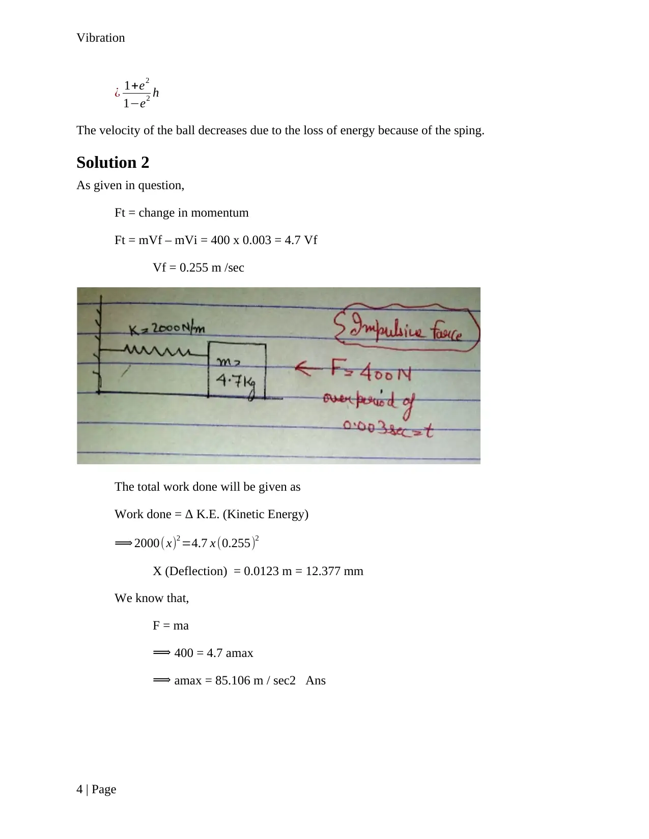
As given in question,
Ft = change in momentum
Ft = mVf – mVi = 400 x 0.003 = 4.7 Vf
Vf = 0.255 m /sec
The total work done will be given as
Work done = Δ K.E. (Kinetic Energy)
⟹ 2000( x)2 =4.7 x (0.255)2
X (Deflection) = 0.0123 m = 12.377 mm
We know that,
F = ma
⟹ 400 = 4.7 amax
⟹ amax = 85.106 m / sec2 Ans
4 | Page
Paraphrase This Document
Need a fresh take? Get an instant paraphrase of this document with our AI Paraphraser
Vibration
Solution 3
As given in question,
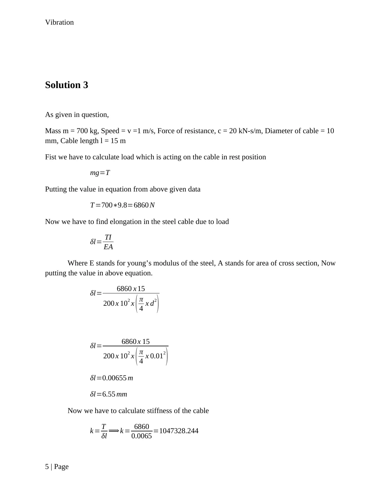
Mass m = 700 kg, Speed = v =1 m/s, Force of resistance, c = 20 kN-s/m, Diameter of cable = 10
mm, Cable length l = 15 m
Fist we have to calculate load which is acting on the cable in rest position
mg=T
Putting the value in equation from above given data
T =700∗9.8=6860 N
Now we have to find elongation in the steel cable due to load
δl= TI
EA
Where E stands for young’s modulus of the steel, A stands for area of cross section, Now
putting the value in above equation.
δl= 6860 x 15
200 x 102 x ( π
4 x d2
)
δl= 6860 x 15
200 x 102 x ( π
4 x 0.012
)
δl=0.00655 m
δl=6.55 mm
Now we have to calculate stiffness of the cable
k = T
δl ⟹ k = 6860
0.0065 =1047328.244
5 | Page
Vibration
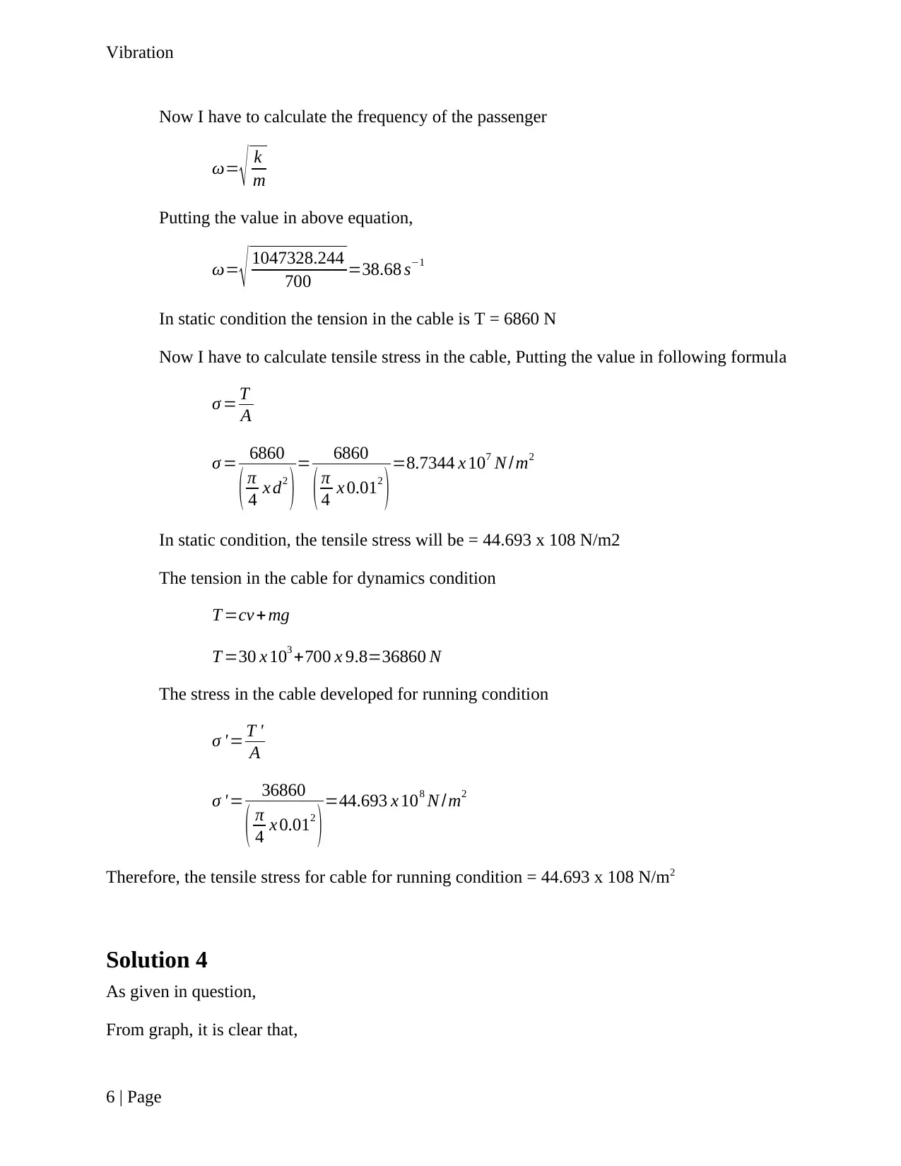
Now I have to calculate the frequency of the passenger
ω= √ k
m
Putting the value in above equation,
ω= √ 1047328.244
700 =38.68 s−1
In static condition the tension in the cable is T = 6860 N
Now I have to calculate tensile stress in the cable, Putting the value in following formula
σ = T
A
σ = 6860
( π
4 x d2
)= 6860
( π
4 x 0.012
)=8.7344 x 10⁷ N /m2
In static condition, the tensile stress will be = 44.693 x 10⁸ N/m2
The tension in the cable for dynamics condition
T =cv + mg
T =30 x 103 +700 x 9.8=36860 N
The stress in the cable developed for running condition
σ ' = T '
A
σ ' = 36860
( π
4 x 0.012
)=44.693 x 10⁸ N /m2
Therefore, the tensile stress for cable for running condition = 44.693 x 10⁸ N/m2
Solution 4
As given in question,
From graph, it is clear that,
6 | Page
⊘ This is a preview!⊘
Do you want full access?
Subscribe today to unlock all pages.

Trusted by 1+ million students worldwide
Vibration
Acceleration for 1st four second = 1.4 / 4 = 0.35 m/sec2
Deceleration for last four second = 1.4/4 = 0.35 m/sec2
Distance covered in 1st four second = ½ * 0.35 * 4*4 = 11.2
Distance in next 4 second at the speed of 1.4 m/sec = 1.5 * 4 = 5.6 m
Distance covered in last four second = 1.4*1.4 / (2 * 0.35) = 2.8
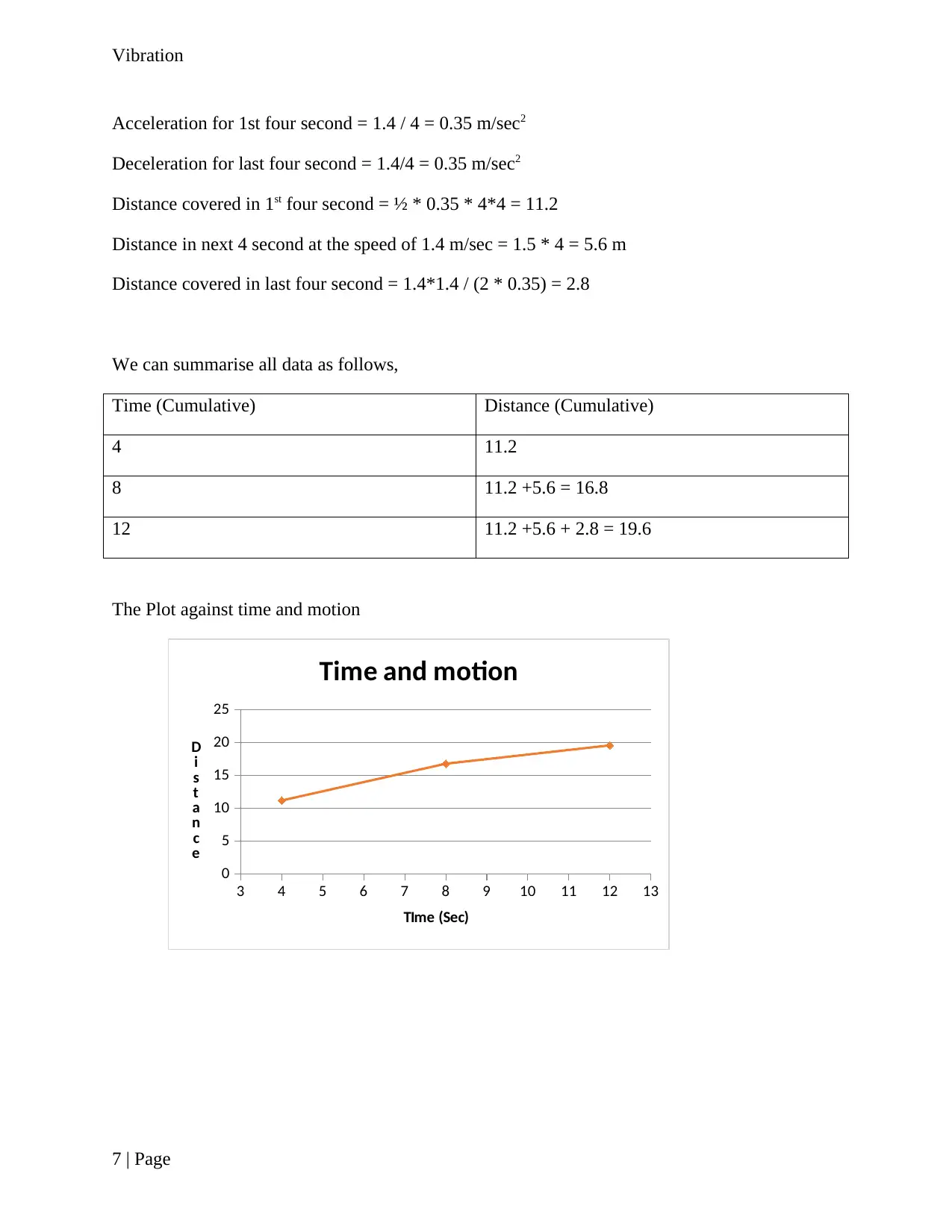
We can summarise all data as follows,
Time (Cumulative) Distance (Cumulative)
4 11.2
8 11.2 +5.6 = 16.8
12 11.2 +5.6 + 2.8 = 19.6
The Plot against time and motion
3 4 5 6 7 8 9 10 11 12 13
0
5
10
15
20
25
Time and motion
TIme (Sec)
D
i
s
t
a
n
c
e
7 | Page
Paraphrase This Document
Need a fresh take? Get an instant paraphrase of this document with our AI Paraphraser
Vibration
Solution 5
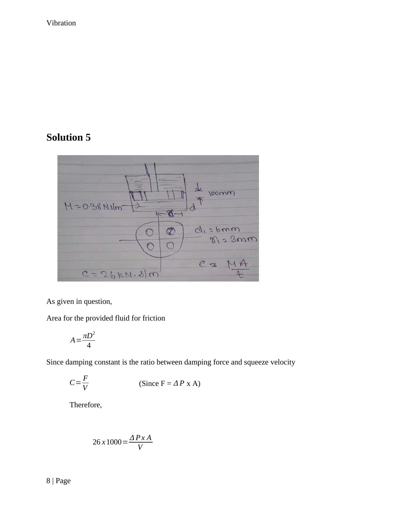
As given in question,
Area for the provided fluid for friction
A= πD2
4
Since damping constant is the ratio between damping force and squeeze velocity
C= F
V (Since F = Δ P x A)
Therefore,
26 x 1000= Δ P x A
V
8 | Page
Solution 5
As given in question,
Area for the provided fluid for friction
A= πD2
4
Since damping constant is the ratio between damping force and squeeze velocity
C= F
V (Since F = Δ P x A)
Therefore,
26 x 1000= Δ P x A
V
8 | Page
Vibration
26 x 1000= Δ P x π x D2
V x 4
v= Δ P x π x D2
26 x 1000 x 4 …..(i)
As given in question
Laminar velocity = v= d2 Δ P
32 μ L
Equation Both the equation we get
v= Δ P x π x D2
26 x 1000 x 4 = d2 Δ P
32 μ L Solving for D2
D2= d2
32 μ L
26 x 1000 x 4
x 3.14
D2= 0.062
32 x 0.38 x 0.1 x 26 x 1000 x 4
x 3.14
D2=98.055
D=9.9 m Ans
Solution 6
As given in question,
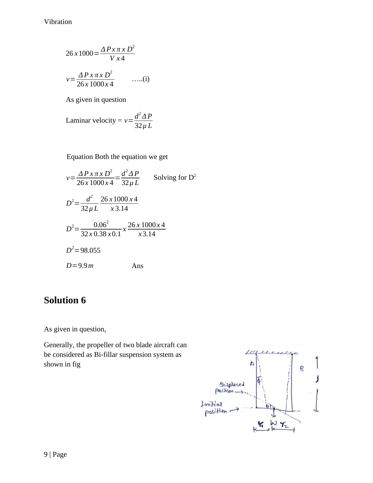
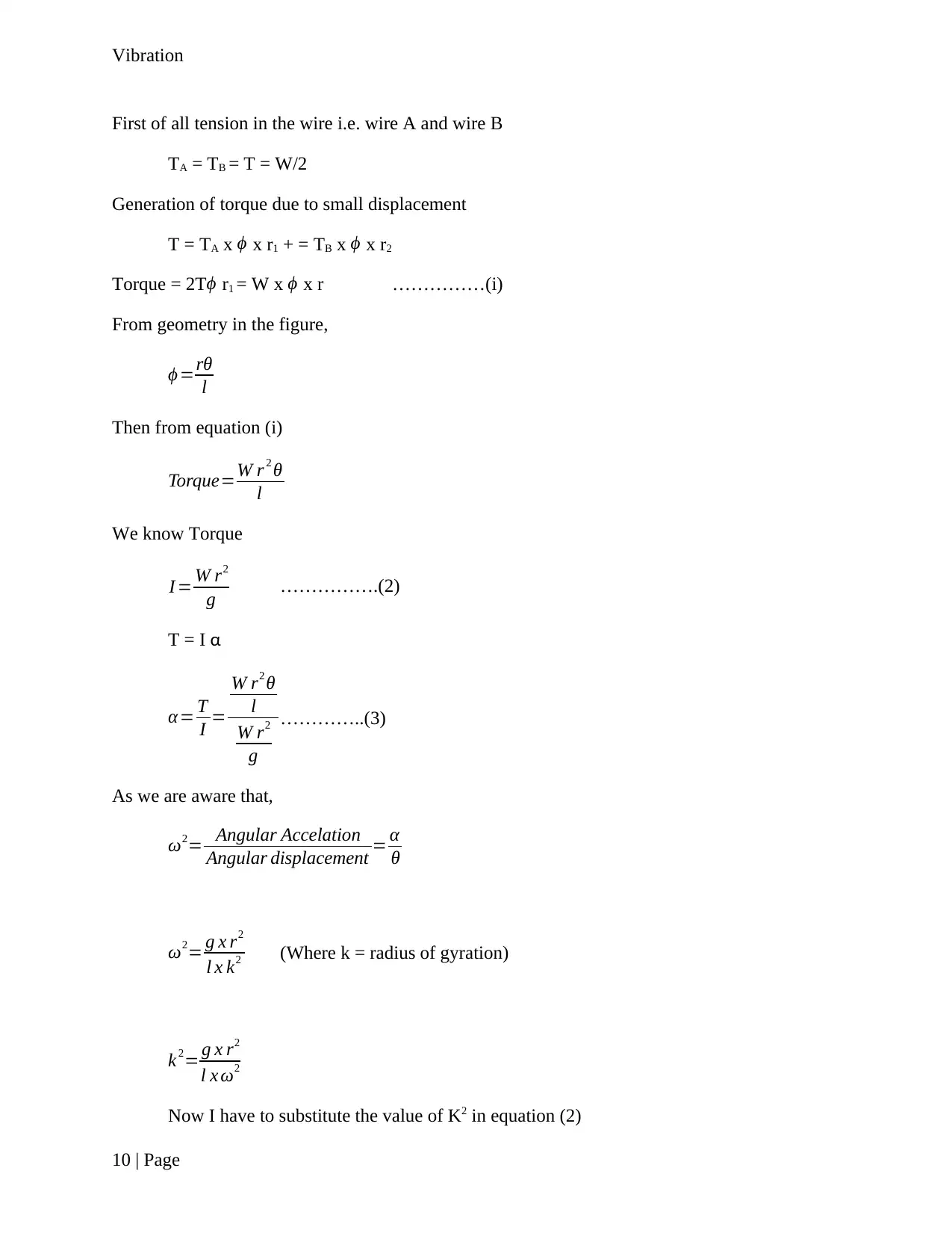
Generally, the propeller of two blade aircraft can
be considered as Bi-fillar suspension system as
shown in fig
9 | Page
⊘ This is a preview!⊘
Do you want full access?
Subscribe today to unlock all pages.

Trusted by 1+ million students worldwide
Vibration
First of all tension in the wire i.e. wire A and wire B
TA = TB = T = W/2
Generation of torque due to small displacement
T = TA x ϕ x r1 + = TB x ϕ x r2
Torque = 2Tϕ r1 = W x ϕ x r ……………(i)
From geometry in the figure,
ϕ =rθ
l
Then from equation (i)
Torque=W r 2 θ
l
We know Torque
I = W r2
g …………….(2)
T = I α
α= T
I =
W r2 θ
l
W r2
g
…………..(3)
As we are aware that,
ω2= Angular Accelation
Angular displacement = α
θ
ω2= g x r2
l x k2 (Where k = radius of gyration)
k 2= g x r2
l x ω2
Now I have to substitute the value of K2 in equation (2)
10 | Page
Paraphrase This Document
Need a fresh take? Get an instant paraphrase of this document with our AI Paraphraser
Vibration
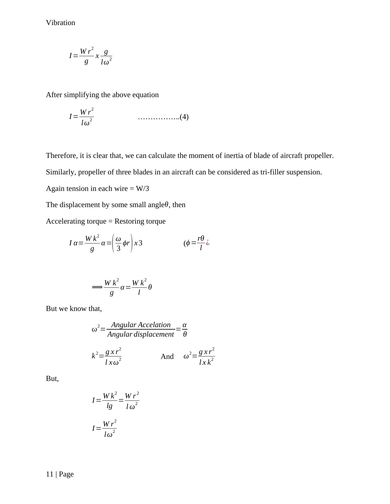
I = W r2
g x g
lω2
After simplifying the above equation
I = W r2
lω2 ……………..(4)
Therefore, it is clear that, we can calculate the moment of inertia of blade of aircraft propeller.
Similarly, propeller of three blades in an aircraft can be considered as tri-filler suspension.
Again tension in each wire = W/3
The displacement by some small angleθ, then
Accelerating torque = Restoring torque
I α= W k2
g α =( ω
3 ϕr ) x 3 (ϕ =rθ
l ¿
⟹ W k2
g α=W k2
l θ
But we know that,
ω2= Angular Accelation
Angular displacement = α
θ
k 2= g x r2
l x ω2 And ω2= g x r2
l x k2
But,
I = W k2
lg =W r 2
l ω2
I = W r2
lω2
11 | Page
I = W r2
g x g
lω2
After simplifying the above equation
I = W r2
lω2 ……………..(4)
Therefore, it is clear that, we can calculate the moment of inertia of blade of aircraft propeller.
Similarly, propeller of three blades in an aircraft can be considered as tri-filler suspension.
Again tension in each wire = W/3
The displacement by some small angleθ, then
Accelerating torque = Restoring torque
I α= W k2
g α =( ω
3 ϕr ) x 3 (ϕ =rθ
l ¿
⟹ W k2
g α=W k2
l θ
But we know that,
ω2= Angular Accelation
Angular displacement = α
θ
k 2= g x r2
l x ω2 And ω2= g x r2
l x k2
But,
I = W k2
lg =W r 2
l ω2
I = W r2
lω2
11 | Page
Vibration
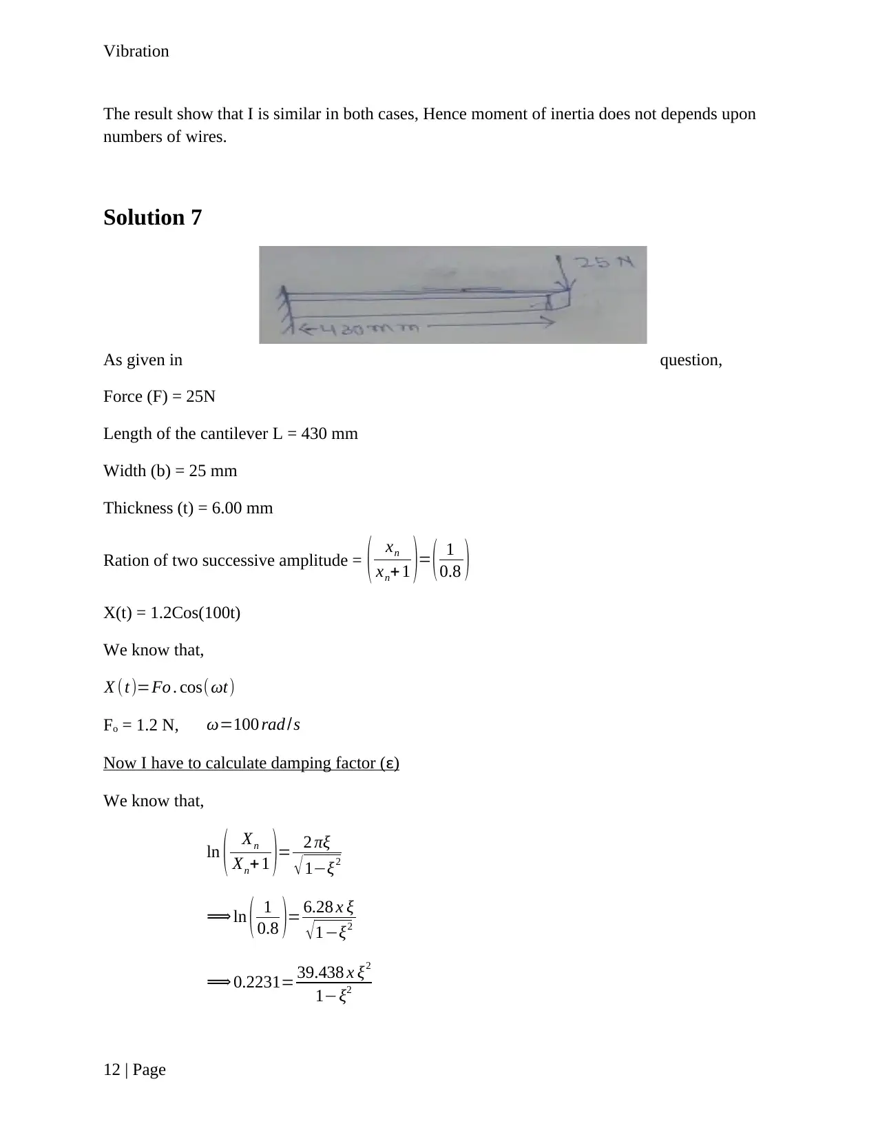
The result show that I is similar in both cases, Hence moment of inertia does not depends upon
numbers of wires.
Solution 7
As given in question,
Force (F) = 25N
Length of the cantilever L = 430 mm
Width (b) = 25 mm
Thickness (t) = 6.00 mm
Ration of two successive amplitude = ( xn
xn+1 )= ( 1
0.8 )
X(t) = 1.2Cos(100t)
We know that,
X (t)=Fo . cos(ωt)
Fo = 1.2 N, ω=100 rad /s
Now I have to calculate damping factor (ε)
We know that,
ln ( Xn
Xn+ 1 )= 2 πξ
√ 1−ξ2
⟹ ln ( 1
0.8 )= 6.28 x ξ
√1−ξ2
⟹ 0.2231= 39.438 x ξ2
1−ξ2
12 | Page
⊘ This is a preview!⊘
Do you want full access?
Subscribe today to unlock all pages.

Trusted by 1+ million students worldwide
1 out of 16
Your All-in-One AI-Powered Toolkit for Academic Success.
+13062052269
info@desklib.com
Available 24*7 on WhatsApp / Email
![[object Object]](/_next/static/media/star-bottom.7253800d.svg)
Unlock your academic potential
Copyright © 2020–2025 A2Z Services. All Rights Reserved. Developed and managed by ZUCOL.
