Sainath Punukollu - CDR Career Episode 1: Fiber Link Design Project
VerifiedAdded on 2020/02/24
|9
|1763
|243
Report
AI Summary
This report is a Competency Demonstration Report (CDR) detailing the design and simulation of a fiber optic communication system. The project focused on enhancing the capacity and quality of telecommunications by designing a cost-effective 40 Gbps optical fiber link. The student's work included designing a single fiber link, simulating it using Rsoft-OptSim software, applying Eye Diagram techniques, developing a WDM system with eight channels, and analyzing its performance. Key aspects involved understanding the theory, applying engineering knowledge, and collaborative teamwork to overcome challenges, such as optimizing the WDM system for error-free signal transmission. The project's success was evaluated through the design of the fiber link, the analysis of the bit rate and non-linear effects, and the optimization of the optical fiber performance with EDFA gains.

Competency Demonstration Report (CDR)
Career Episode 1
Sainath Punukollu
Career Episode 1
Sainath Punukollu
Paraphrase This Document
Need a fresh take? Get an instant paraphrase of this document with our AI Paraphraser
CE 1.1: Project Introduction
Name of the Project : Designing of Data and Voice Communication using Fiber
Link
Geographical Location : [Please Fill]
Project Duration : [Please Fill]
Organization : [Please Fill]
Position in the Project : Team Member
CE 1.2: Project Background
CE 1.2.1: Characteristics of the Project
The increased traffic in the telecommunication system has forced foe the development of
high capacity and speed of telecommunication system while providing extreme support and
quality to the customers. I have observed that maximum numbers of telecommunication channels
are developed with optical fibers. Due to the high implementation and maintenance cost of the
optical fibers, several countries suffer from slow and low quality communication system.
Therefore, I have observed that it is essential to identify an alternative solution to the optical
fiber communication line for providing the reliable, high quality, high speed telecommunication
system with low price. Therefore, I undertook this particular project for the enhancing the
capacity of the existing optical fiber network for simulating and improving the quality, capacity
and speed of communication.
Page 1 of 9
CE 1.2.2: Objectives developed for project
With the aim of improving the capacity and quality of the telecommunication system I
have simulated the optical fiber for meeting the demand of capacity. In this project, I have
simulated ad designed a cost effective and easy solution for simulating the 40 Gbps optical fiber
link. I have made my vital goal is to establish a low cost and high quality fiber link system that
could enhance the overall quality and speed of the communication. In order to complete the
undertaken project, I have highlighted the different objectives in the section below:
To develop the basic design for the single fiber link;
To analyze the fiber link using Rsoft-OptSim commercial software;
To apply the technique of Eye Diagram in order to access the ability of data
handling of the telecommunication system;
To develop the WDM System for enabling communication between links;
To analyze and evaluate the performance of the developed WDM system;
CE 1.2.3: My area of work
I have the major responsibility of developing the appropriate design of the single link
optical fiber in the telecommunication system. Before establishing the network, I have identified
the hardware element that was required for the completion of the optical fiber communication
network. I have learned the application of commercial software Rsoft-OptSim for simulating the
proposed network for this project. Throughout the project, I have worked towards the
development of cost efficient and high performance optical network channel for the customers.
CE 1.2.4: Project Group
Page 2 of 9
⊘ This is a preview!⊘
Do you want full access?
Subscribe today to unlock all pages.

Trusted by 1+ million students worldwide
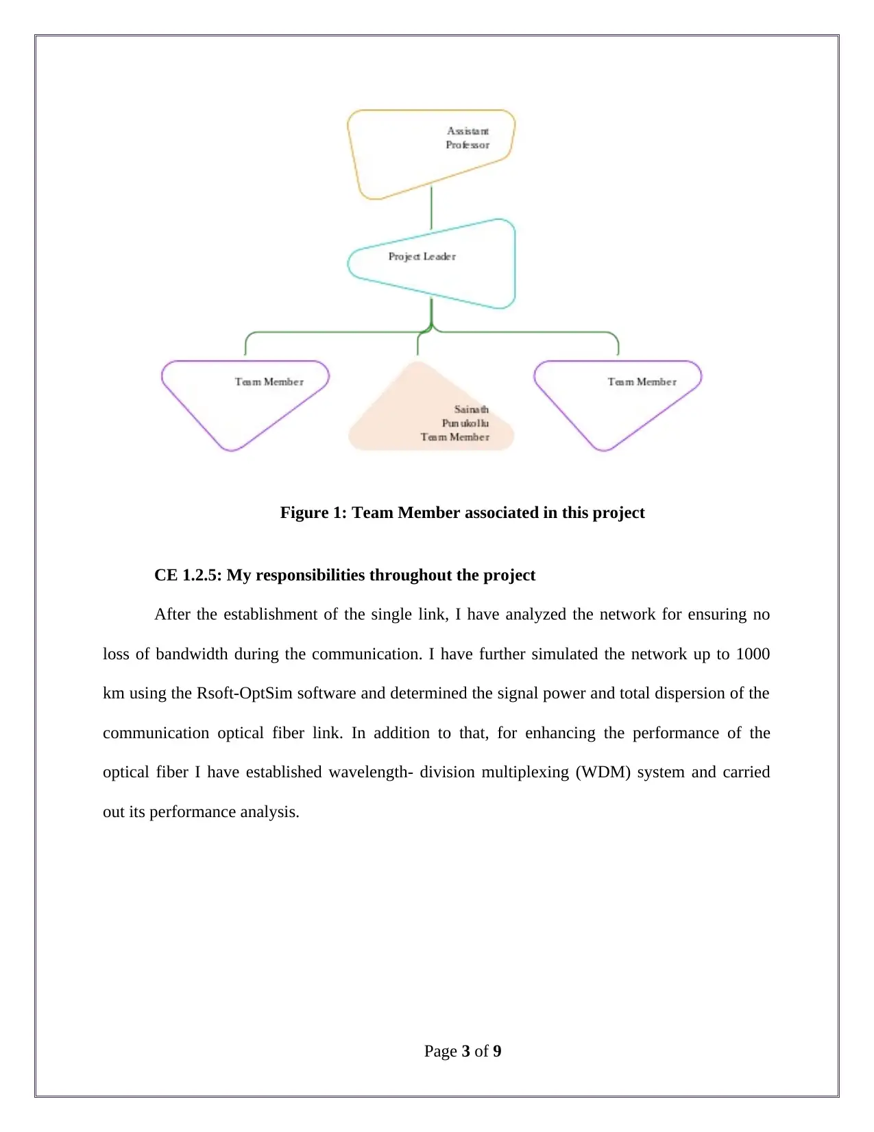
Figure 1: Team Member associated in this project
CE 1.2.5: My responsibilities throughout the project
After the establishment of the single link, I have analyzed the network for ensuring no
loss of bandwidth during the communication. I have further simulated the network up to 1000
km using the Rsoft-OptSim software and determined the signal power and total dispersion of the
communication optical fiber link. In addition to that, for enhancing the performance of the
optical fiber I have established wavelength- division multiplexing (WDM) system and carried
out its performance analysis.
Page 3 of 9
Paraphrase This Document
Need a fresh take? Get an instant paraphrase of this document with our AI Paraphraser
CE 1.3: Distinctive Activity
CE 1.3.1: Comprehending the Theory of the project
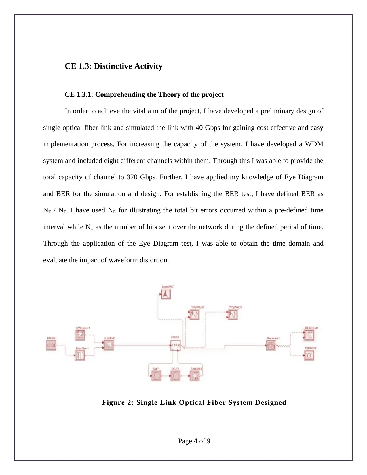
In order to achieve the vital aim of the project, I have developed a preliminary design of
single optical fiber link and simulated the link with 40 Gbps for gaining cost effective and easy
implementation process. For increasing the capacity of the system, I have developed a WDM
system and included eight different channels within them. Through this I was able to provide the
total capacity of channel to 320 Gbps. Further, I have applied my knowledge of Eye Diagram
and BER for the simulation and design. For establishing the BER test, I have defined BER as
NE / NT. I have used NE for illustrating the total bit errors occurred within a pre-defined time
interval while NT as the number of bits sent over the network during the defined period of time.
Through the application of the Eye Diagram test, I was able to obtain the time domain and
evaluate the impact of waveform distortion.
Figure 2: Single Link Optical Fiber System Designed
Page 4 of 9
CE 1.3.2: Engineering Knowledge and Skills applied in the project
The significant work required in this project was the establishment of the WDM system
for providing high transmission capacity. I have integrated total number of 8 channels and kept 2
nm of space between them. I have further chosen wavelength of 1540 nm to 1560 nm for
providing low loss window for transmission. In order to eliminate any possible additional noise
and symbol interference within the communication, I have kept the spacing to 2 nm. In this
particular system, I have used demultiplexer before the use of receivers and multiplexers after
the attachment of the source along with the single link. Further I have kept the gain of EDFA to
16 dB. Nevertheless, I have used the filter at various level of DEMUX for separating the
transmitted trapezoidal signal. Therefore, I have set the frequency of the filter as the applicable
wavelength for the channel. Through the particular design I was able to determine the
unavoidable attenuation and dispersion after 1000 km of transmission.
CE 1.3.3: Accomplishment and Task Performed
In this project, I have used the CW (Continuous Wave) laser having 0.95 mW peak
power as the power source bit generator, optical fibres, obtival simulators, electrical modulator
and electrical signal generator. For designing thee link, I have used wavelenght of 1550 nm as I
have identified minimum amunt of wavelenght loss at this point.
Page 5 of 9
⊘ This is a preview!⊘
Do you want full access?
Subscribe today to unlock all pages.

Trusted by 1+ million students worldwide
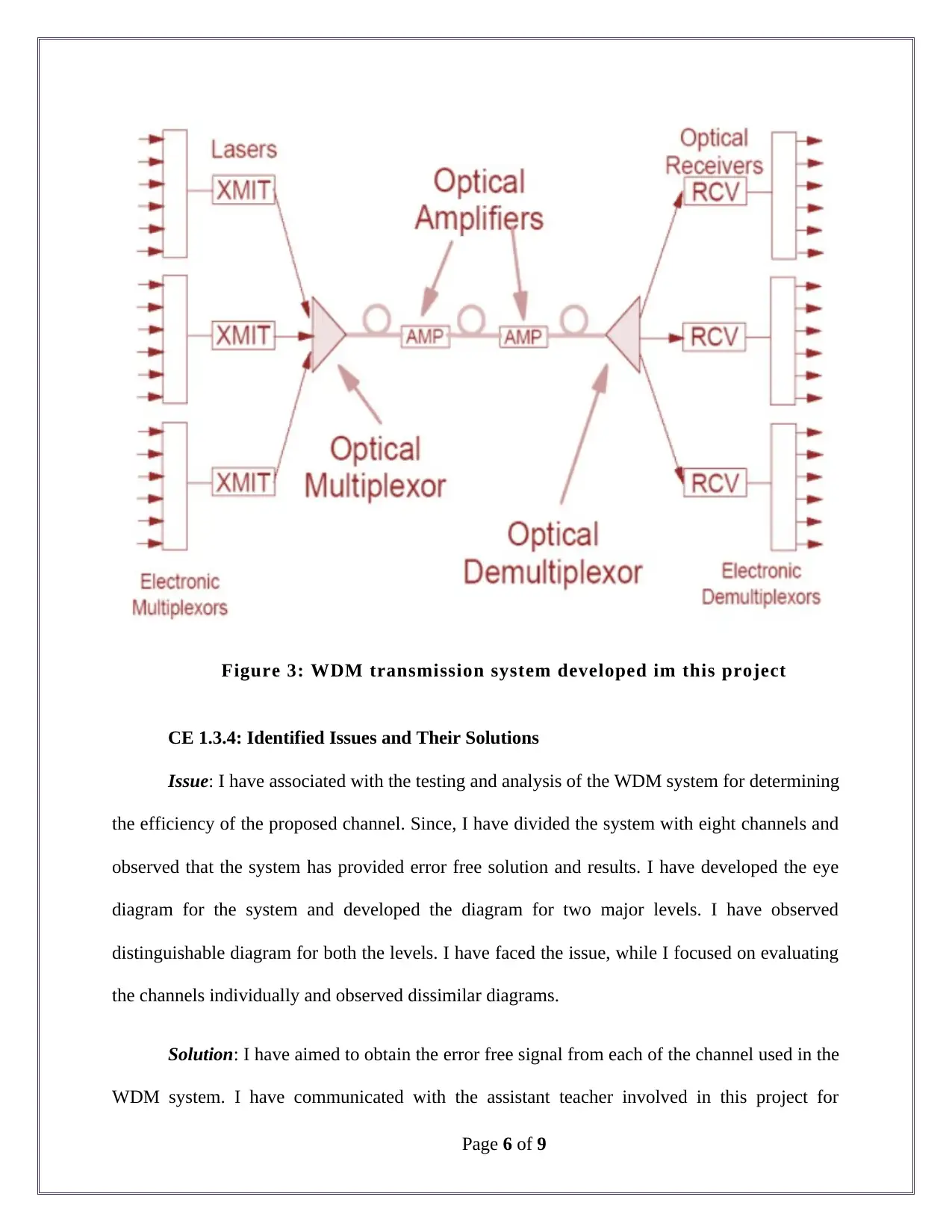
Figure 3: WDM transmission system developed im this project
CE 1.3.4: Identified Issues and Their Solutions
Issue: I have associated with the testing and analysis of the WDM system for determining
the efficiency of the proposed channel. Since, I have divided the system with eight channels and
observed that the system has provided error free solution and results. I have developed the eye
diagram for the system and developed the diagram for two major levels. I have observed
distinguishable diagram for both the levels. I have faced the issue, while I focused on evaluating
the channels individually and observed dissimilar diagrams.
Solution: I have aimed to obtain the error free signal from each of the channel used in the
WDM system. I have communicated with the assistant teacher involved in this project for
Page 6 of 9
Paraphrase This Document
Need a fresh take? Get an instant paraphrase of this document with our AI Paraphraser
detailed guidance. Upon his direction, I have considered one channel 1542 for determining the
analysis of the output. For this I have used demultiplexer at the lower end of the channel and
dropped the other entire channel during evaluation. Through this I was able to obtain two similar
eye diagram for two different decision levels.
CE 1.3.5: Plan for producing creative and innovative work
I have aimed to provide innovative and creative work during the design and
implementation of the link for enhanced performance. I have worked intensively for the design
of the single link. I have selected the application of CW laser due to noise free solution. In
addition to that, I have eliminated the application of internal modulator and used eternal
modulator for avoiding the jitter noise. For compensating the dispersion, I have used
combination of Corning Vascade-S1000 and Corning-SMF28-1550. Further, I have applied
SMF-28 for transmitting over a certain distance and DCF (VascadeS1000 Dispersion
Compensated Fiber) for the extended distance for communication. Through this ii was able to
obtain negligible dispersion over the optical fiber link. I have further used EDFA (Erbium Doped
Fiber Amplifier) as the optical amplifier. Through this I was able t reduce the non-linear effect of
the amplifier with 15.8 dB of gain.
CE 1.3.6: Collaborative work
I have worked in this project for the design and simulation of the Fiber Link that has been
used for enhancing the bandwidth and speed of the data transfer through the developed
communication optical channel. I have ensured regular communication with the other team
members and the assistant professor who have guided me throughout the project. In addition to
that, I have discussed any issue or problem during the establishment of the optical network. With
Page 7 of 9
the application of collaborative work, I have successfully completed the project within the
deadline.
CE 1.4: Project Review
CE 1.4.1: Project Overview
Overview: I have efficiently carried out the simulation and design of the communication
line. After the completion of the simulation, I have observed that the application of the proposed
design of the optical fiber link, the bit rate and the non-linearly effects were much higher.
Through the developed system I was able to optimize the production and performance of the
optical fiber with 16 dB and 15 dB gain. The undertaken project has been a success.
Output: After conducting the testing of the fiber link system, I have observed that the
non-linearity effects and the fiber dispersion significant impacted the high bit rate of the system
upto 40 Gbps. The error free of the data transmission has occurred when I have successful in
accurately defining the EDFA gain. In addition to that, inputting high amount of gain has
resulted in the production of the non-linearity effect. Apart from the application of WDM has
allowed me to upgrade the capacity of the transmission to 320 Gbps.
CE 1.4.2: My contribution to work
In spite of working as a team member for the development and implementation of the
Fiber link Design, I have focused on delivering low cost yet highly efficient communication
system with optical fiber. With the application of proficient knowledge and understanding about
the optical fiber properties and communication channels, I was able to achieve considerable
success during this project.
Page 8 of 9
⊘ This is a preview!⊘
Do you want full access?
Subscribe today to unlock all pages.

Trusted by 1+ million students worldwide
1 out of 9
Related Documents
Your All-in-One AI-Powered Toolkit for Academic Success.
+13062052269
info@desklib.com
Available 24*7 on WhatsApp / Email
![[object Object]](/_next/static/media/star-bottom.7253800d.svg)
Unlock your academic potential
Copyright © 2020–2025 A2Z Services. All Rights Reserved. Developed and managed by ZUCOL.


