ITECH7201: Software Engineering - Individual Contribution Report Lab 8
VerifiedAdded on 2022/11/15
|10
|1902
|92
Project
AI Summary
This document is an individual contribution report for a Software Engineering project, specifically focusing on Lab 8 of a Maze Game developed in Java. The report details the functionalities implemented, including the execution of the Command Pattern, the creation of classes like DungeonMaster and CommandHandler, and the use of Hashtables for command aliases. It covers the implementation of "look" commands (location and exit), maze mesh production using a MazeMeshGenerator script, and the application of the Depth-first search algorithm for maze generation. The report includes class and sequence diagrams illustrating the project's structure and item management, respectively. The student's contribution involved modifying and adding code for the functions of Lab 8, including the help feature, pick and drop items, and buy/sell features. The report also acknowledges the contributions of the team, such as the welcome, move, lock/unlock, and quit game features, and the collaborative effort in developing the map and integrating the individual contributions.

SOFTWARE ENGINEERING
Individual Contribution Report
Individual Contribution Report
Paraphrase This Document
Need a fresh take? Get an instant paraphrase of this document with our AI Paraphraser
1
Table of Contents
Introduction......................................................................................................................................2
Functionalities..................................................................................................................................2
Implementations..............................................................................................................................4
Class diagrams for Lab 8.................................................................................................................6
Sequence diagram............................................................................................................................7
Contribution statement.....................................................................................................................8
2
Introduction
Our task can be easier should we assume that the maze is made of squares. Every
particular square would be occupied by a wall or an opening. It is only through the openings that
the turtle can successfully go out from each square. The implication is that the turtle will have to
proceed to use another way whenever it finds itself facing a wall. A systematic procedure can be
deployed by the turtle to successfully exit the maze (Meiliana, Septian, Alianto, Daniel & Gaol,
2017). The process is highlighted below.
Based on the first position of the turtle, the turtle can decide to proceed south and then
continuously repeat the procedure.
Should the Southern path be blocked, the turtle will attempt to move northward and
repeat the procedure.
Should the Northern path be blocked, then the topic will try the Eastern path and repeat
the process.
Should the Eastern path be blocked, then the Western path will be considered with the
same iterative procedure.
Functionalities
In lab 8, the further functionalities will take place:
Execution of Command Pattern
Then DungeonMaster class has a very messy look. We proceed through the creation of
abstract class for signifying the overall command. We have to create another interface for
Command. We also need the CommandResponse class to provide a reply to the player as each
command gets processed. We have to put down a for move command and another command for
⊘ This is a preview!⊘
Do you want full access?
Subscribe today to unlock all pages.

Trusted by 1+ million students worldwide
3
exiting. Prior to changing DungeonMaster, an extra class gets introduced for the monitoring of
very command that is available. Another class known as CommandHandler should be created.
For a every command class to have a maintained Hashtable, with label indexing, it looks
good because:
It is possible for aliases to be programmed for every command (such as move and go
referring a particular command. With the development of the new command classes, we simply
indicate the class and add it to hashtable with a label to make it function effectively.
A problem could be observed with the invocation of the move command with ArrayLIst
Parsed Input argument staying without anything. A little coding can be utilized in simply
carrying out a MoveCommand defense. The received information does not still look good
enough in the event of any movement when the game is on. The presentation of outcomes will
then be adjusted. I being with development of ToString Location method. (Nagakura, 2008)
Look Command
Before executing look command, the behaviour through a user story should be stated.
Three “look” stories are observed in the first RAD.
Look Character
Look Location
Look Item
It is possible to come up with a fourth alternative: “look exit”. Considering that the
characters or objects that won’t be playing are not yet introduced, we will place emphasis on exit
and location in the time being.
Look Location – a player provides absent argument for the look command and describes
the current location of the player for the system to return.
Paraphrase This Document
Need a fresh take? Get an instant paraphrase of this document with our AI Paraphraser
4
Look Exit – a player provides the look command through the argument so that there is a
match between the argument and exit.
The 2 user stories are related with a possibility of being completed concurrently by
developing Look Command. For it to operate, a new approach should be introduced in the
ContainsExit Location. Currently the CommandHandler can contain the LookCommand.
Implementations
Maze Mesh Production
Considering that the underlying data of the maze have been properly produced, we can
now carry out mesh construction with the aid of the data.
Generate another script with MazeMesh Generator name. This is equivalent to the
resulting MazeDataGenerator in the logic encapsulation for data generation. The
generated mesh logic will be inside the MazeMeshGenerator and used by Maze
Constructor for conducting the generation of maze mesh.
Alternatively, it will finally comprise the logic required for mesh generation. Firstly, the
creation of textured quad will be carried out for demonstration purpose after which the
code will be adjusted for the whole maze generation. For this to be achieved, some minor
changes will be done inside the editor prior to using the code.
You will need to first link materials with the application to generate the mesh.
Pick the graphics folders that is located at the under part of the project window, after
which you pick the controller that can be found in the upper side of the order window to
allow us observe the Maze Constructor component at the Inspector.
In the graphics folder, transfer materials to the material slots for the Maze constructor.
Use Material 1 floor-mat as well as the wall-mat for Material 2. You can then start to
proceed based on the slots. (Prakash Shrivastava, 2012)
In the process of doing the Inspector activity, you should also add the Generated Tag:
Pick Tag menu at the upper side of Inspector and indicate Add Tag. As the meshes are
being generated, every identification will be assigned a tag.
5
Algorithm for Developing a Maze Game
The Depth-first search algorithm is a good algorithm for generating the maze. The idea is
very simple and easy to execute idea based on the recurrent or stack technique. There is a
relationship between Depth First Search for a tree and for graphs. There are however, few
differences as Depth Search for graph could have cycles, while for trees cannot have. The cycles
mean we can get to a specific node that we have been before. To avoid a process where we don’t
get involved in processing a specific node again, we can utilize the Boolean array. The space as
well as time analysis for DFS is not the same as a result of the area for application. Theoretically
speaking, you can use DFS basically for searching the full graph, which leads to time wastage. In
these instances, we also use space for cases that are most difficult for storage of vertices stack for
the current path of search and the vertices set that are already visited. Thus, in this setting, time
and space bounds are related to the breadth-first search. Choosing which of the algorithm will be
used first does not depend on complexity but on the ordering properties of the various vertex that
the 2 algorithms produce.
Basically, you should start randomly from any of the points and keep digging paths
across the 4 ways (right, left, down, up) until you cannot find any other direction. Should you get
stuck, keep going back until you find yourself in a space that is open. You can then proceed to
continue your digging from there. You just have to continue carrying out these. (WANG, WANG
& LIU, 2009)
Steps
1. Create a two dimensional array int with odd size for the row and column. Paths signified
by orange cell are coded with 0 and walls signified by black cells are coded with 1.
2. General odd row and col numbers. Adjust cell to zero. Utilize the row and col variables
for present location monitoring.
3. Choose a random direction (right, left, down or up) that you want to proceed to. You can
always move in line with 2 cells. The picture above shows the downwards movement of
the present cell. You should look out for some factors when you are moving. Firstly,
confirm that the next 2 cells in the forward direction will not be inside the maze.
⊘ This is a preview!⊘
Do you want full access?
Subscribe today to unlock all pages.

Trusted by 1+ million students worldwide
6
Class diagrams for Lab 8
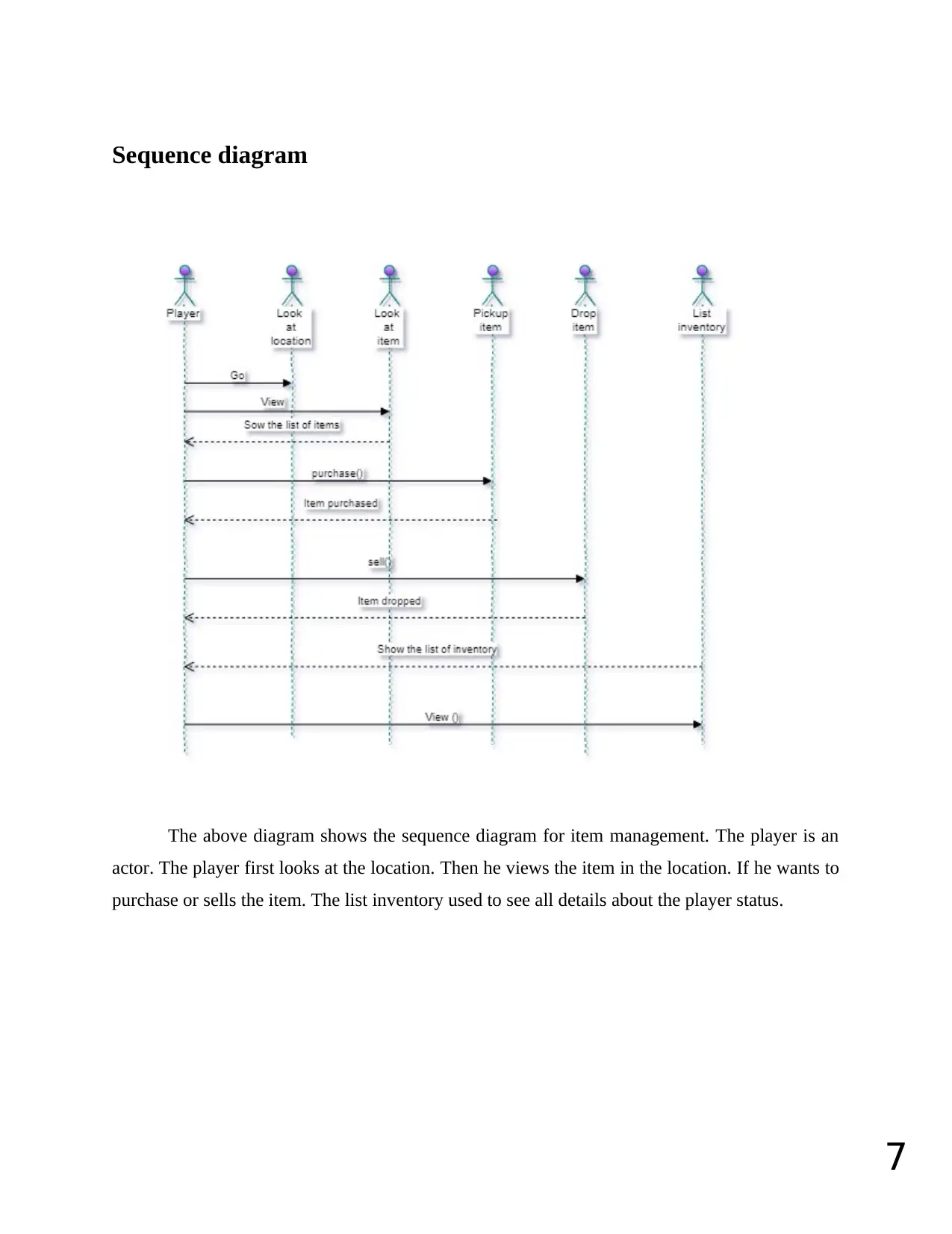
In the below-given figure, the classes are arranged as a group. In the group, all the
elements have some common characteristics. There are three major elements are there in a class
diagram. And they are three rectangles. Here the first rectangle (top rectangle) contains the class
name. For example, consider the given figure Command Response and Locations are the class
names. And the second rectangle is termed as an attribute box. It contains different attributes.
And the last rectangle box contains the pieces of information about the different operations.
(Ņikiforova, Putintsev & Ahiļčenoka, 2016)
Paraphrase This Document
Need a fresh take? Get an instant paraphrase of this document with our AI Paraphraser
7
Sequence diagram
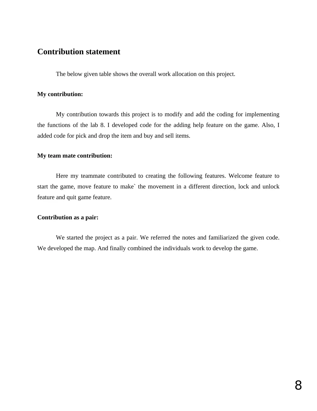
The above diagram shows the sequence diagram for item management. The player is an
actor. The player first looks at the location. Then he views the item in the location. If he wants to
purchase or sells the item. The list inventory used to see all details about the player status.
Sequence diagram
The above diagram shows the sequence diagram for item management. The player is an
actor. The player first looks at the location. Then he views the item in the location. If he wants to
purchase or sells the item. The list inventory used to see all details about the player status.
8
Contribution statement
The below given table shows the overall work allocation on this project.
My contribution:
My contribution towards this project is to modify and add the coding for implementing
the functions of the lab 8. I developed code for the adding help feature on the game. Also, I
added code for pick and drop the item and buy and sell items.
My team mate contribution:
Here my teammate contributed to creating the following features. Welcome feature to
start the game, move feature to make` the movement in a different direction, lock and unlock
feature and quit game feature.
Contribution as a pair:
We started the project as a pair. We referred the notes and familiarized the given code.
We developed the map. And finally combined the individuals work to develop the game.
⊘ This is a preview!⊘
Do you want full access?
Subscribe today to unlock all pages.

Trusted by 1+ million students worldwide
9
References
Meiliana, Septian, I., Alianto, R., Daniel, & Gaol, F. (2017). Automated Test Case Generation
from UML Activity Diagram and Sequence Diagram using Depth First Search
Algorithm. Procedia Computer Science, 116, 629-637. doi: 10.1016/j.procs.2017.10.029
Nagakura, D. (2008). Inconsistency of a Unit Root Test Against a Stochastic Unit Root
Process. SSRN Electronic Journal. doi: 10.2139/ssrn.1300074
Ņikiforova, O., Putintsev, S., & Ahiļčenoka, D. (2016). Analysis of Sequence Diagram Layout in
Advanced UML Modelling Tools. Applied Computer Systems, 19(1), 37-43. doi:
10.1515/acss-2016-0005
Prakash Shrivastava, D. (2012). Unit Test Case Design Metrics in Test Driven
Development. International Journal Of Software Engineering, 2(3), 43-48. doi:
10.5923/j.se.20120203.01
WANG, X., WANG, H., & LIU, C. (2009). Automatic Hierarchical Layout Algorithm for UML
Class Diagram. Journal Of Software, 20(6), 1487-1498. doi: 10.3724/sp.j.1001.2009.03417
1 out of 10
Related Documents
Your All-in-One AI-Powered Toolkit for Academic Success.
+13062052269
info@desklib.com
Available 24*7 on WhatsApp / Email
![[object Object]](/_next/static/media/star-bottom.7253800d.svg)
Unlock your academic potential
Copyright © 2020–2026 A2Z Services. All Rights Reserved. Developed and managed by ZUCOL.
