ITECH 7410 Software Engineering Methodologies: RMT System Report
VerifiedAdded on 2022/10/11
|13
|1902
|22
Report
AI Summary
This report presents a detailed analysis of a Real-time Money Transfer (RMT) system used in banking. It begins with an introduction to the system's functionality, including user authentication, money transfer processes, and real-time transactions. The core of the report includes an Entity Relationship Diagram (ERD) illustrating the database design, highlighting entities like users, customers, and login details, and their relationships. Data Flow Diagrams (DFDs) are provided to visualize the processes involved in money transfers, including data validation and SMS verification. Control specifications, including state machine diagrams and a process activation table, are used to describe the system's behavior. A comprehensive data dictionary outlines the data types, field sizes, and descriptions of database fields such as user ID, customer name, and transaction ID. The report concludes with a summary of the system's design and a bibliography of cited sources.
Running head: SOFTWARE ENGINEERING METHODOLOGIES
ITECH 7410- Software Engineering Methodologies
Name of Student-
Name of University-
Author’s Note-
ITECH 7410- Software Engineering Methodologies
Name of Student-
Name of University-
Author’s Note-
Paraphrase This Document
Need a fresh take? Get an instant paraphrase of this document with our AI Paraphraser
1SOFTWARE ENGINEERING METHODOLOGIES
Introduction
The case study considered for this report states the real time money transfer system for
the banking sectors (RMT). This system enables their customers to transfer their money from
one bank account to another in real time system. This system has identical flow to transfer the
money. The transfer of money usually takes place when the customer login in the system and
there has to be authenticate user to access the money transfer from one account to another. The
transfer of money has to be authenticate that is the total amount of money that is to be transferred
is to be less than or equal to the amount of money that is present in the account. All the banking
system that follows modern technologies provides this RMT service to their customers.
This report states different system diagram that includes entity relationship diagram, the
data flow diagrams and the data control diagrams associated with the real time system in banking
sectors. The control specifications for the system is included in this report along with a data
dictionary for the database system that is designed for the RMT system.
2SOFTWARE ENGINEERING METHODOLOGIES
Entity Relationship Diagram
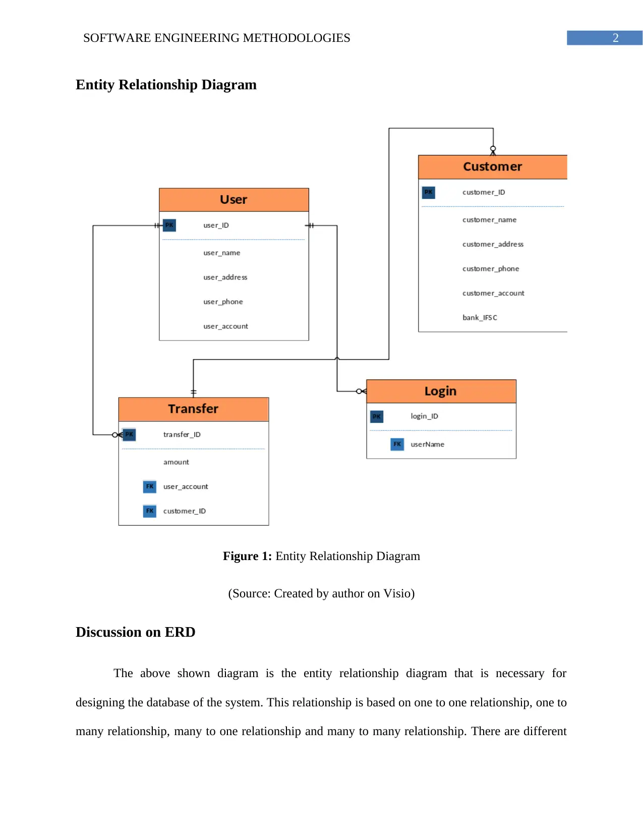
Figure 1: Entity Relationship Diagram
(Source: Created by author on Visio)
Discussion on ERD
The above shown diagram is the entity relationship diagram that is necessary for
designing the database of the system. This relationship is based on one to one relationship, one to
many relationship, many to one relationship and many to many relationship. There are different
⊘ This is a preview!⊘
Do you want full access?
Subscribe today to unlock all pages.

Trusted by 1+ million students worldwide
3SOFTWARE ENGINEERING METHODOLOGIES
entities shown in the diagram above that states the different database tables in the database. This
states all different tables that can be carried out for the system. Each of the entity has primary
keys that are uniquely identified for all the entities. The unique key must be unique and are to be
used for identifying uniquely in the database. There are foreign keys as well in the system. This
foreign key is the primary key for other different table and those establish the relationship
between the entities or in the tables. The user have user ids and they have user name, user
address, user phone and user account. This primary key of this entity is the user id which is
uniquely identified in the system. The customer have the customer_id as the unique primary key
and the login entity includes the login id as the primary key of the system.
Data and Control Flow Diagrams
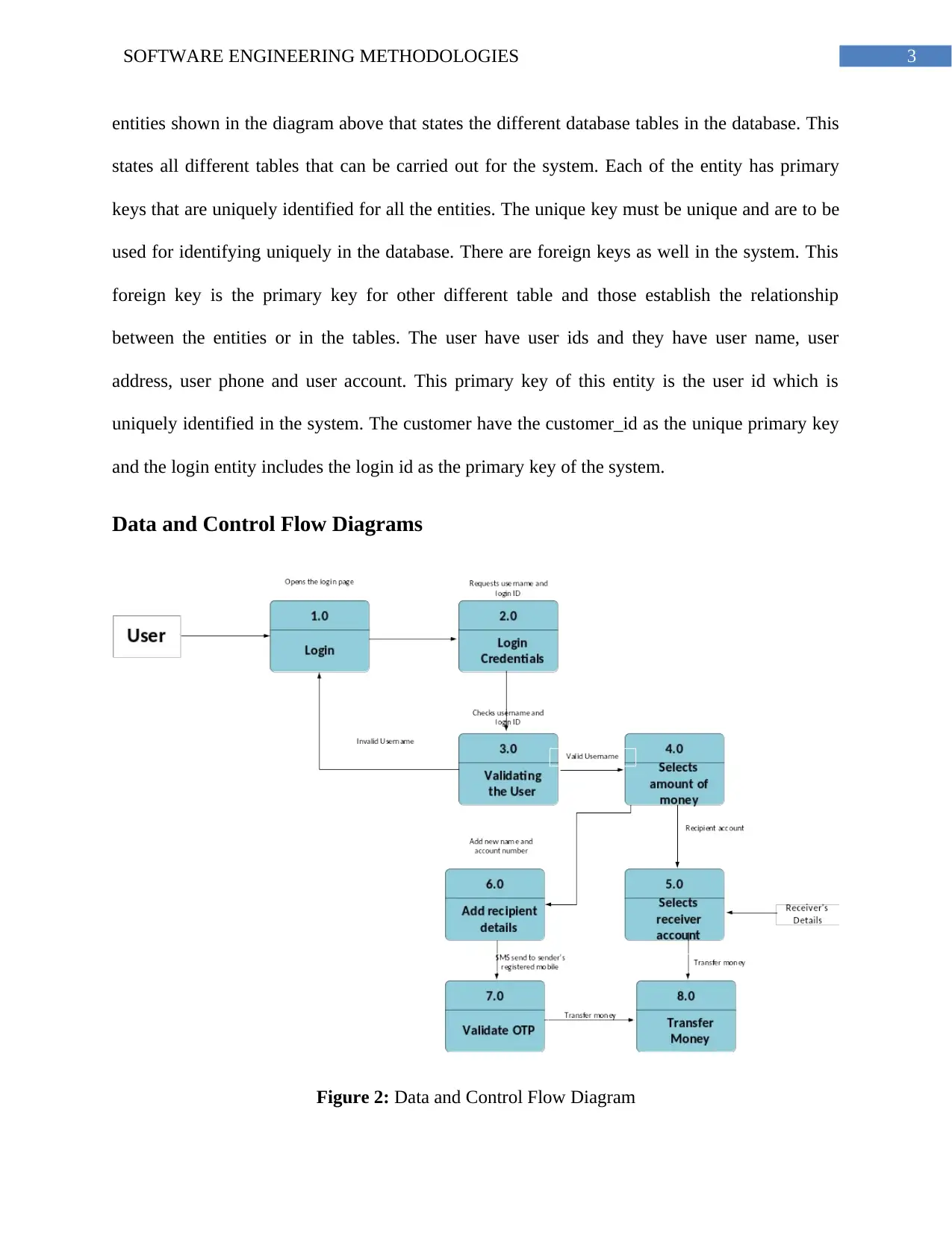
Figure 2: Data and Control Flow Diagram
Paraphrase This Document
Need a fresh take? Get an instant paraphrase of this document with our AI Paraphraser
4SOFTWARE ENGINEERING METHODOLOGIES
(Source: Created by author on Visio)
Discussion on DFDs
The above diagram shows the data flow diagram for the process of RTM system that are
carried out for most of the banks. The data flow diagrams states the different processes that are to
be taken place in the system. The system will need to perform many processes that are to be
ensured in the system. This system will defined the validation process, the control of data from
one system to another and all such processes that are valid for carrying out the system of RTM in
different banks by their customers.
The user needs to provide the OTP that states the user is valid for the money transfer.
Valid SMS should be provided for the system so that the customer can be identified uniquely. If
the SMS code is not provided by the user, the customer details will not be added in the system
and the user will not be able to send the money to the receiver.
Control Specifications
Process activation table
Money transfer Data validation SMS validation
Amount of money 1 0 0
Login for the system 0 1 0
Send money 0 0 1
Enter customer
details
0 1 0
5SOFTWARE ENGINEERING METHODOLOGIES
State machine Diagram
Figure 3: State Machine Diagram
(Source: Created by author on Visio)
Discussion on Cspec
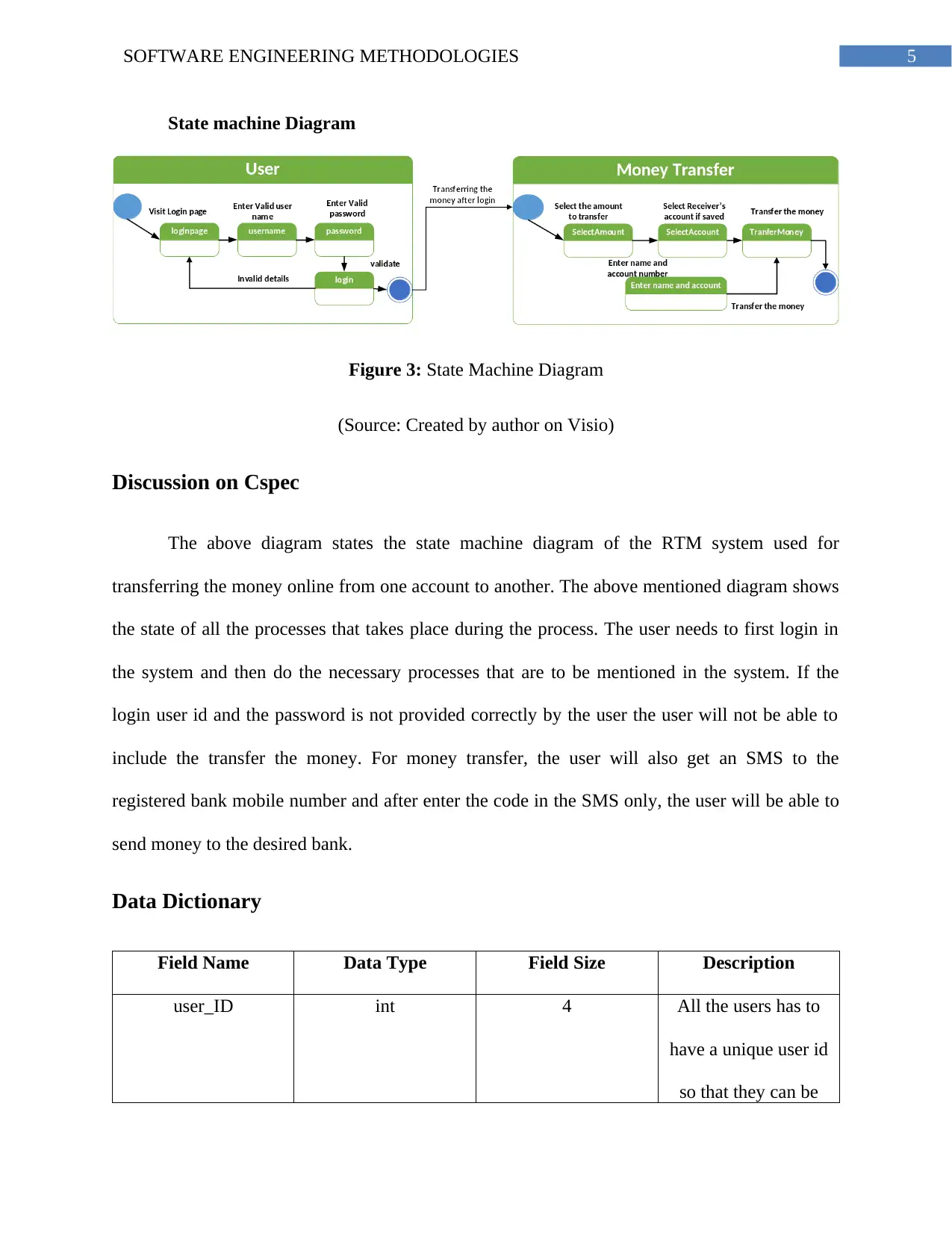
The above diagram states the state machine diagram of the RTM system used for
transferring the money online from one account to another. The above mentioned diagram shows
the state of all the processes that takes place during the process. The user needs to first login in
the system and then do the necessary processes that are to be mentioned in the system. If the
login user id and the password is not provided correctly by the user the user will not be able to
include the transfer the money. For money transfer, the user will also get an SMS to the
registered bank mobile number and after enter the code in the SMS only, the user will be able to
send money to the desired bank.
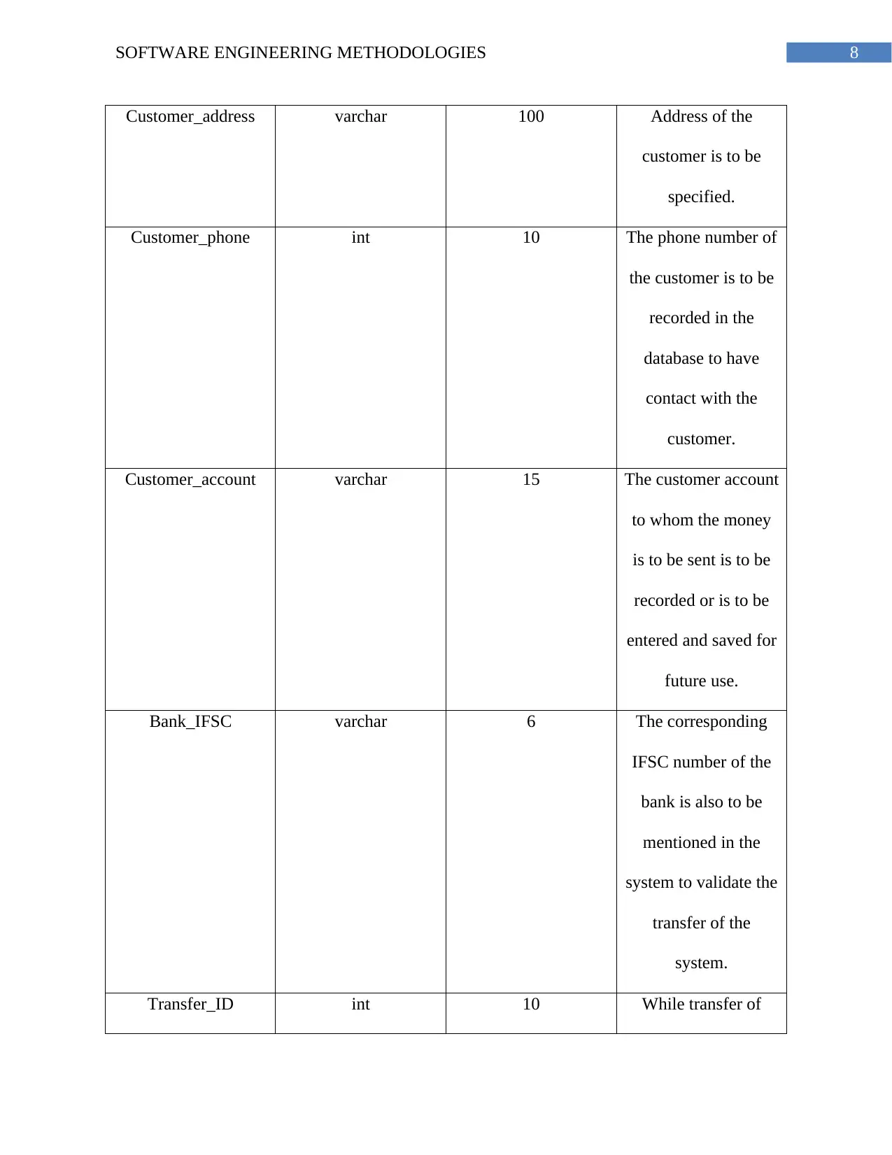
Data Dictionary
Field Name Data Type Field Size Description
user_ID int 4 All the users has to
have a unique user id
so that they can be
⊘ This is a preview!⊘
Do you want full access?
Subscribe today to unlock all pages.

Trusted by 1+ million students worldwide
6SOFTWARE ENGINEERING METHODOLOGIES
identified uniquely.
The user id are
unique for all the user
for the RMT system.
user_name varchar 50 The user name is to
be mentioned in the
database of the
system so that they
can be identified.
user_address varchar 100 The user address is
needed to the
recorded in the
database of the
system so that they
can be used for future
user.
user_phone int 10 The user phone
number should be 10
digits and the phone
numbers are
necessary for the
details as because
there is a phone
Paraphrase This Document
Need a fresh take? Get an instant paraphrase of this document with our AI Paraphraser
7SOFTWARE ENGINEERING METHODOLOGIES
number validation for
the system to transfer
money.
user_account int 15 There can be more
than one account of
the user and that
account has to be
connected with the
system so that the
user is able to send
money from all the
bank accounts.
Customer_ID int 4 There should be
customer id for all the
saved customer
details. Customer id
is the primary key
which is unique
Customer_name varchar 50 The customer name is
to be mentioned in
the system so that to
identify different
customer separately.
8SOFTWARE ENGINEERING METHODOLOGIES
Customer_address varchar 100 Address of the
customer is to be
specified.
Customer_phone int 10 The phone number of
the customer is to be
recorded in the
database to have
contact with the
customer.
Customer_account varchar 15 The customer account
to whom the money
is to be sent is to be
recorded or is to be
entered and saved for
future use.
Bank_IFSC varchar 6 The corresponding
IFSC number of the
bank is also to be
mentioned in the
system to validate the
transfer of the
system.
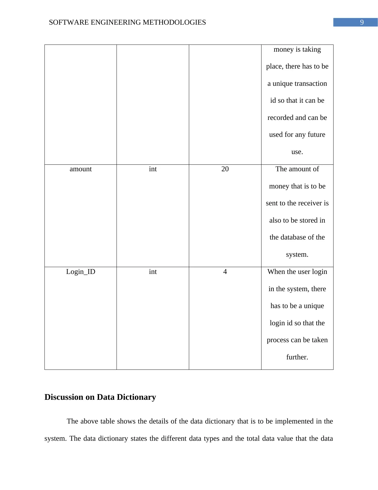
Transfer_ID int 10 While transfer of
⊘ This is a preview!⊘
Do you want full access?
Subscribe today to unlock all pages.

Trusted by 1+ million students worldwide
9SOFTWARE ENGINEERING METHODOLOGIES
money is taking
place, there has to be
a unique transaction
id so that it can be
recorded and can be
used for any future
use.
amount int 20 The amount of
money that is to be
sent to the receiver is
also to be stored in
the database of the
system.
Login_ID int 4 When the user login
in the system, there
has to be a unique
login id so that the
process can be taken
further.
Discussion on Data Dictionary
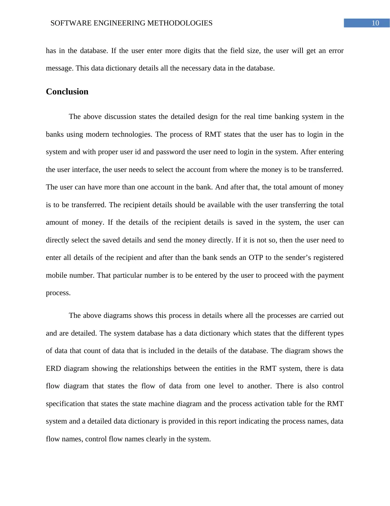
The above table shows the details of the data dictionary that is to be implemented in the
system. The data dictionary states the different data types and the total data value that the data
Paraphrase This Document
Need a fresh take? Get an instant paraphrase of this document with our AI Paraphraser
10SOFTWARE ENGINEERING METHODOLOGIES
has in the database. If the user enter more digits that the field size, the user will get an error
message. This data dictionary details all the necessary data in the database.
Conclusion
The above discussion states the detailed design for the real time banking system in the
banks using modern technologies. The process of RMT states that the user has to login in the
system and with proper user id and password the user need to login in the system. After entering
the user interface, the user needs to select the account from where the money is to be transferred.
The user can have more than one account in the bank. And after that, the total amount of money
is to be transferred. The recipient details should be available with the user transferring the total
amount of money. If the details of the recipient details is saved in the system, the user can
directly select the saved details and send the money directly. If it is not so, then the user need to
enter all details of the recipient and after than the bank sends an OTP to the sender’s registered
mobile number. That particular number is to be entered by the user to proceed with the payment
process.
The above diagrams shows this process in details where all the processes are carried out
and are detailed. The system database has a data dictionary which states that the different types
of data that count of data that is included in the details of the database. The diagram shows the
ERD diagram showing the relationships between the entities in the RMT system, there is data
flow diagram that states the flow of data from one level to another. There is also control
specification that states the state machine diagram and the process activation table for the RMT
system and a detailed data dictionary is provided in this report indicating the process names, data
flow names, control flow names clearly in the system.

11SOFTWARE ENGINEERING METHODOLOGIES
⊘ This is a preview!⊘
Do you want full access?
Subscribe today to unlock all pages.

Trusted by 1+ million students worldwide
1 out of 13
Related Documents
Your All-in-One AI-Powered Toolkit for Academic Success.
+13062052269
info@desklib.com
Available 24*7 on WhatsApp / Email
![[object Object]](/_next/static/media/star-bottom.7253800d.svg)
Unlock your academic potential
Copyright © 2020–2026 A2Z Services. All Rights Reserved. Developed and managed by ZUCOL.


