ITECH7410 Software Engineering Methodologies: RMT System Analysis
VerifiedAdded on 2022/12/27
|11
|1083
|24
Report
AI Summary
This report provides a comprehensive analysis of a real-time money transfer (RMT) system, commonly used in Australia. The analysis includes the creation and discussion of various diagrams, such as Entity-Relationship Diagrams (ERD), Data Flow Diagrams (DFD), Control Flow Diagrams (CFD), and state machine diagrams with process activation tables. These diagrams illustrate the flow of data and control within the system, from customer login to transaction completion. Furthermore, the report includes a detailed data dictionary, outlining the data types, ranges, and constraints for the system's database. The report concludes with an assessment of the system's processes, highlighting the optionality in beneficiary selection and the successful representation of these processes through the diagrams.

Running head: SOFTWARE ENGINEERING
Real time money transfer system
Name of the Student
Name of the University
Author Note
Real time money transfer system
Name of the Student
Name of the University
Author Note
Paraphrase This Document
Need a fresh take? Get an instant paraphrase of this document with our AI Paraphraser
1
SOFTWARE ENGINEERING
Table of Contents
Introduction................................................................................................................................2
Diagrams....................................................................................................................................2
ERD........................................................................................................................................2
DFD........................................................................................................................................2
CFD........................................................................................................................................2
CSpec.....................................................................................................................................2
Data Dictionary......................................................................................................................2
Conclusion..................................................................................................................................2
2
SOFTWARE ENGINEERING
Introduction
Real-time systems are most widely used for the transaction based systems. Real- time
means that the operation and processes in the system has a well-defined fixed time. The
system design requires the real time computing capacity and the outputs are consistently
getting stored in the database (Rolph, Stein & Stunder, 2017). In this report, a real-time
system named RMT (Real-time Money Transfer) which is widely used software/app in
Australia, is analysed. The transaction between two accounts via this system and its flow is
also observed by developing Entity-Relationship models, data flow diagram, control flow
diagram and a state machine diagram with process activation table. The diagrams are also
discussed in terms of a real time system.
Diagrams
ERD
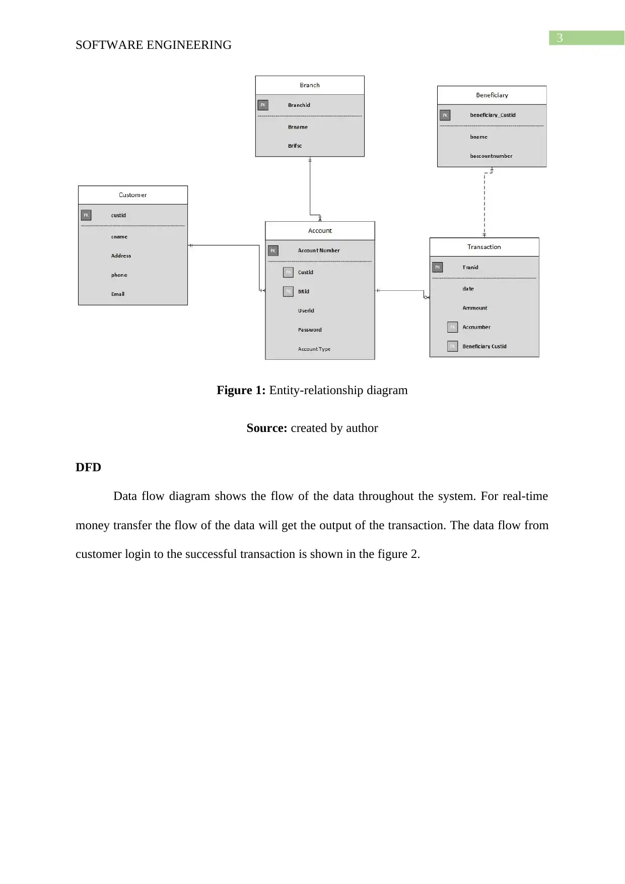
The real time money transfer will require customer’s data and the transaction to be
fetched and stored in parallel and simultaneously. As it has a login feature the login data is
needed to be store in the database. Figure 1 shows the conceptual schema of the database.
⊘ This is a preview!⊘
Do you want full access?
Subscribe today to unlock all pages.

Trusted by 1+ million students worldwide
3
SOFTWARE ENGINEERING
Figure 1: Entity-relationship diagram
Source: created by author
DFD
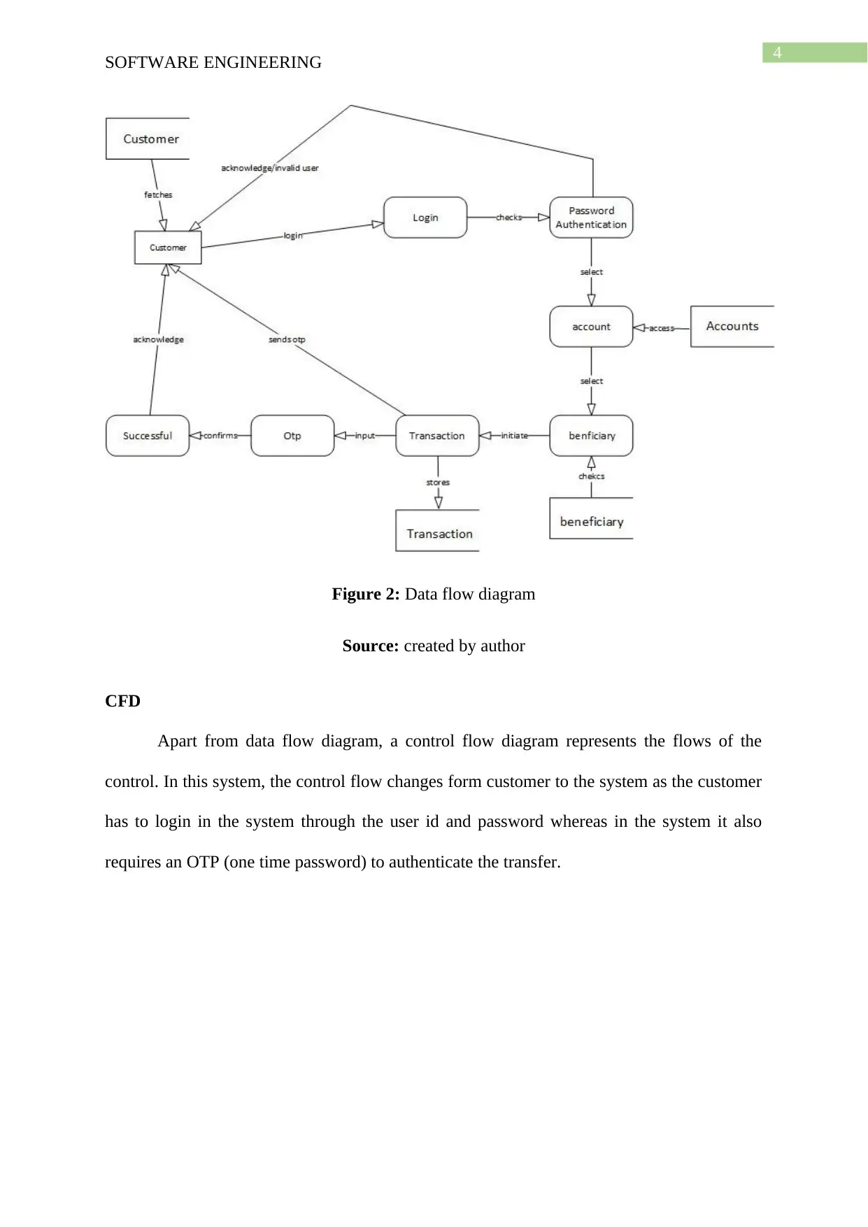
Data flow diagram shows the flow of the data throughout the system. For real-time
money transfer the flow of the data will get the output of the transaction. The data flow from
customer login to the successful transaction is shown in the figure 2.
Paraphrase This Document
Need a fresh take? Get an instant paraphrase of this document with our AI Paraphraser
4
SOFTWARE ENGINEERING
Figure 2: Data flow diagram
Source: created by author
CFD
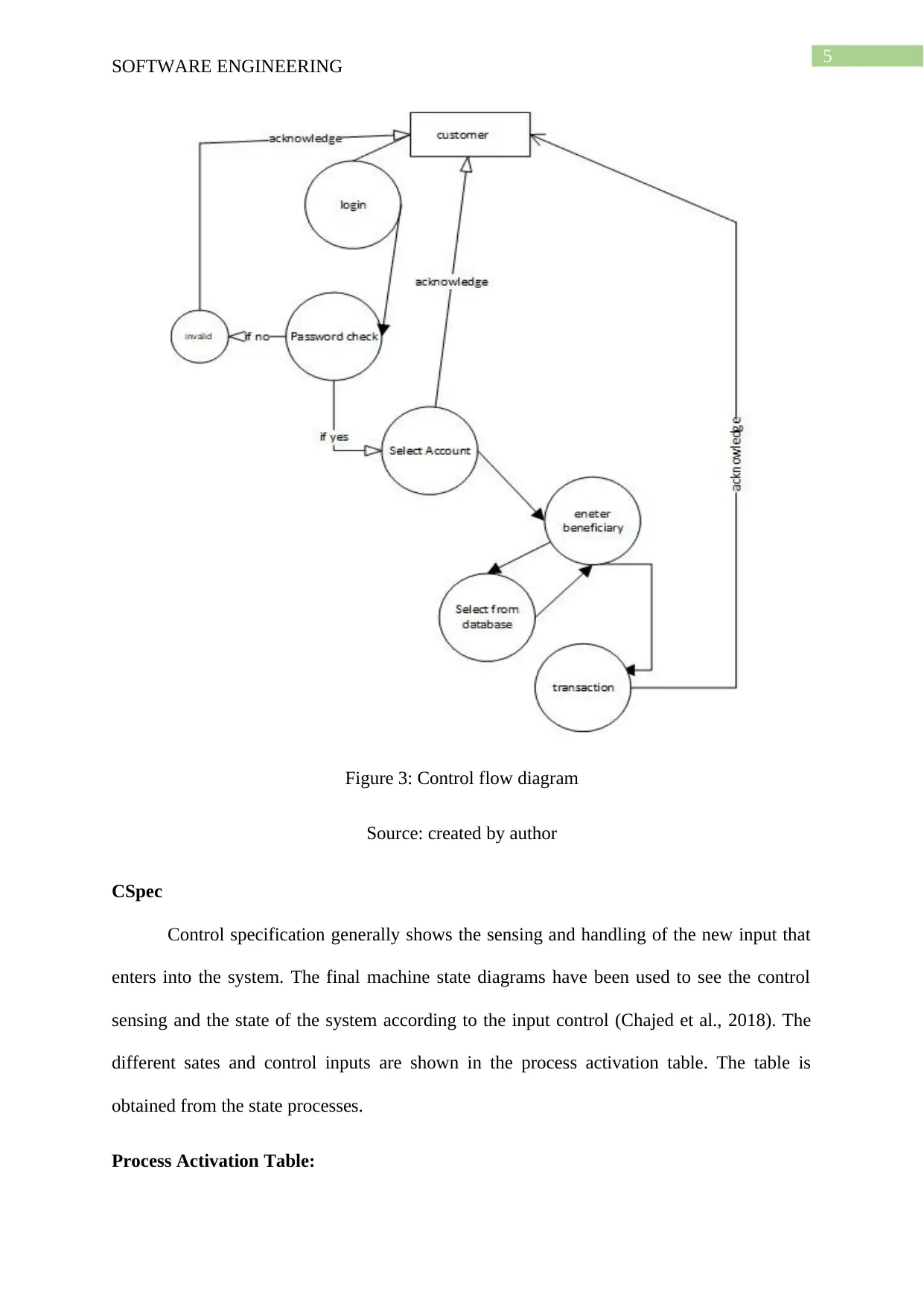
Apart from data flow diagram, a control flow diagram represents the flows of the
control. In this system, the control flow changes form customer to the system as the customer
has to login in the system through the user id and password whereas in the system it also
requires an OTP (one time password) to authenticate the transfer.
5
SOFTWARE ENGINEERING
Figure 3: Control flow diagram
Source: created by author
CSpec
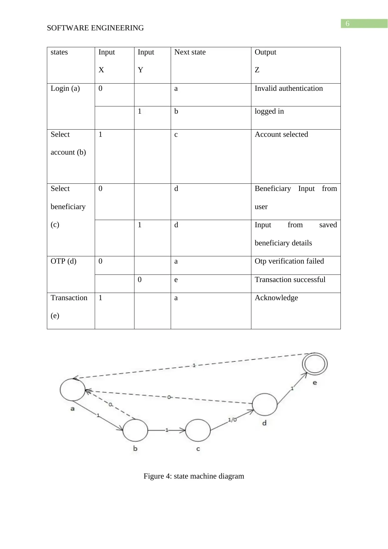
Control specification generally shows the sensing and handling of the new input that
enters into the system. The final machine state diagrams have been used to see the control
sensing and the state of the system according to the input control (Chajed et al., 2018). The
different sates and control inputs are shown in the process activation table. The table is
obtained from the state processes.
Process Activation Table:
⊘ This is a preview!⊘
Do you want full access?
Subscribe today to unlock all pages.

Trusted by 1+ million students worldwide
6
SOFTWARE ENGINEERING
states Input
X
Input
Y
Next state Output
Z
Login (a) 0 a Invalid authentication
1 b logged in
Select
account (b)
1 c Account selected
Select
beneficiary
(c)
0 d Beneficiary Input from
user
1 d Input from saved
beneficiary details
OTP (d) 0 a Otp verification failed
0 e Transaction successful
Transaction
(e)
1 a Acknowledge
Figure 4: state machine diagram
Paraphrase This Document
Need a fresh take? Get an instant paraphrase of this document with our AI Paraphraser
7
SOFTWARE ENGINEERING
Source: created by author
Data Dictionary
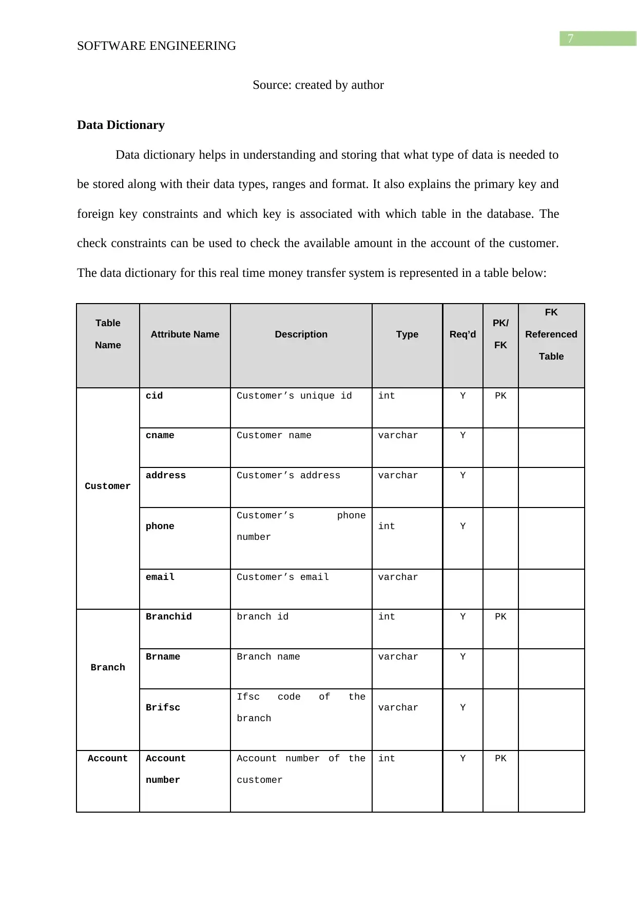
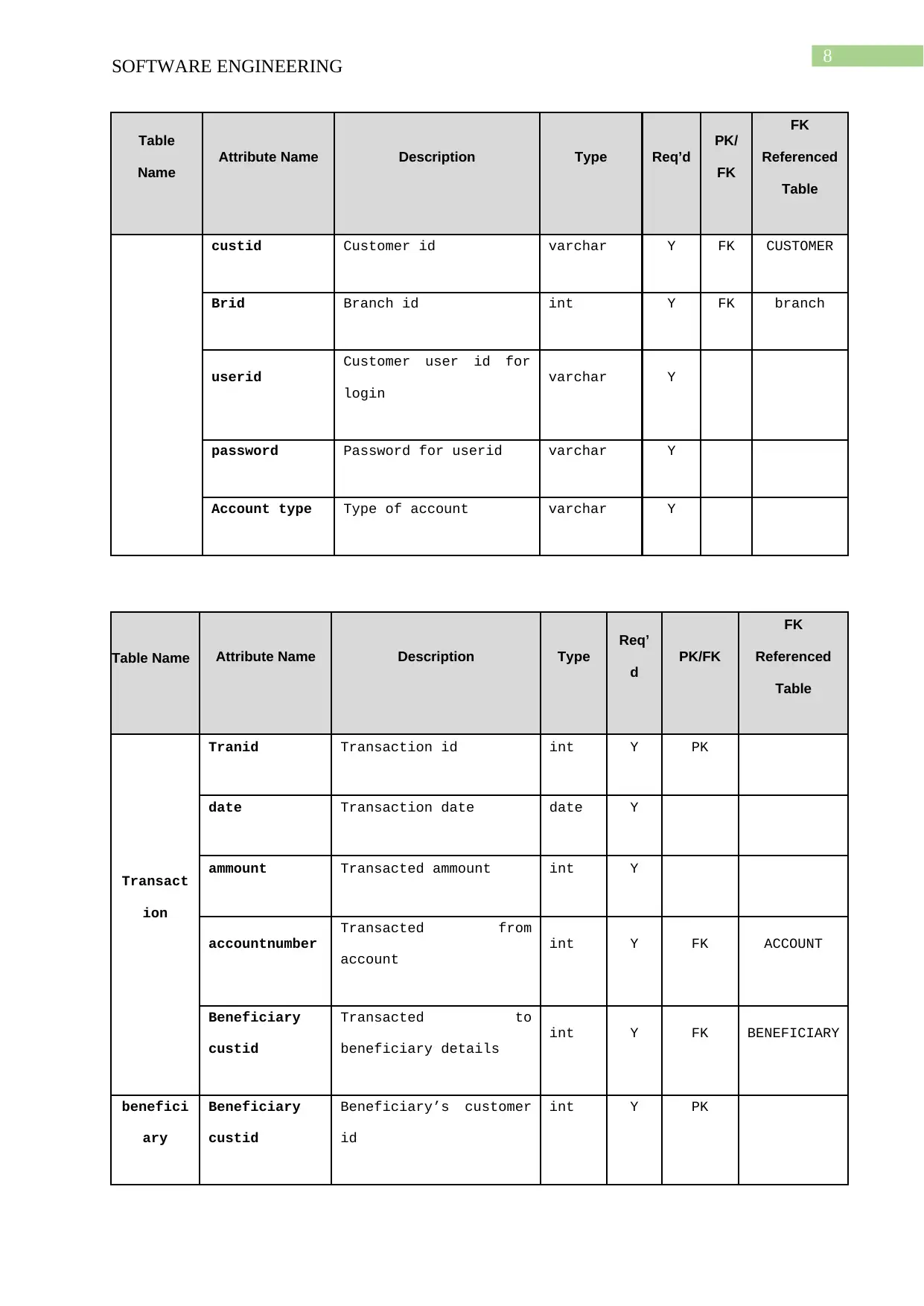
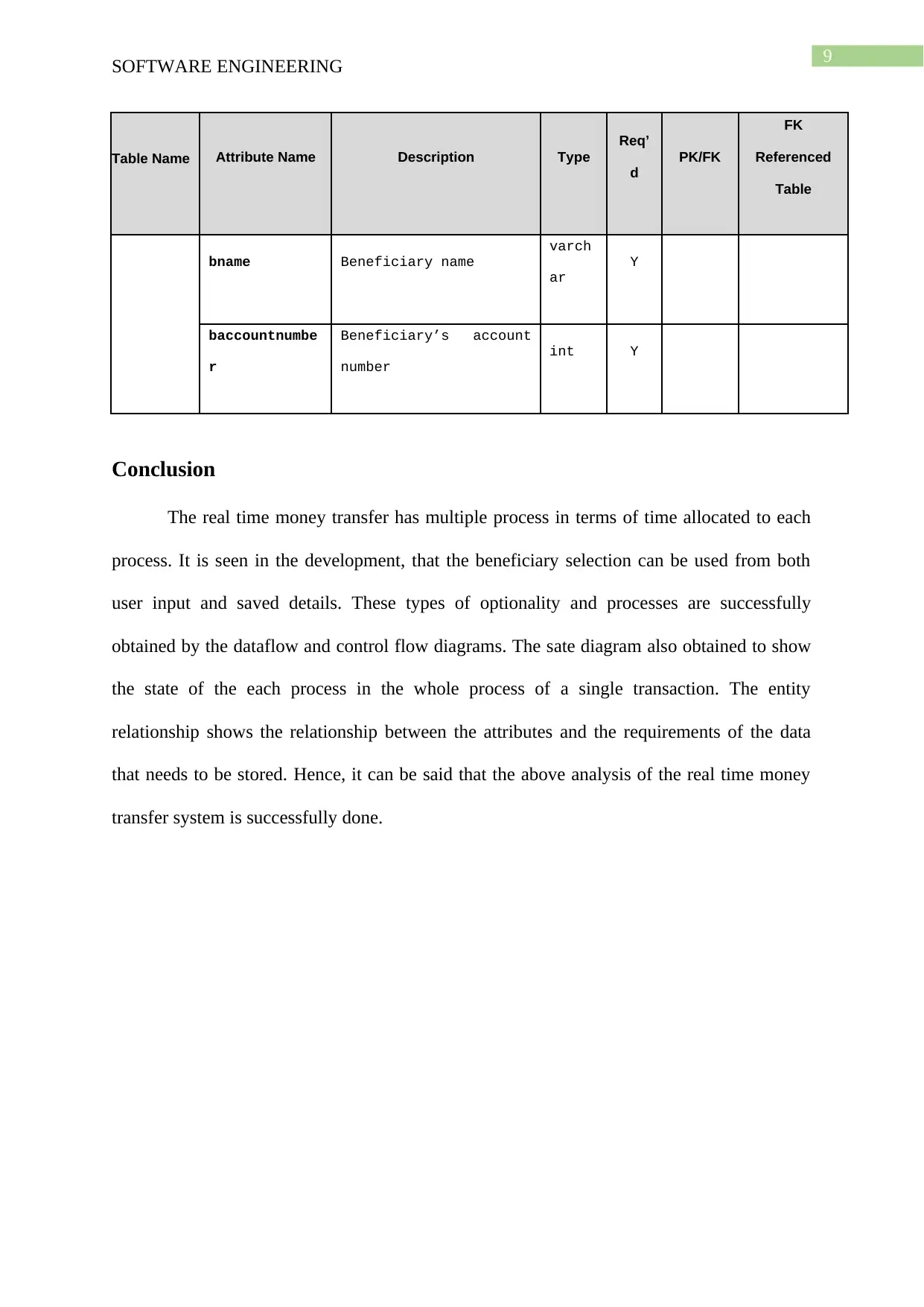
Data dictionary helps in understanding and storing that what type of data is needed to
be stored along with their data types, ranges and format. It also explains the primary key and
foreign key constraints and which key is associated with which table in the database. The
check constraints can be used to check the available amount in the account of the customer.
The data dictionary for this real time money transfer system is represented in a table below:
Table
Name
Attribute Name Description Type Req’d
PK/
FK
FK
Referenced
Table
Customer
cid Customer’s unique id int Y PK
cname Customer name varchar Y
address Customer’s address varchar Y
phone
Customer’s phone
number
int Y
email Customer’s email varchar
Branch
Branchid branch id int Y PK
Brname Branch name varchar Y
Brifsc
Ifsc code of the
branch
varchar Y
Account Account
number
Account number of the
customer
int Y PK
8
SOFTWARE ENGINEERING
Table
Name
Attribute Name Description Type Req’d
PK/
FK
FK
Referenced
Table
custid Customer id varchar Y FK CUSTOMER
Brid Branch id int Y FK branch
userid
Customer user id for
login
varchar Y
password Password for userid varchar Y
Account type Type of account varchar Y
Table Name Attribute Name Description Type
Req’
d
PK/FK
FK
Referenced
Table
Transact
ion
Tranid Transaction id int Y PK
date Transaction date date Y
ammount Transacted ammount int Y
accountnumber
Transacted from
account
int Y FK ACCOUNT
Beneficiary
custid
Transacted to
beneficiary details
int Y FK BENEFICIARY
benefici
ary
Beneficiary
custid
Beneficiary’s customer
id
int Y PK
⊘ This is a preview!⊘
Do you want full access?
Subscribe today to unlock all pages.

Trusted by 1+ million students worldwide
9
SOFTWARE ENGINEERING
Table Name Attribute Name Description Type
Req’
d
PK/FK
FK
Referenced
Table
bname Beneficiary name
varch
ar
Y
baccountnumbe
r
Beneficiary’s account
number
int Y
Conclusion
The real time money transfer has multiple process in terms of time allocated to each
process. It is seen in the development, that the beneficiary selection can be used from both
user input and saved details. These types of optionality and processes are successfully
obtained by the dataflow and control flow diagrams. The sate diagram also obtained to show
the state of the each process in the whole process of a single transaction. The entity
relationship shows the relationship between the attributes and the requirements of the data
that needs to be stored. Hence, it can be said that the above analysis of the real time money
transfer system is successfully done.
Paraphrase This Document
Need a fresh take? Get an instant paraphrase of this document with our AI Paraphraser

10
SOFTWARE ENGINEERING
Reference
Chajed, T., Kaashoek, F., Lampson, B., & Zeldovich, N. (2018). Verifying concurrent software using
movers in {CSPEC}. In 13th {USENIX} Symposium on Operating Systems Design and
Implementation ({OSDI} 18) (pp. 306-322).
Rolph, G., Stein, A., & Stunder, B. (2017). Real-time environmental applications and display sYstem:
READY. Environmental Modelling & Software, 95, 210-228.
1 out of 11
Related Documents
Your All-in-One AI-Powered Toolkit for Academic Success.
+13062052269
info@desklib.com
Available 24*7 on WhatsApp / Email
![[object Object]](/_next/static/media/star-bottom.7253800d.svg)
Unlock your academic potential
Copyright © 2020–2026 A2Z Services. All Rights Reserved. Developed and managed by ZUCOL.


