Energy and Environmental Studies
VerifiedAdded on 2020/10/05
|38
|7481
|115
AI Summary
The provided document is an assignment on energy and environmental studies, covering topics such as power plant design, renewable energy resources, and environmental impact. The assignment includes case studies from Oman's Suhar Aluminium Power Plant and discusses the need for sustainable energy solutions, highlighting the importance of eco-friendly practices in the energy sector.
Contribute Materials
Your contribution can guide someone’s learning journey. Share your
documents today.

Project
Secure Best Marks with AI Grader
Need help grading? Try our AI Grader for instant feedback on your assignments.
Abstract
Sohar Aluminium Power plant is located at Sohar port in Oman but as per the economical and
environmental situations of the plants, it is losing its efficiency. This Power Plant is mainly
designed to supply 1000 MW per hour which can be operated by the gas turbines. Oman gas
Company uses Fuel and Oil as the main source of electricity generator where natural and local
gas station is used to supply HP and LP temperature to power plant. Gas turbine was mainly
placed to control the temperature and avoid the disturbance in burning gas.
This system is also used to consume the same gas that helped in functioning of the water
bath heater. However, heater consists of the burner that gets damaged with the changing
temperature of the humidity outside it. In order to get bath heater properly functioned, some
maintenance are provided to start it again. New project is developed to avoid such issues and can
be replaced with lP steam using same burner and also the cost is also minimum as compared to
the ready-made system after modification. Various advantages are included in this project as
compared to the older ones such as improved efficiency. Less maintenance, minimum cost, Low
steam cost etc.

ACKNOWLEDGEMENT
We would like to express our gratitude towards all the team who is involved in making
the project a successfully. Accomplishment of this project could be little difficult without the
cooperation and contribution of this hard working team. Also, we would also like to thanks our
superior subordinate who has helped throughout the complete process and make it achieving it as
a successful accomplishment of the project. We are also great full to all the members and
employees who helped in providing the valuable thoughts and ideas in improving the operational
efficiency and finally all the people who have helped in finalising the plant.
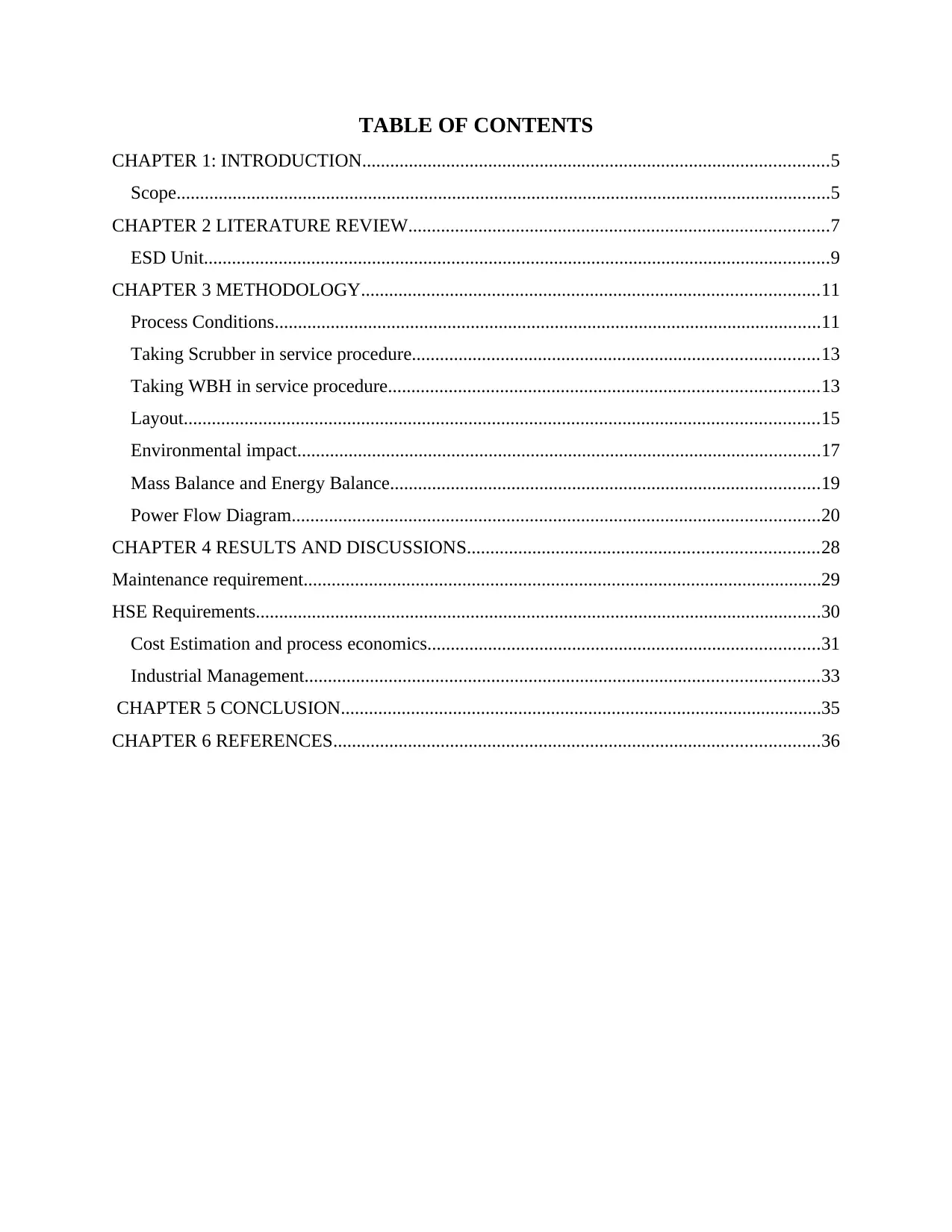
TABLE OF CONTENTS
CHAPTER 1: INTRODUCTION....................................................................................................5
Scope............................................................................................................................................5
CHAPTER 2 LITERATURE REVIEW..........................................................................................7
ESD Unit......................................................................................................................................9
CHAPTER 3 METHODOLOGY..................................................................................................11
Process Conditions.....................................................................................................................11
Taking Scrubber in service procedure.......................................................................................13
Taking WBH in service procedure............................................................................................13
Layout........................................................................................................................................15
Environmental impact................................................................................................................17
Mass Balance and Energy Balance............................................................................................19
Power Flow Diagram.................................................................................................................20
CHAPTER 4 RESULTS AND DISCUSSIONS...........................................................................28
Maintenance requirement...............................................................................................................29
HSE Requirements.........................................................................................................................30
Cost Estimation and process economics....................................................................................31
Industrial Management..............................................................................................................33
CHAPTER 5 CONCLUSION.......................................................................................................35
CHAPTER 6 REFERENCES........................................................................................................36
Secure Best Marks with AI Grader
Need help grading? Try our AI Grader for instant feedback on your assignments.
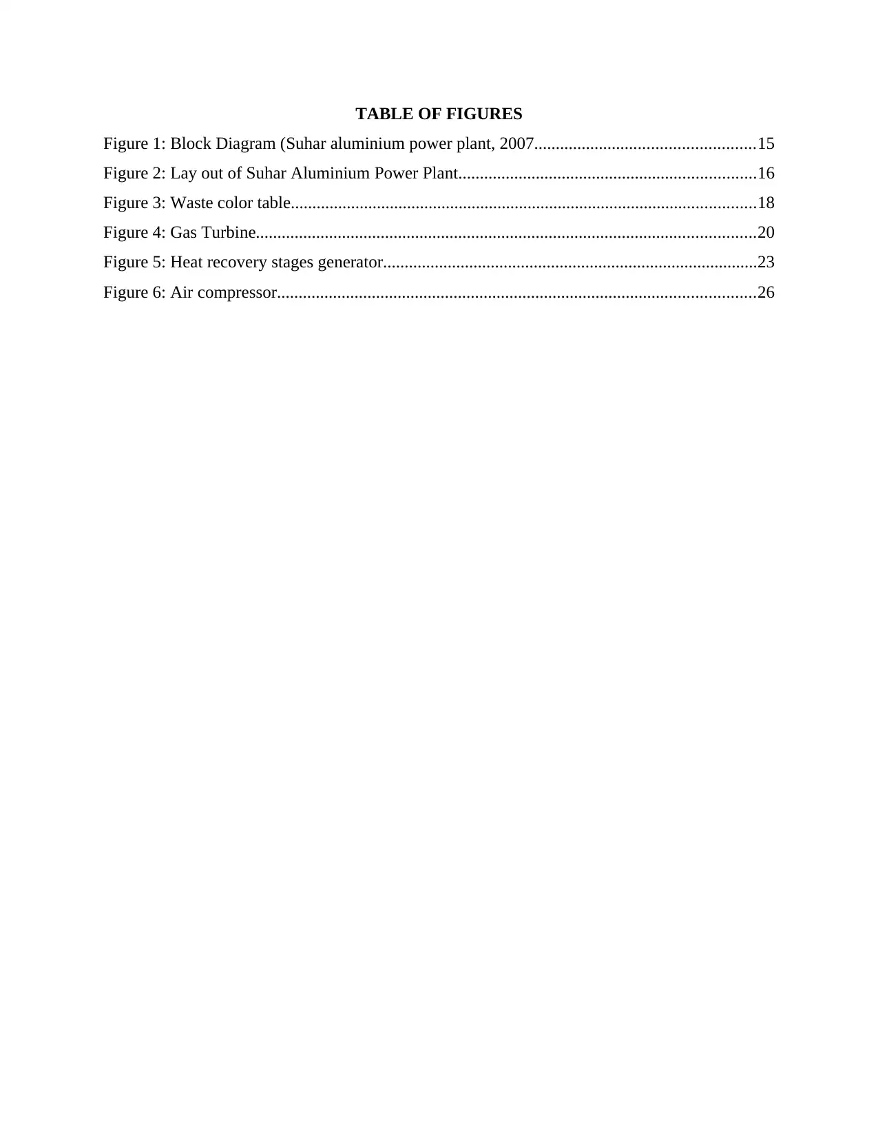
TABLE OF FIGURES
Figure 1: Block Diagram (Suhar aluminium power plant, 2007...................................................15
Figure 2: Lay out of Suhar Aluminium Power Plant.....................................................................16
Figure 3: Waste color table............................................................................................................18
Figure 4: Gas Turbine....................................................................................................................20
Figure 5: Heat recovery stages generator.......................................................................................23
Figure 6: Air compressor...............................................................................................................26
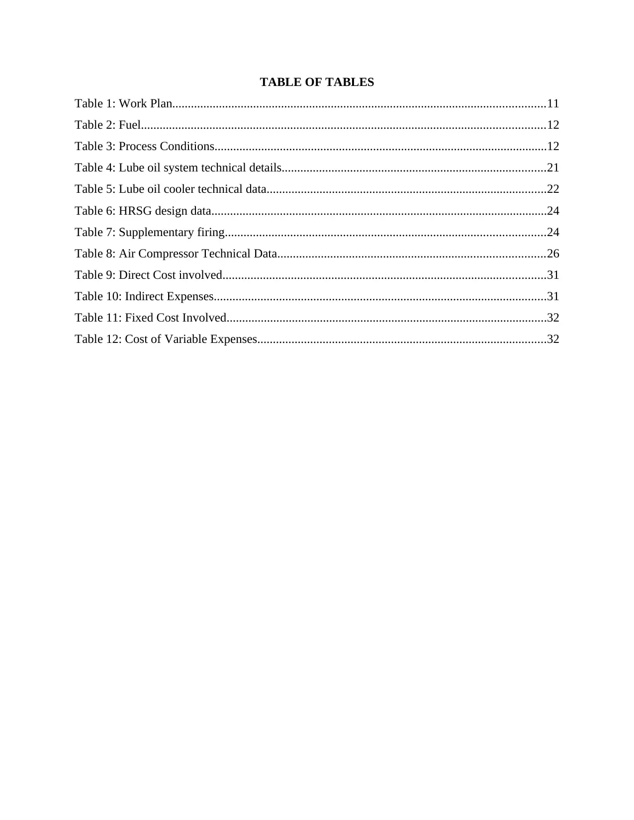
TABLE OF TABLES
Table 1: Work Plan........................................................................................................................11
Table 2: Fuel..................................................................................................................................12
Table 3: Process Conditions...........................................................................................................12
Table 4: Lube oil system technical details.....................................................................................21
Table 5: Lube oil cooler technical data..........................................................................................22
Table 6: HRSG design data............................................................................................................24
Table 7: Supplementary firing.......................................................................................................24
Table 8: Air Compressor Technical Data......................................................................................26
Table 9: Direct Cost involved........................................................................................................31
Table 10: Indirect Expenses...........................................................................................................31
Table 11: Fixed Cost Involved.......................................................................................................32
Table 12: Cost of Variable Expenses.............................................................................................32
CHAPTER 1: INTRODUCTION
King of the Oman has been given a power of the combined cycle power plant which uses
both gas and steam turbine and has a installing capacity of 24 million units per day. Turbine
ensures the flow of gas and steam generators are used for recovery of heat. This power plant was
specially designed in order to supply the aluminium smelter which was one of the quality based
smelter in Oman (Abdalla And et.al, 2016). Proper operations of the boiler is controlled by
burner management system. Evaporative coolers system was there to control the temperature and
increase the output. Desalination plant supplies osmosis which further supply de-mineralized
plant.
Functioning of this plant can be possible by either natural gas or fuel oil which is handled
by automatic controller in case of any emergency. Water supply was agreed upon 10 degree
Celsius with ministry of environment. Various components are involved in fuel gas supply
system such as metering station, liquid separator, recovery condensate tank etc. The Dew point is
used to control the temperature of inlet and outlet gas. Local control panel and water bath
temperature are also used to downstream the gas temperature. As water bath heater fails in high
humidity so heater system is being added from HRSG system in order to heat the gas. So
changes are being made in this Sohar Aluminium power plant because trips and manpower is
very costly in Oman.
Problem
The problem with the bathing heater is that it does not function efficiently due to
excessive flow of the gas inside the chamber and this effects the filter. Because of the low
temperature of the gas, it causes malfunction to filter
Objectives
Increased efficiency of natural gas.
Minimum maintenance cost.
low cost of steam.
Scope
Various areas are included to increase the temperature of the gas. Project area for power plant: This can be referred as the area required for the project that
is 20 by 20 m. so it needs to be located at the area which is far away from residential
Paraphrase This Document
Need a fresh take? Get an instant paraphrase of this document with our AI Paraphraser
places. For selecting the area for power plant, it needs to be build at such places from
which roads and highways can be easily accessible. In order to avoid disturbance of
machinery good spaces are allotted to such projects. Manpower availability: In order to get the effective and efficient results of the project,
skilled manpower is needed to be encouraged. Disposal of waste water: As projects power plant project includes large amount of waste
so it need to be efficiently disposed in a pit. In order to reduce the cost of transfer facility,
close disposable pit need to be considered. Availability of power supply: This is one of the important criteria which need to be
selected wisely in order to minimise the cost of power consumption. HRSG and place near gas turbines: This selection criteria helps in reducing the piping
and structure of the project that ultimately helps in lower cost of the project. Complex
Design of the project may be responsible for low quality production. Fire extinguished area: As the main operations of the power plant deals with two
flammable substances such as oil gas and fuel. So the area need to be protected with fire
extinguisher in case of any uncertainty. Ground surface level: Uneven surface may be responsible for weak points in ground so
this need to be considered while selecting the criteria for project that surface shoul be flat. Avoiding future expansion: if future expansion of the project will be considered so the
the project will be developed keeping a future perspectives in mind. Therefore future
expansions are initially avoided in order to avoid the disturbance of pipe crossing and
complex structure. Various things need to be restricted such as power supply, safety
rules, supplier capacity, area, non sparky equipments and restricted cell phones within the
specific area.
Clear positioning of Entry and exit: This is the one of the important perspective which
need to be considered as this project basically deals with flammable substances that are
dangerous in nature. In case of any emergency safety measures need to be prioritize.
CHAPTER 2 LITERATURE REVIEW
The power plant is commonly used to generate the electricity and distribution of the
power supply in a locality. The Sohar aluminium smelter gets the supply of power supply in
order to produce aluminium. Aluminium smelter are generally consuming the power of 650 MW
(Abdalla And et.al., 2015). It also supplies various auxiliaries that consumes more electricity.
This contains two smelters line-01 and line-02 namely OETC.01 and OETC.02 which are 220
KV in power that is further connected with Gas insulation station. The Four turbine of the power
plant having a capacity of 170MW in gas turbine and 218 MW in steam turbine will be operated
by natural gas or fuel. Among which two are connected with low pressure boilers and two are
connected with low pressure steam.
A gas turbine model is very efficient having a capacity of 13E2 GE, consists of 21 stages
and 72 EV burner. Compressor generally contains five stages which helps in compressing the air
at the scale of 1 to 16 bar Evaporator cooler in combustor increases the efficiency up-to 18MW
at the time of summer. The gas turbine includes the cycle of operation in order to generate the
electricity. This operation cycle includes intake air which is compressed from 1st to 16th bar that
results in production of heat and rotation of shaft at a speed of 3000rpm and cuts the magnetic
field to generate electricity.
The HRGS (Heat recovery Steam Generation) generally consists of four different stages ,
includes Super Heater, Evaporator, Economizer etc. It generates low pressure and high pressure
steam. The HRGS exhaust the heat supplied from the gas turbines and each boiler is provided
with gas firing system that is located at the side of super heater that produces high pressure.
However low pressure super heated steam is provided with low pressure steam. it is used
to control high pressure of the water and low pressure of pump which is directed towards low
pressure economizer and collected in a low pressure drum. Control value collects the pressure
drum before it reaches to other stage of boiler.
Feed water pump controls high and low pressure of the water pump which passes directly to high
pressure economizer. Then it enters into high pressure drum which is generally controlled by
control value. HRSG includes de-super heated for controlling the temperature of the steam. Then
high pressure spray water will be supplied by high pressure spray water that passes to
economiser stage. Temperature and pressure of every stage will be different accordingly.
Water bath heater
Water bath Heater are provisioned to heat the gas to control the minimum inlet
temperature which will be 13 degree Celsius. It also controls the maximum gas flow as 26.1kg/s
and pressure as 35 brag. The heaters are generally provided in order to configured to control the
streams for GT blocks 1 and 2. The temperature signal helps in resetting the point of bath
temperature which is generally used in controlling bath temperature. This bath temperature is
aimed at restricting the maximum value in DCS whose value needs to be 85 degree Celsius. In
order to prevent the overpressure of the tube, tube side relief is provided that helps in controlling
the high pressure of the heated coil (Al Rahbi and et.al., 2017). In case of gas expansion, if the
bath heater being blocked and the temperature rises above then this tube value helps in
controlling the temperature of the power plant. Over heating of the bath heater is protected in
case of water loss in order to prevent fire tube from excessive heating. Local burner
management helps in applying secuence logic to panel and also helps the shut down of the
burner (The engineering toolbox, Basic Information for Engineering and Design of Technical
Applications ,2010). This logic is mainly aimed at preventing fire tube from explosion. Also low
fuel gas supply pressure will be controlled by pressure switch. Low water level in bath heater
will be controlled by level switch. Main burner and pilot burner will helps in the extinguishing
the whole heater bath in case if any of the above units will not be able to control the temperature
of heater. This restricts the flow of fuel gas supply and thus avoids the fire explosion.
In addition to it, a local panel is also available that provides the indication of the heater
weather it is on or off. This will be controlled remotely as DCS and BMS panel allows the flow
of operations. It also helps in regulating the flow of fuel which needs to be stated at 1.4 brag. In
order to monitor the functioning of the heater and to control the upstream and down stream
pressure, local pressure gauges are generally used. Also heater contains one of the flammable
substance for the functioning of the system so A local flow meter is available that basically
monitors the consumption of fuel gas. There is also a ionised flame detector is present which
detects the spark and flames, if generated outside the heater. A suitable corrosion will have to be
mixed in order to serve the required water. Gas detector should be placed near the burner so that
propagated flame will be automatically detected with the help of mesh type flare arrestor. Gas
detector will also helps in detecting the gas leakage of the heater to avoid any uncertain
explosion within the bath heater.
Secure Best Marks with AI Grader
Need help grading? Try our AI Grader for instant feedback on your assignments.
However, the plant is meant for producing the electricity giving rise to gas cloud that is
generally ignited by the bath heater. In order to protect the bath heater from unwanted practices
of explosion the shell or covering of the heater will be insulated with the help of heat
conservation material such as mineral wool etc. Also the intake will be protected from inside to
reduce the noise as conversion of the heat and light energy produces sound. This mainly consists
of main regulating steam which is 4*100% insulated from the outer disturbance.
PRS Skid
every module contains the self-acting regulator that basically uses the fuel gas to process
for application of the desired force or tapping pressure. A creep value is used to control the
stream capacity which is mainly rated at 10% and stated at 27.5 brag. Pressure reducing value of
the downstream is provided in order to set no-flow condition for avoiding the excessive flow of
pressure. A mechanical slam shut off value is generally located at the upper side of the active
regulator and also controls the the limit of the pressure if it goes above or below pre stated value.
Over pressure of the downstream pressure will be prevented by this controller (Al-Wahaibi and
Zeka, 2015). The slam shut is a basically is loaded with spring in order to detect the value of the
temperature that helps in shuting off and on. Upstream and down stream of the of the regulator is
supported by the local remote pressure indication which functions automatically according to the
changes occurred in GT fuel demand. It also maintains the pressure supplied in GT fuel supply
header.
ESD Unit
It can be determined as the Gas station inlet ESD value that helps in energising the flow
of fuel that produces energy to the system. This is a solenoid value that is generally helps in
energising the DCS system which fails to produce energy. It mainly contains open and closed
switches that restricts the flow of energy from one module to another. The main closure value of
the ESD is generated from DCS with the help of the push button station. It can also be manually
reset on the ESD panel.
Inlet filter scrubber unit: This is a filter separator that provisioned the emergency devices in
order to shut off the device. This mainly helps in removing the water droplets or solid particles
which are formed at the structure of the pipeline. It also helps in removing the corrosion products
which are produced at pipeline. This scrubber mainly consists of two stages that is Vane pack
and Coalesce element. The first one is used to eliminate the liquid formed and the second stage is
aimed at Coalesce the liquid from both the side of the gauges. This produced liquid will be
automatically drained out with the help of the drain traps.
Condensate Drain system: It is mainly used to condensate the liquid produced at both the sides
of the level gauges. It acts as a condensation module that helps in collecting the liquid from the
filter separator. This tank basically contains a local vent that allows to flash the vapours collected
during the procedure. It provides the condensate pumps which are manually started with the high
level of pressure and functions automatically till it reaches to low level.
Condensate Drain vessel: This can be referred as a installation or operation which do not
contains any internals and therefore it never requires any maintenance inside it. Here the vent is
normally connected to the values that consists of nitrogen and isolate values. In order to prevent
spontaneous ignition or any pyrophoric iron, the vessel need to be completely washed with the
help of the water. Also various company standards need to be followed while condensation the
vessel completely for its smooth functioning.
Condensate pump: This pump need to be maintained for the smooth functioning of the system.
Vender maintenance guidelines are very important as allows the flow of the water which
contains lot of bearings. Functioning of the system need to be well maintained in order to aviod
the failure after the invalidation of the warranty of the system.
Safety device: This is related with the safety of the device as such devices are dangerous to be
hand as it generates the electricity. Pressure safety will be considered periodically in order to
remove failures (Al‐Saidi and Elagib, 2018). It need to be continue sly tested to ensure the safety
of the device. One of the most important thing during the testing of the device is testing the
shutdown instrument and ensuring the proper functioning of the system.

CHAPTER 3 METHODOLOGY
Work Plan
Work Plan
Paraphrase This Document
Need a fresh take? Get an instant paraphrase of this document with our AI Paraphraser
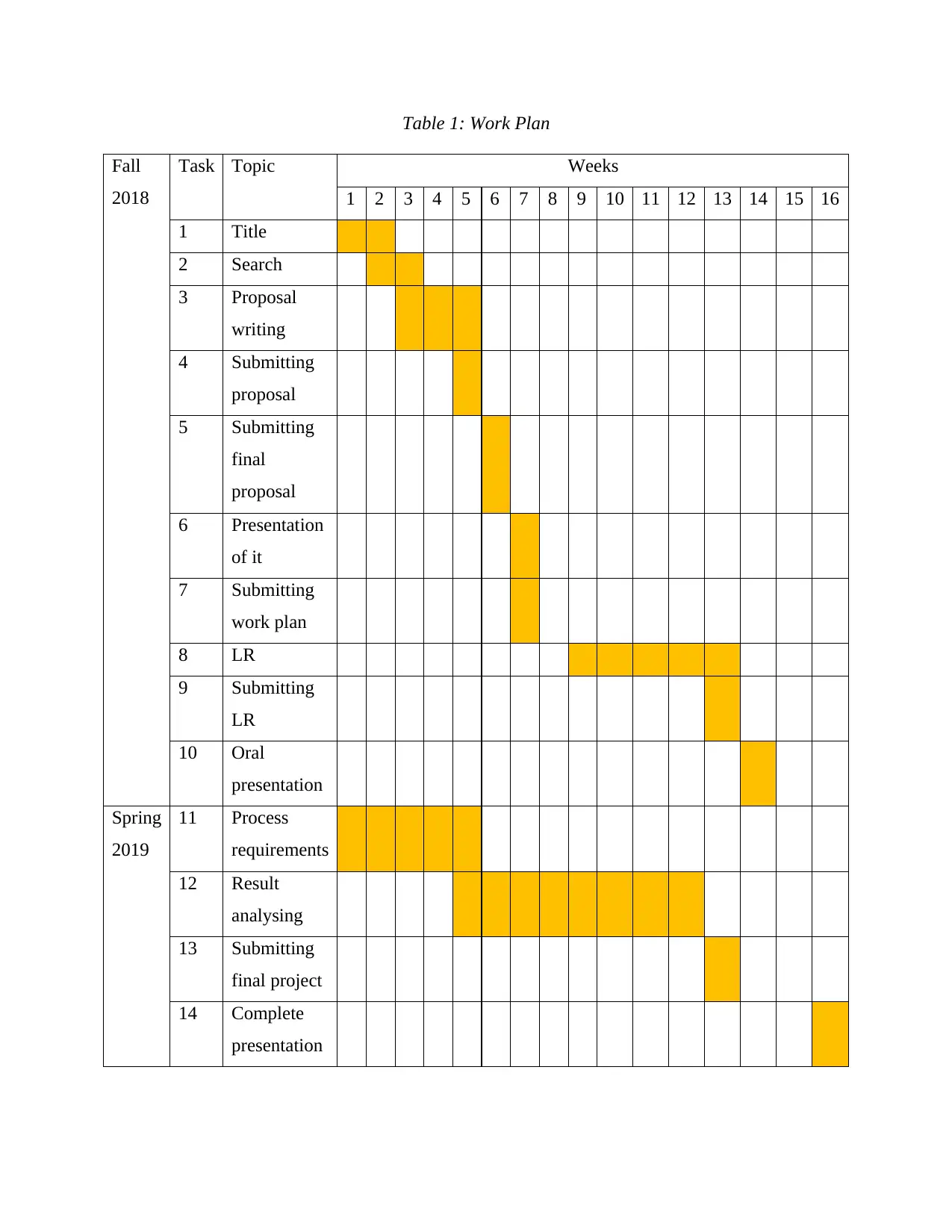
Table 1: Work Plan
Fall
2018
Task Topic Weeks
1 2 3 4 5 6 7 8 9 10 11 12 13 14 15 16
1 Title
2 Search
3 Proposal
writing
4 Submitting
proposal
5 Submitting
final
proposal
6 Presentation
of it
7 Submitting
work plan
8 LR
9 Submitting
LR
10 Oral
presentation
Spring
2019
11 Process
requirements
12 Result
analysing
13 Submitting
final project
14 Complete
presentation
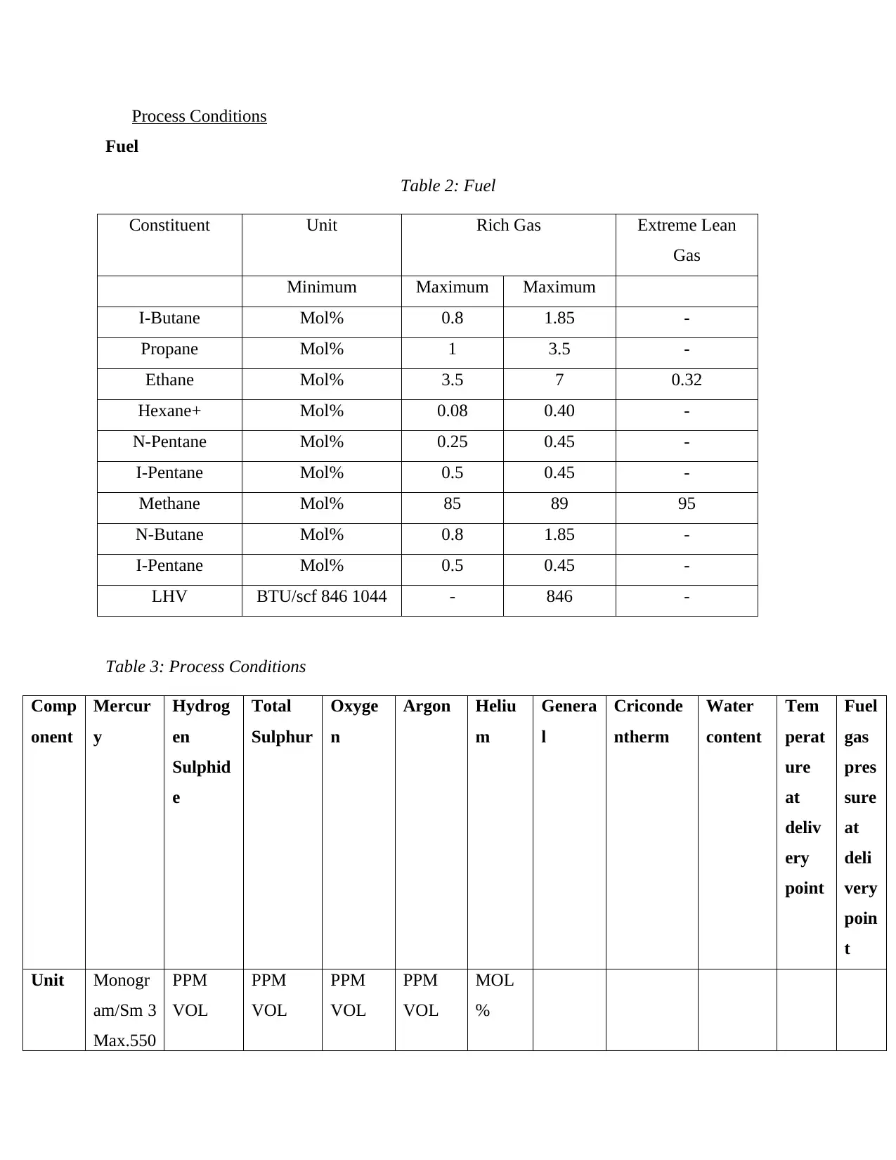
Process Conditions
Fuel
Table 2: Fuel
Constituent Unit Rich Gas Extreme Lean
Gas
Minimum Maximum Maximum
I-Butane Mol% 0.8 1.85 -
Propane Mol% 1 3.5 -
Ethane Mol% 3.5 7 0.32
Hexane+ Mol% 0.08 0.40 -
N-Pentane Mol% 0.25 0.45 -
I-Pentane Mol% 0.5 0.45 -
Methane Mol% 85 89 95
N-Butane Mol% 0.8 1.85 -
I-Pentane Mol% 0.5 0.45 -
LHV BTU/scf 846 1044 - 846 -
Table 3: Process Conditions
Comp
onent
Mercur
y
Hydrog
en
Sulphid
e
Total
Sulphur
Oxyge
n
Argon Heliu
m
Genera
l
Criconde
ntherm
Water
content
Tem
perat
ure
at
deliv
ery
point
Fuel
gas
pres
sure
at
deli
very
poin
t
Unit Monogr
am/Sm 3
Max.550
PPM
VOL
PPM
VOL
PPM
VOL
PPM
VOL
MOL
%
Fuel
Table 2: Fuel
Constituent Unit Rich Gas Extreme Lean
Gas
Minimum Maximum Maximum
I-Butane Mol% 0.8 1.85 -
Propane Mol% 1 3.5 -
Ethane Mol% 3.5 7 0.32
Hexane+ Mol% 0.08 0.40 -
N-Pentane Mol% 0.25 0.45 -
I-Pentane Mol% 0.5 0.45 -
Methane Mol% 85 89 95
N-Butane Mol% 0.8 1.85 -
I-Pentane Mol% 0.5 0.45 -
LHV BTU/scf 846 1044 - 846 -
Table 3: Process Conditions
Comp
onent
Mercur
y
Hydrog
en
Sulphid
e
Total
Sulphur
Oxyge
n
Argon Heliu
m
Genera
l
Criconde
ntherm
Water
content
Tem
perat
ure
at
deliv
ery
point
Fuel
gas
pres
sure
at
deli
very
poin
t
Unit Monogr
am/Sm 3
Max.550
PPM
VOL
PPM
VOL
PPM
VOL
PPM
VOL
MOL
%
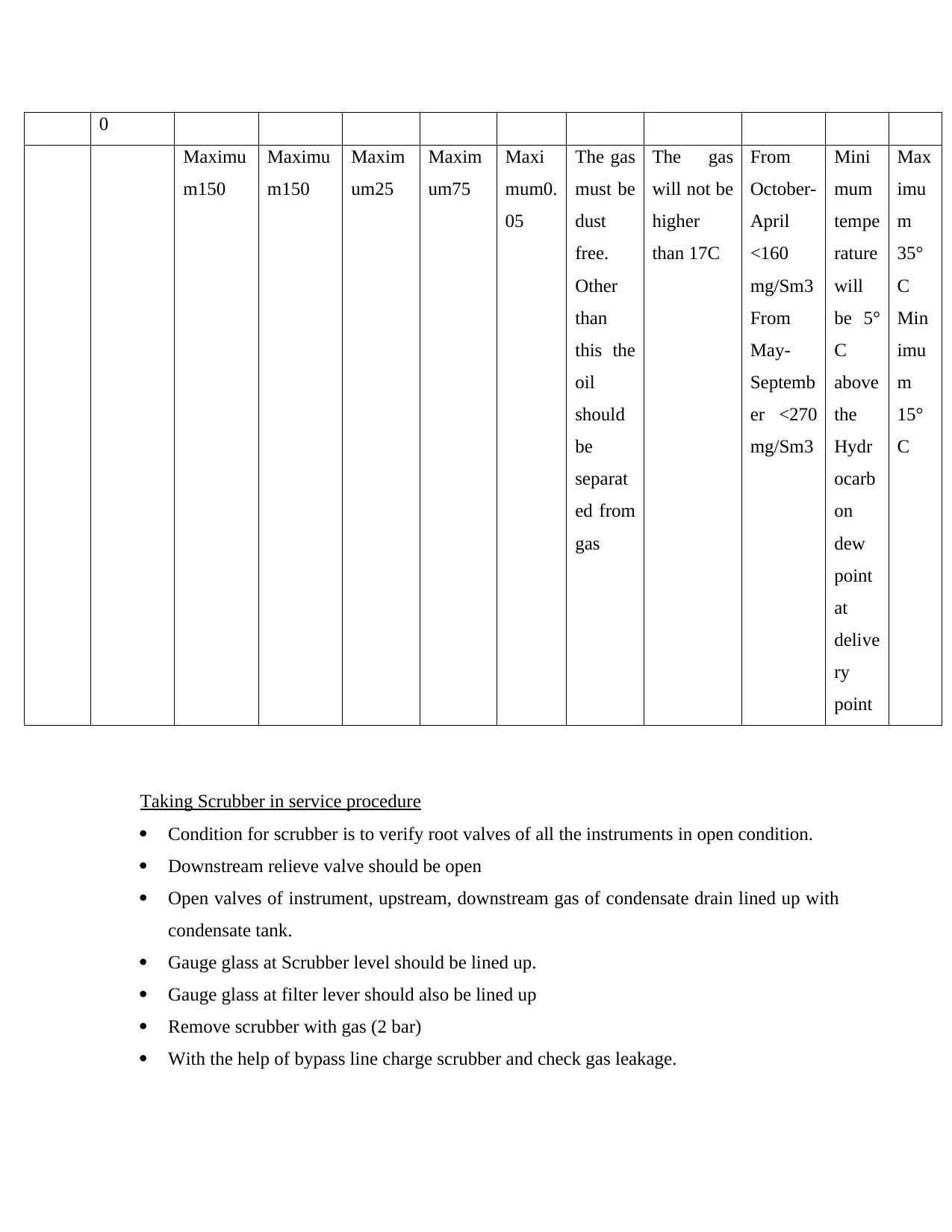
0
Maximu
m150
Maximu
m150
Maxim
um25
Maxim
um75
Maxi
mum0.
05
The gas
must be
dust
free.
Other
than
this the
oil
should
be
separat
ed from
gas
The gas
will not be
higher
than 17C
From
October-
April
<160
mg/Sm3
From
May-
Septemb
er <270
mg/Sm3
Mini
mum
tempe
rature
will
be 5°
C
above
the
Hydr
ocarb
on
dew
point
at
delive
ry
point
Max
imu
m
35°
C
Min
imu
m
15°
C
Taking Scrubber in service procedure
Condition for scrubber is to verify root valves of all the instruments in open condition.
Downstream relieve valve should be open
Open valves of instrument, upstream, downstream gas of condensate drain lined up with
condensate tank.
Gauge glass at Scrubber level should be lined up.
Gauge glass at filter lever should also be lined up
Remove scrubber with gas (2 bar)
With the help of bypass line charge scrubber and check gas leakage.
Maximu
m150
Maximu
m150
Maxim
um25
Maxim
um75
Maxi
mum0.
05
The gas
must be
dust
free.
Other
than
this the
oil
should
be
separat
ed from
gas
The gas
will not be
higher
than 17C
From
October-
April
<160
mg/Sm3
From
May-
Septemb
er <270
mg/Sm3
Mini
mum
tempe
rature
will
be 5°
C
above
the
Hydr
ocarb
on
dew
point
at
delive
ry
point
Max
imu
m
35°
C
Min
imu
m
15°
C
Taking Scrubber in service procedure
Condition for scrubber is to verify root valves of all the instruments in open condition.
Downstream relieve valve should be open
Open valves of instrument, upstream, downstream gas of condensate drain lined up with
condensate tank.
Gauge glass at Scrubber level should be lined up.
Gauge glass at filter lever should also be lined up
Remove scrubber with gas (2 bar)
With the help of bypass line charge scrubber and check gas leakage.
Secure Best Marks with AI Grader
Need help grading? Try our AI Grader for instant feedback on your assignments.
The optimum pressure to open inlet valve should be 30 bar and them O/L valve should be
open afterwards.
Taking WBH in service procedure
Root valves of all the instruments should be in open condition
Instrument air should be available and root valves of pneumatic gas line for PRV pilot
and valves of slam shut-off should be open.
Ensure that power supply to bath heater is available, inlet valve is open and both burner
shut-off valves should be closed.
Check gas mixing MOV position where MOV is in REMOTE.
Open valves of ignition gas near burner and main BRNS line (Mohammed, Gas Turbine
Efficiency, 2018).
Check leakage in system, gauge level of bath expansion tank is lined up where level is
more than 60% and then LPC emergency push button should be released.
Downstream pressure of PRV fuel gas is 1.5bar and pilot line 0.5bar
Ensure no alarm on DCS and local panel as well as control valve of control gas is at auto
on DCS.
Set-point of mixing valve should be 45°C and valve is at auto.
Burner flames should be stable and combustion is normal and then open outlet valve
Check that valve of burner control is controlling gradual increase in temperature of water
bath
Pressure reducing station with one valve to reduce pressure, one shut-off valve, one
NRV.
Layout
Plant layout is used where many physical means are located for a single process with a
main objective to ensure smooth flow of material, people, work and information. There are many
factors involved in designing a plant like economics, health and safety, maintenance,
transportation, future expansion, process operations and units (Albadi And et.al, 2018).
Factors involved in SA power plant designing are:
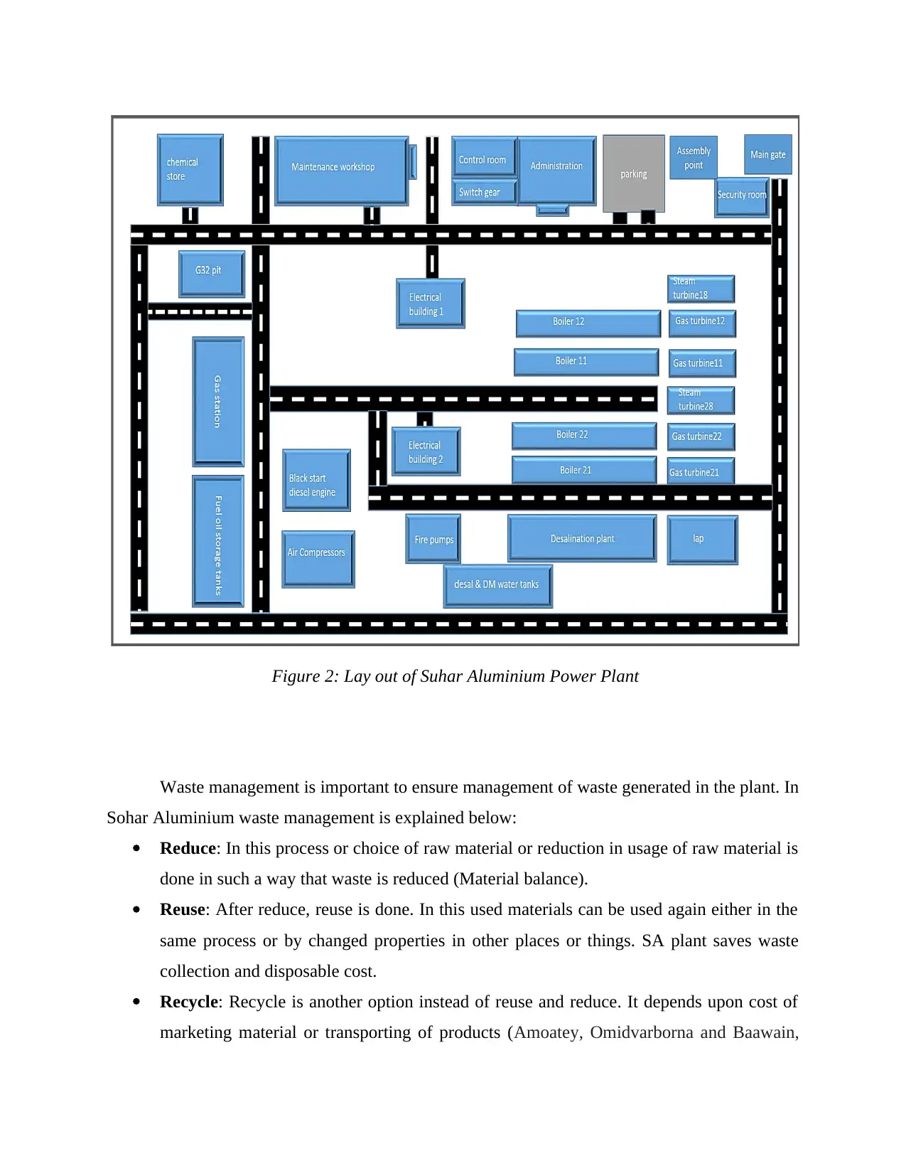
Office buildings and administration are included in plant located away from process area.
Storage tanks or units which process or handle toxic substances shouldn't be kept close to
process unit.
Fuel or gas stations, flammable material storage tanks should be located far away from
plant building or process units.
Utilities management building or control rooms location should be in a non-hazardous
area.
Automated emergency systems or fire stations should be located at the nearest point of
process unit area.
Unloading or loading area location should be decided in a strategic way.
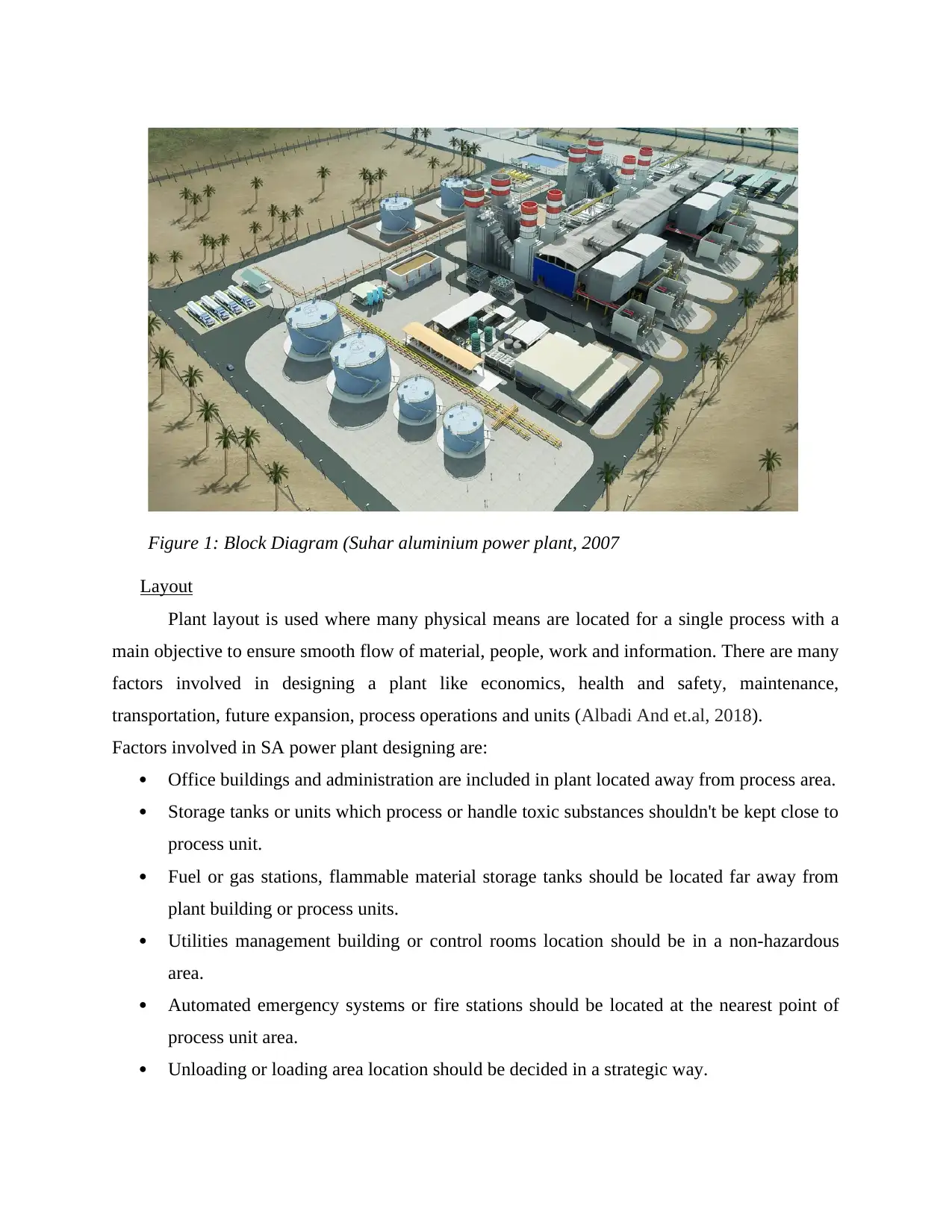
Figure 1: Block Diagram (Suhar aluminium power plant, 2007
Waste management is important to ensure management of waste generated in the plant. In
Sohar Aluminium waste management is explained below:
Reduce: In this process or choice of raw material or reduction in usage of raw material is
done in such a way that waste is reduced (Material balance).
Reuse: After reduce, reuse is done. In this used materials can be used again either in the
same process or by changed properties in other places or things. SA plant saves waste
collection and disposable cost.
Recycle: Recycle is another option instead of reuse and reduce. It depends upon cost of
marketing material or transporting of products (Amoatey, Omidvarborna and Baawain,
Figure 2: Lay out of Suhar Aluminium Power Plant
Paraphrase This Document
Need a fresh take? Get an instant paraphrase of this document with our AI Paraphraser
2018). Properties of material should not be changed in case of recycle to reduce use of
new raw materials.
Recovery: recovery is done from waste like in making fuel. It can also be used in
regaining strength or in treatment process.
Disposal: It is done in case of distribution of remaining waste that cannot be used,
recycled and are needed to be disposed like hazardous waste are needed to be disposed, if
not disposed it can create risk. Person involved in this should be trained in disposing,
handling and transporting.
Environmental impact
In order to consider various environmental impacts during the development of the
Aluminium plant is one of the major concern. As this project generates the power and electricity
using fuel and gas so it may negatively impacts on the environment which leads to the poor
health of the people. Various environmental issues are included in developing a power plant such
as:
Production of harmful gases due to the combustion of fuel.
Formation of the oily water pits.
High temperature of water
Main pit
Emission of harmful gases such as Carbon dioxide, SO2, NOX, Hydrocarbon etc.
All such issues lead to the great impact on the environment. So in order to maintain such
environmental problems, good quality of burners is used in gas turbines which emit less gases.
This special burner is called as EV (Environment burner) which lowers the temperature of the
flame at about 500k. Also, additive water is used at the time of Fuel oil emulsion that results in
low emission of gases. The fuel emits NO2, so they keep the gas turbine in normal load in order
to reduce the gas flow (STS Company, Monitoring and Operation Book, 2007). Control room or
chemists generally measures the the limit of the NOX in Oman. As the power plant machine
produces 30 to 40 of the total 150mg/Nm3. Also, NOX and SO2 react with water and oxygen to
produce sulphuric and Nitric Acid.
NOX+SO2+O2+H2O =H2SO4+HNO (Acid Rain)
Also, oily waste water is produced from the pits of Block1 and 2 whcich are suplied by
oily water separator. This separated oil is disposed with the help of either trucks or barrels.
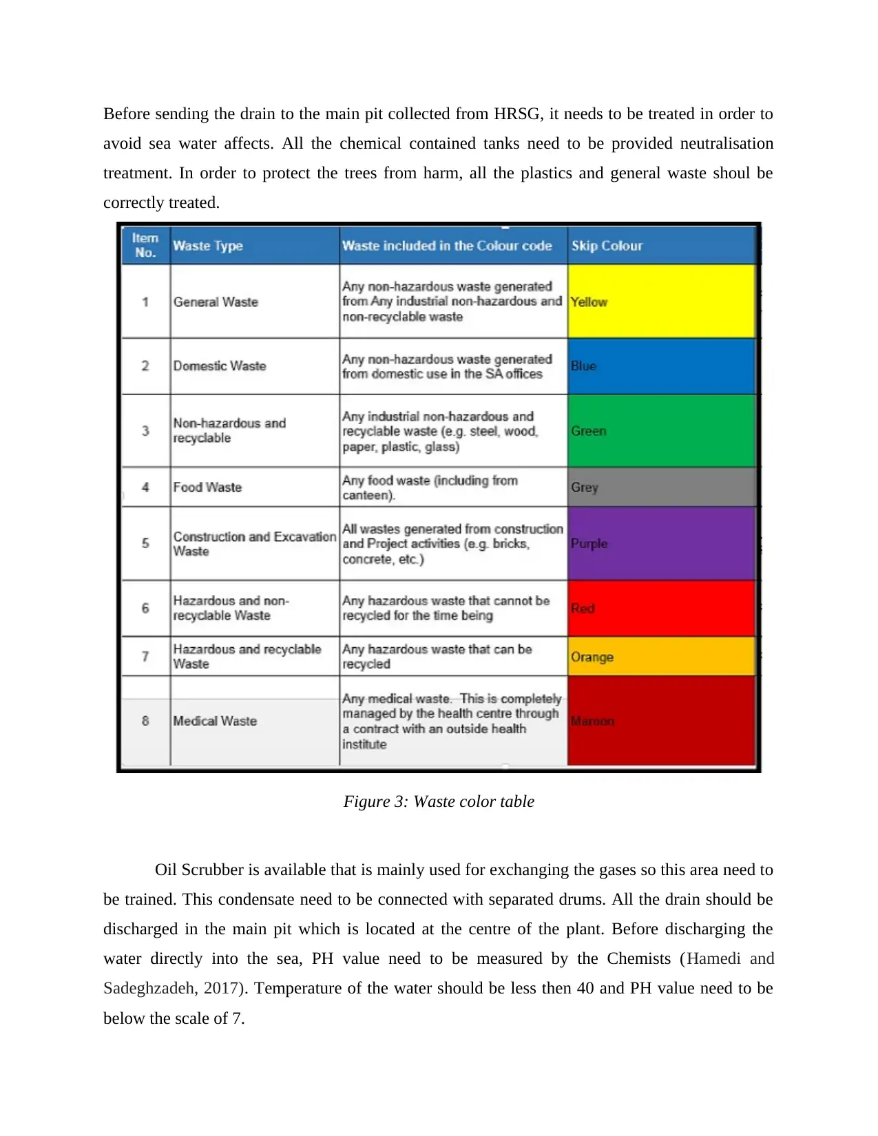
Before sending the drain to the main pit collected from HRSG, it needs to be treated in order to
avoid sea water affects. All the chemical contained tanks need to be provided neutralisation
treatment. In order to protect the trees from harm, all the plastics and general waste shoul be
correctly treated.
Figure 3: Waste color table
Oil Scrubber is available that is mainly used for exchanging the gases so this area need to
be trained. This condensate need to be connected with separated drums. All the drain should be
discharged in the main pit which is located at the centre of the plant. Before discharging the
water directly into the sea, PH value need to be measured by the Chemists (Hamedi and
Sadeghzadeh, 2017). Temperature of the water should be less then 40 and PH value need to be
below the scale of 7.
Chemical should be placed securely in chemical store which contains fire frightening
system and exhaust fan.
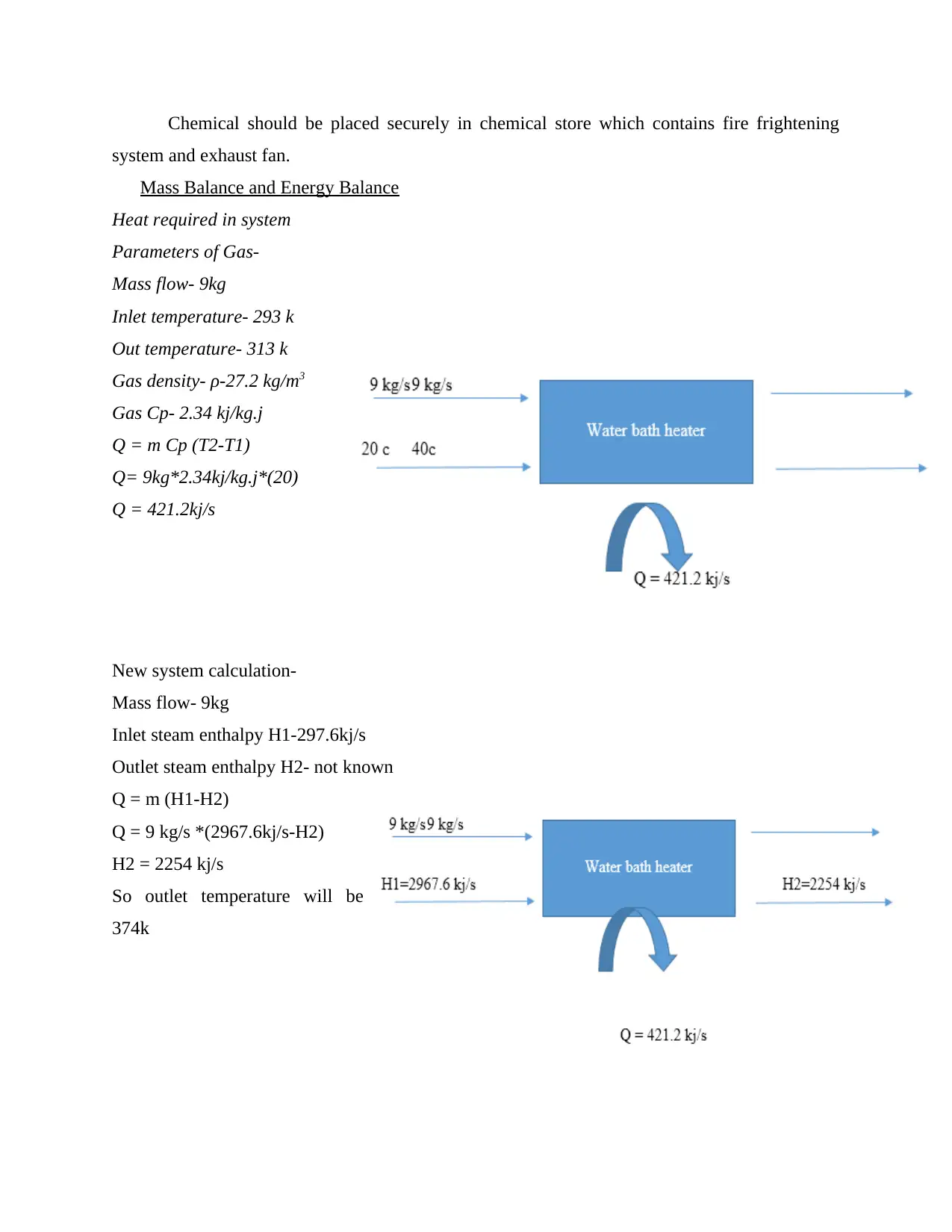
Mass Balance and Energy Balance
Heat required in system
Parameters of Gas-
Mass flow- 9kg
Inlet temperature- 293 k
Out temperature- 313 k
Gas density- ρ-27.2 kg/m3
Gas Cp- 2.34 kj/kg.j
Q = m Cp (T2-T1)
Q= 9kg*2.34kj/kg.j*(20)
Q = 421.2kj/s
New system calculation-
Mass flow- 9kg
Inlet steam enthalpy H1-297.6kj/s
Outlet steam enthalpy H2- not known
Q = m (H1-H2)
Q = 9 kg/s *(2967.6kj/s-H2)
H2 = 2254 kj/s
So outlet temperature will be
374k
Secure Best Marks with AI Grader
Need help grading? Try our AI Grader for instant feedback on your assignments.
New system efficiency as compared to old system efficiency. As operations of old system
includes various calculations:
In order to produce 1 M/Watt in the turbine of the gas, old system require to produce 3.5 T/H.
However, Bath heater generally consumes 0.073 kg/s in order to produce 421.2 Kj/sec. So it was
found that after calculations, 0.073 kg/s is basically used to produce 1.3M/Watt.
Power Flow Diagram
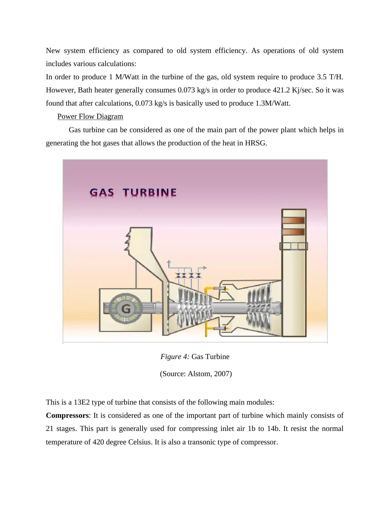
Gas turbine can be considered as one of the main part of the power plant which helps in
generating the hot gases that allows the production of the heat in HRSG.
This is a 13E2 type of turbine that consists of the following main modules:
Compressors: It is considered as one of the important part of turbine which mainly consists of
21 stages. This part is generally used for compressing inlet air 1b to 14b. It resist the normal
temperature of 420 degree Celsius. It is also a transonic type of compressor.
Figure 4: Gas Turbine
(Source: Alstom, 2007)
Combustor: This component is used for increasing the temperature from 420 degree to 1080
degree Celsius (Knoepfel, 2017. ). This can only be heated with the help of burning Fuel or gas
oil. With the flow of temperature to 9.5 kg/sec, air pressure is compressed up-to 25b which
generally maintains the temperature of 35 to 40 degree Celsius.
Turbine: This component is mainly used to exchange the hot gases into the boiler which
contains the temperature of 500 degree Celsius.
Generator: It helps in generating the electrical energy with the help of burning fuel and gases. It
mainly produces 15 Kv capacity of energy which further supply the power to grid and smelter.
There is also one more component is used that is called as Lube oil and this is generally
used as lubricant.
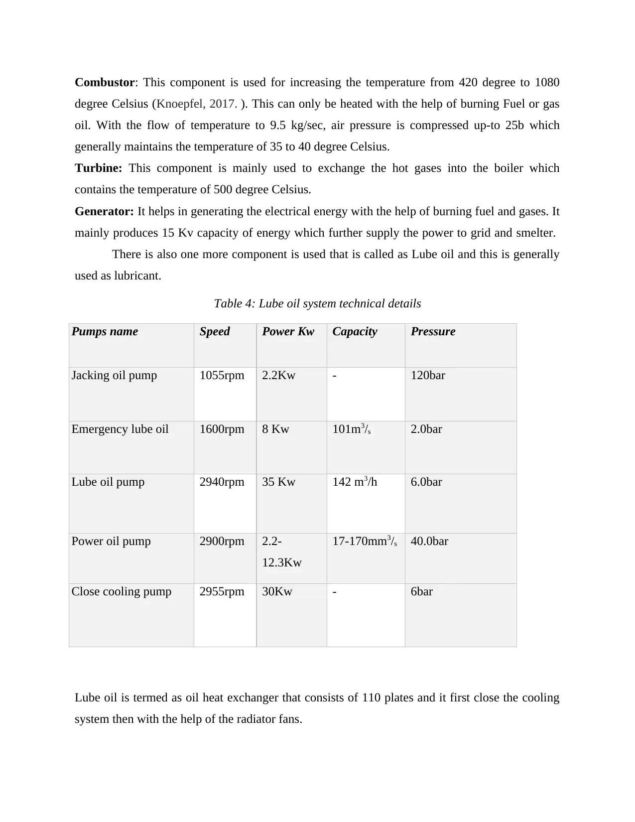
Table 4: Lube oil system technical details
Pumps name Speed Power Kw Capacity Pressure
Jacking oil pump 1055rpm 2.2Kw - 120bar
Emergency lube oil 1600rpm 8 Kw 101m3/s 2.0bar
Lube oil pump 2940rpm 35 Kw 142 m3/h 6.0bar
Power oil pump 2900rpm 2.2-
12.3Kw
17-170mm3/s 40.0bar
Close cooling pump 2955rpm 30Kw - 6bar
Lube oil is termed as oil heat exchanger that consists of 110 plates and it first close the cooling
system then with the help of the radiator fans.
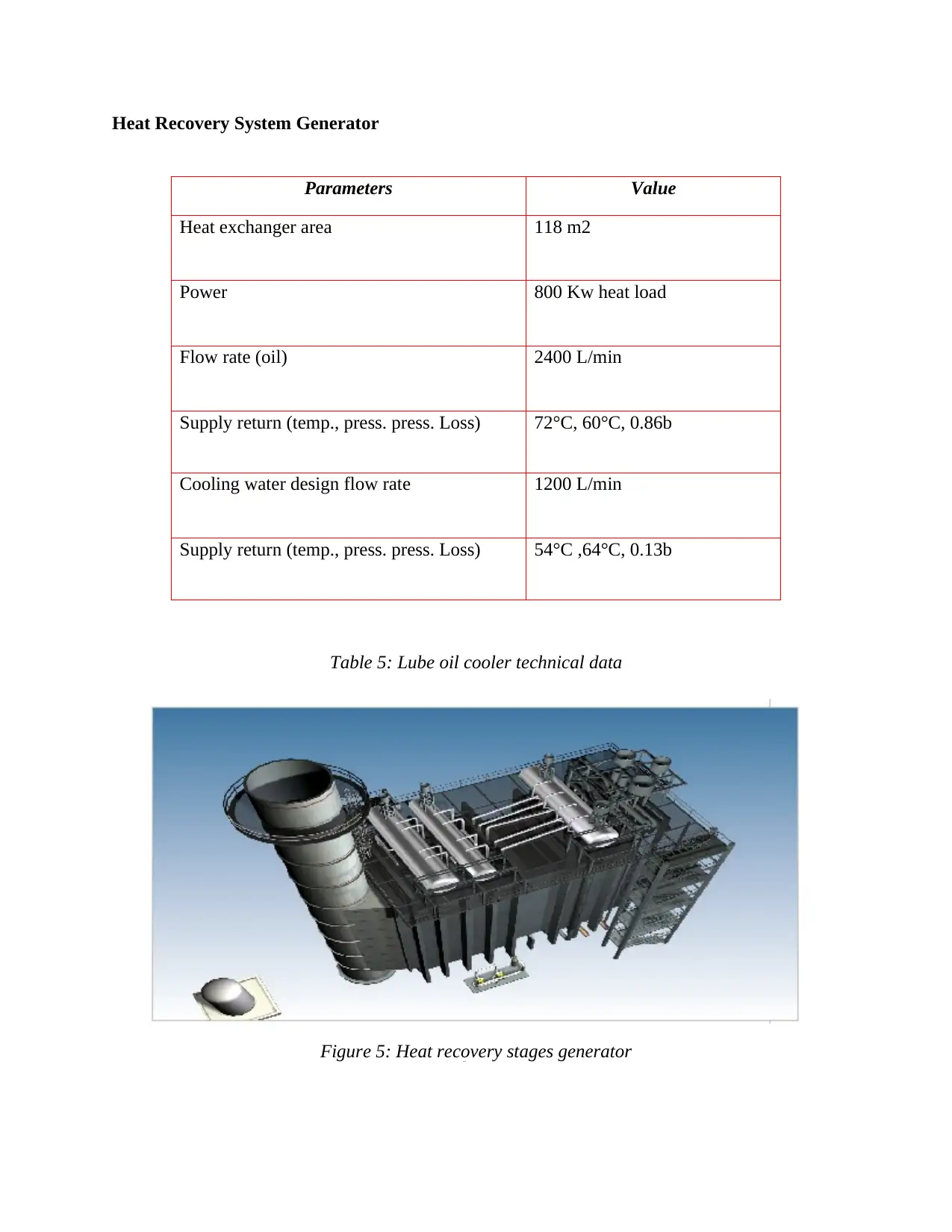
Heat Recovery System Generator
Parameters Value
Heat exchanger area 118 m2
Power 800 Kw heat load
Flow rate (oil) 2400 L/min
Supply return (temp., press. press. Loss) 72°C, 60°C, 0.86b
Cooling water design flow rate 1200 L/min
Supply return (temp., press. press. Loss) 54°C ,64°C, 0.13b
Table 5: Lube oil cooler technical data
Figure5:Figure 5: Heat recovery stages generator
Paraphrase This Document
Need a fresh take? Get an instant paraphrase of this document with our AI Paraphraser
Boiler can be considered as one of the important part of the plant as it passes the gas
coming from the turbine in order to generate high and low pressure steam for steam turbine. In
order to increase the temperature of water slowly from 60 to 260 degree Celsius High pressure
steam works with evaporator. The temperature is increased in first super heater and then in
second one 400 to 450 degree.
HP system is placed at Upper side of LP system to produce HP steam for HP steam
turbine where hot gases are exchanged. LP steam flow is generally 52 t/h which is used to
produce LP steam for LP steam turbine (Energy 2000). It is situated near HRSG. This can be
considered as two-pressure system in order to consume hot gases from gas turbine. HRSG
double pressure unit consists of two boiler system that allows the circulation of water and steam
in each system. The outlet and inlet duct are generally connected with GT ( Gas Turbine).
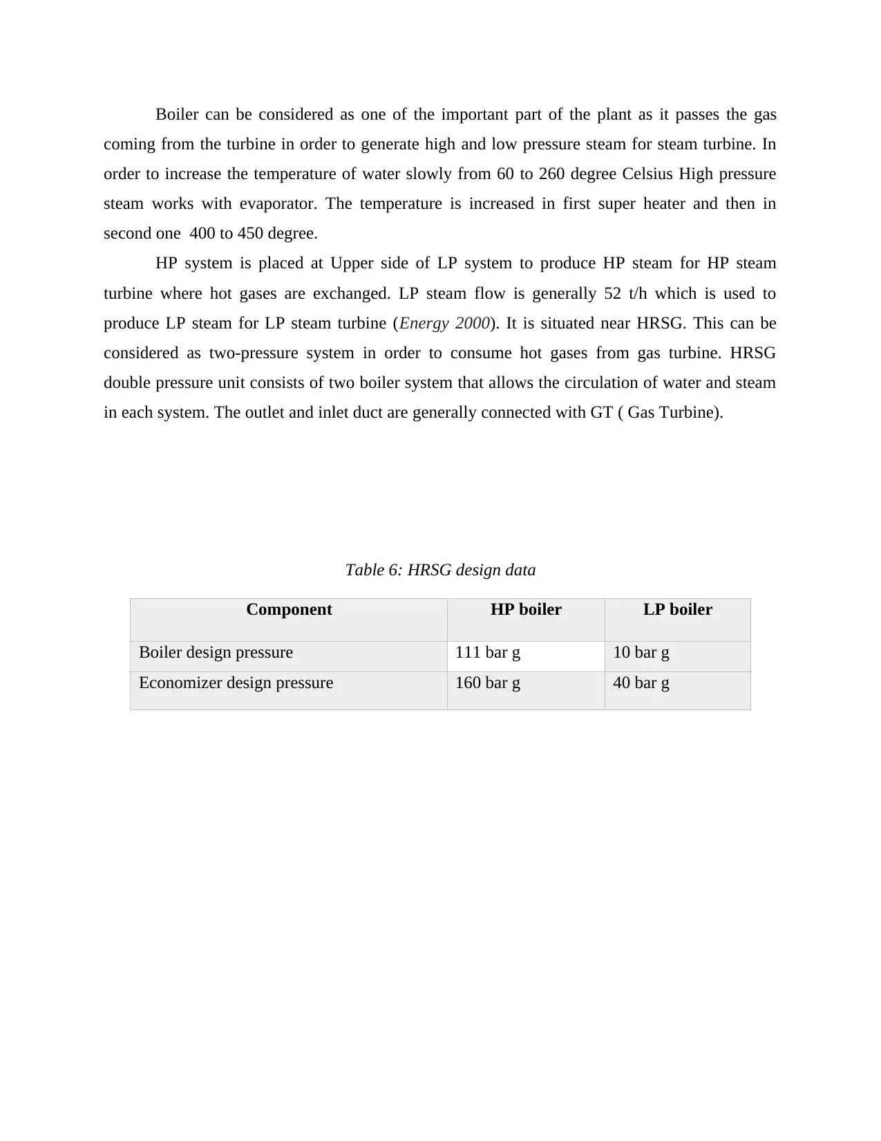
Table 6: HRSG design data
Component HP boiler LP boiler
Boiler design pressure 111 bar g 10 bar g
Economizer design pressure 160 bar g 40 bar g
Max outlet steam pressure 105 bar g 8 bar g
Hydro pressure - boiler 166.5 bar g 15 bar g
Hydro pressure – economizer 240 bar g 60 bar g
Max outlet steam temperature 550°C 290°C
Heating surface area 89455 m2 39899 m2
Block down Tank System
This system is mainly used to collect all the Heat recovery stages from drains. Such are
as follows:
Continues blow down Drums
Intermittent Blow Down drums Water and Steam Drains
SF (Supplementary firing)
It is a duct burner that helps in maximising the temperature inside the boiler and with the
help of the GT. It consists of the various components such as Flow meter, Air Fans 2 scanner,
and gas control value of fuel and Duct burner. SF also includes few more parts that are Pilot gas
pressure transmitter, supply lines and BMS to control the burner.
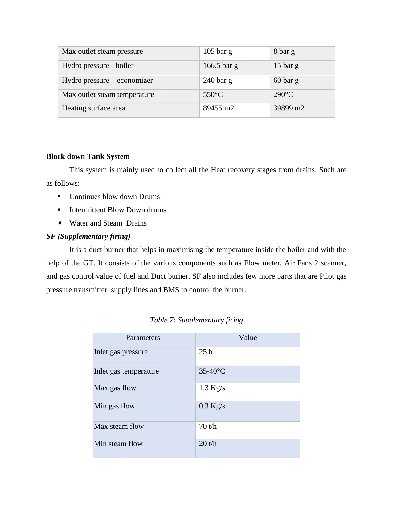
Table 7: Supplementary firing
Parameters Value
Inlet gas pressure 25 b
Inlet gas temperature 35-40°C
Max gas flow 1.3 Kg/s
Min gas flow 0.3 Kg/s
Max steam flow 70 t/h
Min steam flow 20 t/h
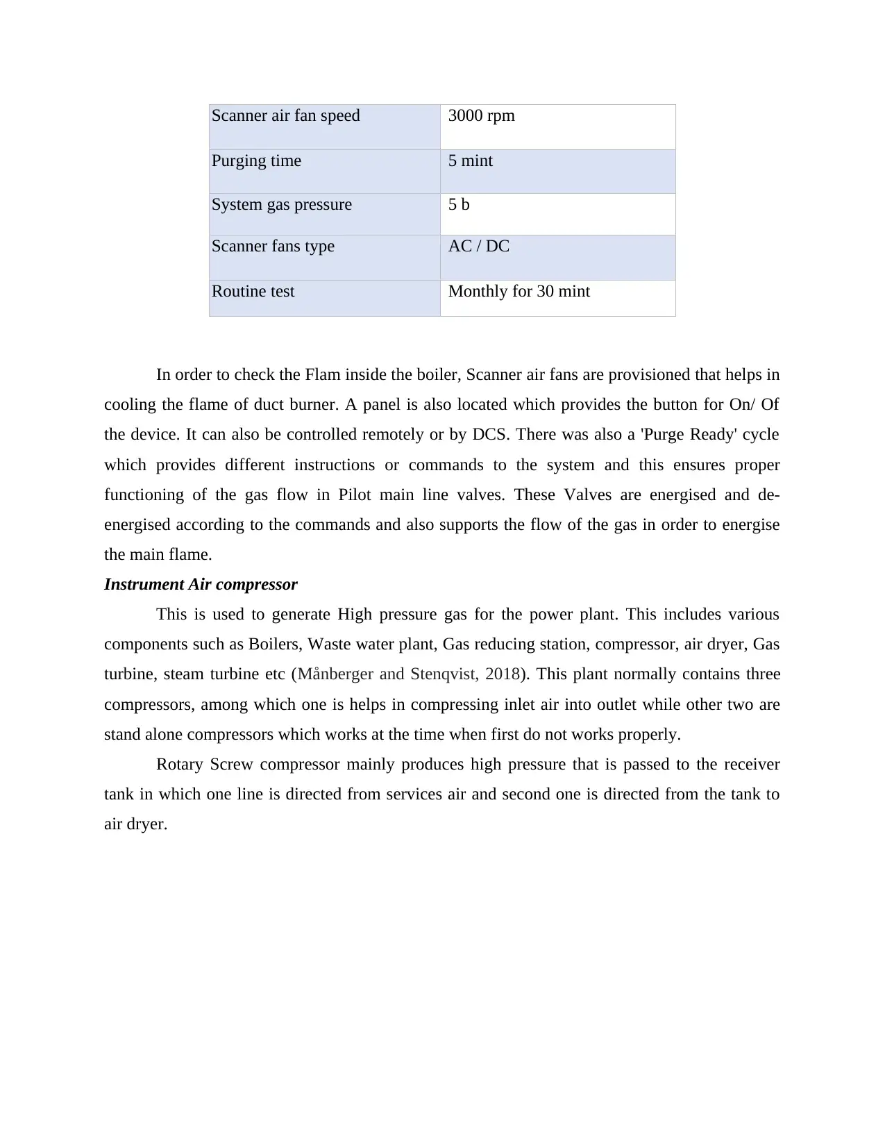
Scanner air fan speed 3000 rpm
Purging time 5 mint
System gas pressure 5 b
Scanner fans type AC / DC
Routine test Monthly for 30 mint
In order to check the Flam inside the boiler, Scanner air fans are provisioned that helps in
cooling the flame of duct burner. A panel is also located which provides the button for On/ Of
the device. It can also be controlled remotely or by DCS. There was also a 'Purge Ready' cycle
which provides different instructions or commands to the system and this ensures proper
functioning of the gas flow in Pilot main line valves. These Valves are energised and de-
energised according to the commands and also supports the flow of the gas in order to energise
the main flame.
Instrument Air compressor
This is used to generate High pressure gas for the power plant. This includes various
components such as Boilers, Waste water plant, Gas reducing station, compressor, air dryer, Gas
turbine, steam turbine etc (Månberger and Stenqvist, 2018). This plant normally contains three
compressors, among which one is helps in compressing inlet air into outlet while other two are
stand alone compressors which works at the time when first do not works properly.
Rotary Screw compressor mainly produces high pressure that is passed to the receiver
tank in which one line is directed from services air and second one is directed from the tank to
air dryer.
Secure Best Marks with AI Grader
Need help grading? Try our AI Grader for instant feedback on your assignments.
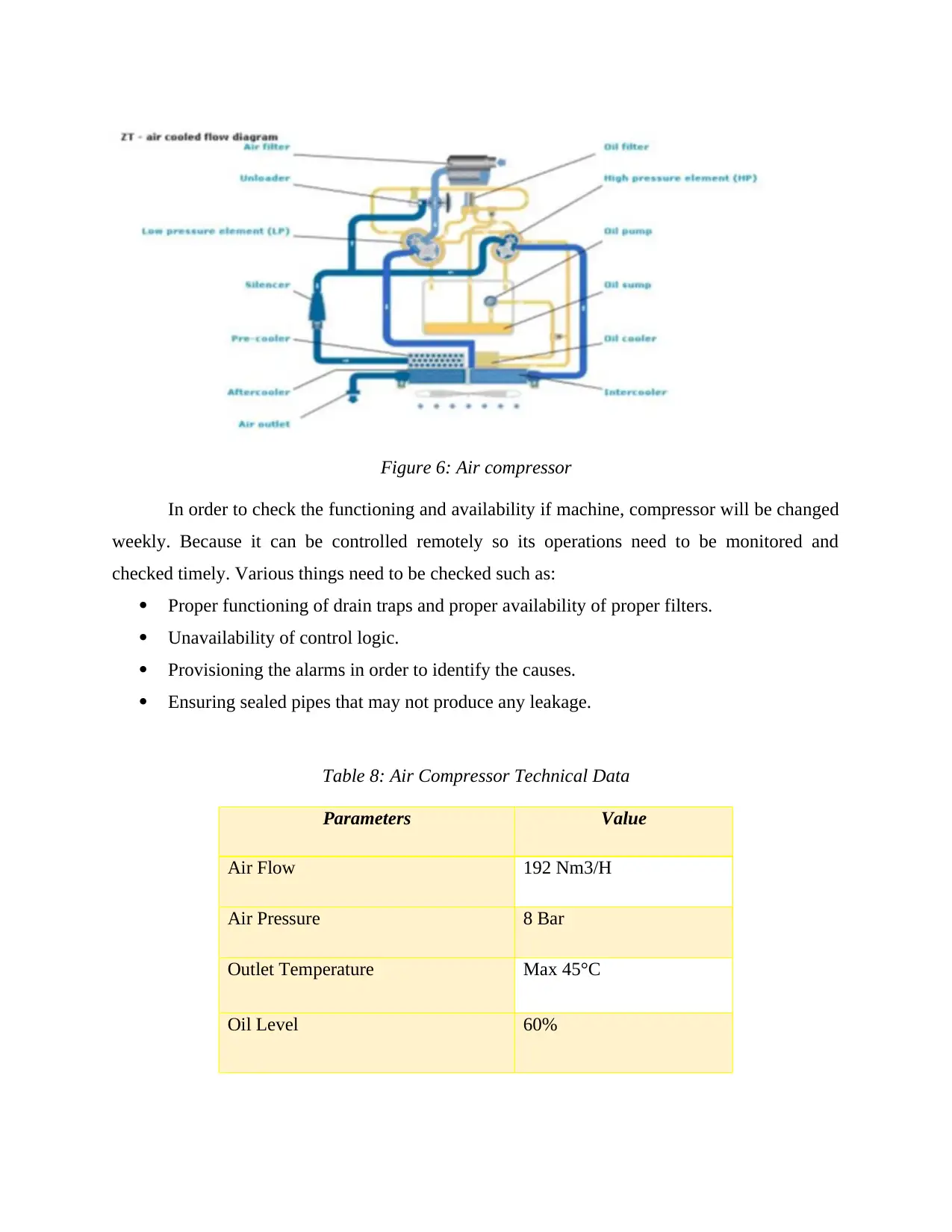
Figure 6: Air compressor
In order to check the functioning and availability if machine, compressor will be changed
weekly. Because it can be controlled remotely so its operations need to be monitored and
checked timely. Various things need to be checked such as:
Proper functioning of drain traps and proper availability of proper filters.
Unavailability of control logic.
Provisioning the alarms in order to identify the causes.
Ensuring sealed pipes that may not produce any leakage.
Table 8: Air Compressor Technical Data
Parameters Value
Air Flow 192 Nm3/H
Air Pressure 8 Bar
Outlet Temperature Max 45°C
Oil Level 60%
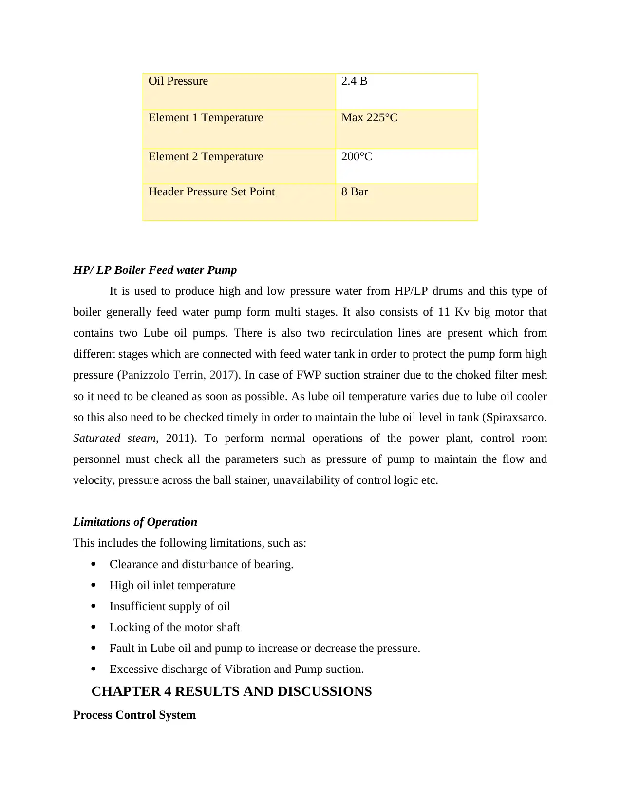
Oil Pressure 2.4 B
Element 1 Temperature Max 225°C
Element 2 Temperature 200°C
Header Pressure Set Point 8 Bar
HP/ LP Boiler Feed water Pump
It is used to produce high and low pressure water from HP/LP drums and this type of
boiler generally feed water pump form multi stages. It also consists of 11 Kv big motor that
contains two Lube oil pumps. There is also two recirculation lines are present which from
different stages which are connected with feed water tank in order to protect the pump form high
pressure (Panizzolo Terrin, 2017). In case of FWP suction strainer due to the choked filter mesh
so it need to be cleaned as soon as possible. As lube oil temperature varies due to lube oil cooler
so this also need to be checked timely in order to maintain the lube oil level in tank (Spiraxsarco.
Saturated steam, 2011). To perform normal operations of the power plant, control room
personnel must check all the parameters such as pressure of pump to maintain the flow and
velocity, pressure across the ball stainer, unavailability of control logic etc.
Limitations of Operation
This includes the following limitations, such as:
Clearance and disturbance of bearing.
High oil inlet temperature
Insufficient supply of oil
Locking of the motor shaft
Fault in Lube oil and pump to increase or decrease the pressure.
Excessive discharge of Vibration and Pump suction.
CHAPTER 4 RESULTS AND DISCUSSIONS
Process Control System
Every system need to be initialised after applications of data and logics into it. Such
logics and programs helps in controlling all the functions of the system. So various process
instruments are connected to ensure the accuracy and efficiency of work within the plant. In this
plant various control devices are used to make it more efficient power plant as a whole. Such
devices are Temperature controller, Flow transmitter, control values and Purging shut off values
etc. These all instrument carries different functioning so functions of each part of the
instrumental devices are as follows:
Automatic release vent: This is mainly helps in releasing the air in the pipeline which is mainly
aimed at preventing the flow of disturbance and this assure that there will be no any air trapped
in the pipe line which causes lots of problems and this prevents the system to work smoothly.
Also the valve which is equipped in this system is solenoid valve
Temperature transmitters: This is also used to control steam temperature and also helps in
changing the temperature of control room accordingly. Steam temperature may also effects heat
transfer coefficient and heat-transfer rate which generally limits from 30 to 60 degree Celcius at
high limit.
Pressure Transmitter: This can be considered as one of the important part as it helps in in
increasing or decreasing the pressure of the plant. There are 4 bars in maintaining high and low
temperature which consists of 2.5 bars one by one.
Purging shut Off Value: Inserting the gas inside the pipeline in order to function the generator
is one of the most important thing. This is mainly performed to prevent the outage from any
toxic gases or flammable gases present in the valves. The motor is inserted to control the shut on
and off the inserted gas. For example, Nitrogen gas is mostly used as a inserting gas.
Flow control valve: This is used to control the flow of steam which is inserted in the system.
This is also used to control the quantity of steam flow as it supports the solenoid valve in order to
supply the air.
Differential pressure transmitter: It is used to measure the upstream and downstream pressure
from the transmitter. This allows chemist in understanding the differences of pressure and
therefore indicates the need to clean the filter.
Maintenance requirement
Maintenance can be considered as one of the important part of the industry as it helps in
proper maintenance of the power plant and also helps in sustaining the plant for longer time. It
Paraphrase This Document
Need a fresh take? Get an instant paraphrase of this document with our AI Paraphraser
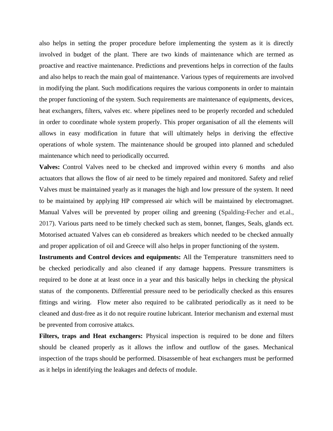
also helps in setting the proper procedure before implementing the system as it is directly
involved in budget of the plant. There are two kinds of maintenance which are termed as
proactive and reactive maintenance. Predictions and preventions helps in correction of the faults
and also helps to reach the main goal of maintenance. Various types of requirements are involved
in modifying the plant. Such modifications requires the various components in order to maintain
the proper functioning of the system. Such requirements are maintenance of equipments, devices,
heat exchangers, filters, valves etc. where pipelines need to be properly recorded and scheduled
in order to coordinate whole system properly. This proper organisation of all the elements will
allows in easy modification in future that will ultimately helps in deriving the effective
operations of whole system. The maintenance should be grouped into planned and scheduled
maintenance which need to periodically occurred.
Valves: Control Valves need to be checked and improved within every 6 months and also
actuators that allows the flow of air need to be timely repaired and monitored. Safety and relief
Valves must be maintained yearly as it manages the high and low pressure of the system. It need
to be maintained by applying HP compressed air which will be maintained by electromagnet.
Manual Valves will be prevented by proper oiling and greening (Spalding-Fecher and et.al.,
2017). Various parts need to be timely checked such as stem, bonnet, flanges, Seals, glands ect.
Motorised actuated Valves can eb considered as breakers which needed to be checked annually
and proper application of oil and Greece will also helps in proper functioning of the system.
Instruments and Control devices and equipments: All the Temperature transmitters need to
be checked periodically and also cleaned if any damage happens. Pressure transmitters is
required to be done at at least once in a year and this basically helps in checking the physical
status of the components. Differential pressure need to be periodically checked as this ensures
fittings and wiring. Flow meter also required to be calibrated periodically as it need to be
cleaned and dust-free as it do not require routine lubricant. Interior mechanism and external must
be prevented from corrosive attakcs.
Filters, traps and Heat exchangers: Physical inspection is required to be done and filters
should be cleaned properly as it allows the inflow and outflow of the gases. Mechanical
inspection of the traps should be performed. Disassemble of heat exchangers must be performed
as it helps in identifying the leakages and defects of module.
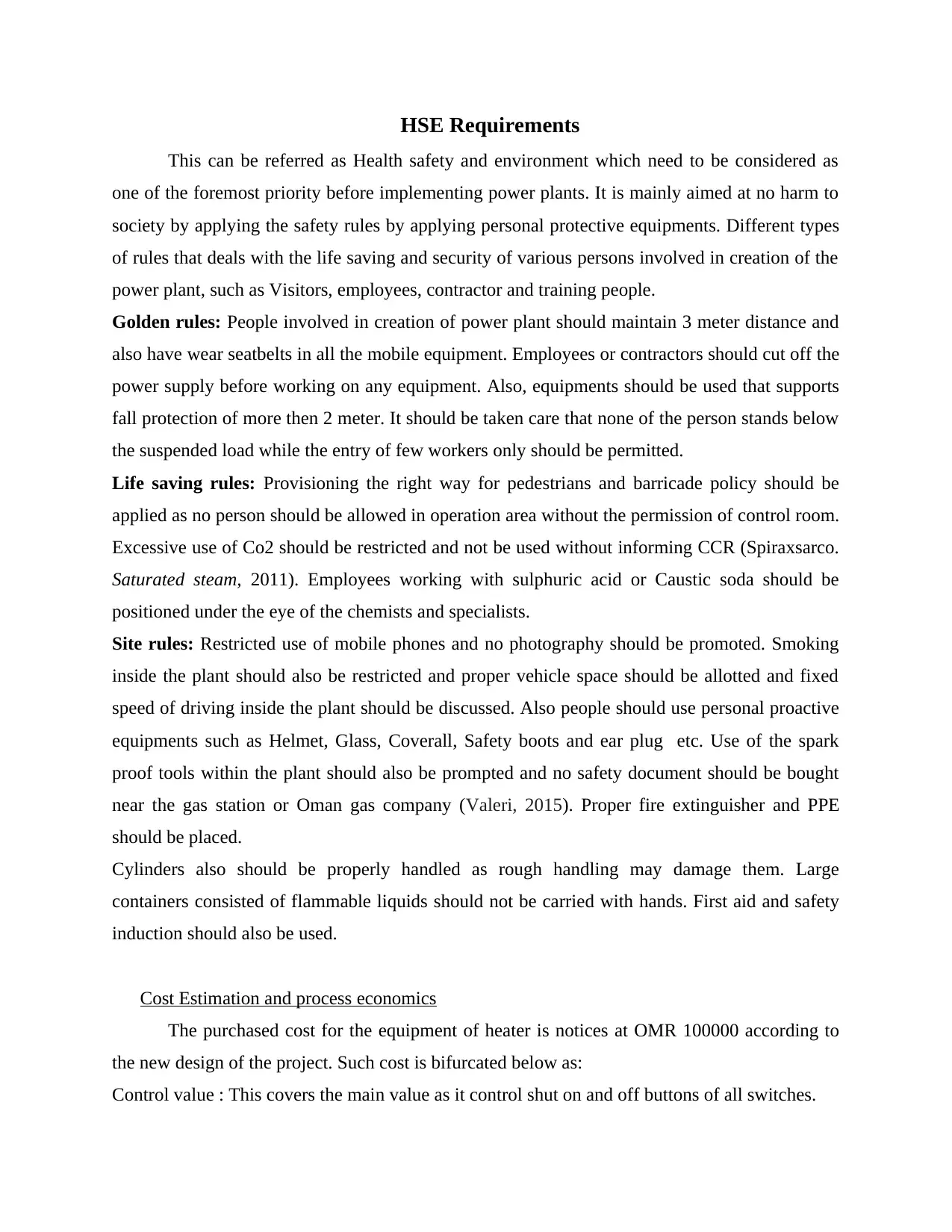
HSE Requirements
This can be referred as Health safety and environment which need to be considered as
one of the foremost priority before implementing power plants. It is mainly aimed at no harm to
society by applying the safety rules by applying personal protective equipments. Different types
of rules that deals with the life saving and security of various persons involved in creation of the
power plant, such as Visitors, employees, contractor and training people.
Golden rules: People involved in creation of power plant should maintain 3 meter distance and
also have wear seatbelts in all the mobile equipment. Employees or contractors should cut off the
power supply before working on any equipment. Also, equipments should be used that supports
fall protection of more then 2 meter. It should be taken care that none of the person stands below
the suspended load while the entry of few workers only should be permitted.
Life saving rules: Provisioning the right way for pedestrians and barricade policy should be
applied as no person should be allowed in operation area without the permission of control room.
Excessive use of Co2 should be restricted and not be used without informing CCR (Spiraxsarco.
Saturated steam, 2011). Employees working with sulphuric acid or Caustic soda should be
positioned under the eye of the chemists and specialists.
Site rules: Restricted use of mobile phones and no photography should be promoted. Smoking
inside the plant should also be restricted and proper vehicle space should be allotted and fixed
speed of driving inside the plant should be discussed. Also people should use personal proactive
equipments such as Helmet, Glass, Coverall, Safety boots and ear plug etc. Use of the spark
proof tools within the plant should also be prompted and no safety document should be bought
near the gas station or Oman gas company (Valeri, 2015). Proper fire extinguisher and PPE
should be placed.
Cylinders also should be properly handled as rough handling may damage them. Large
containers consisted of flammable liquids should not be carried with hands. First aid and safety
induction should also be used.
Cost Estimation and process economics
The purchased cost for the equipment of heater is notices at OMR 100000 according to
the new design of the project. Such cost is bifurcated below as:
Control value : This covers the main value as it control shut on and off buttons of all switches.
Bath Heaters: This contains various components which works with the help of another
component so it involves the major cost.
Instrumentation: This is a smaller cost that mainly consists of all such interconnected cost
involved in maintenance.
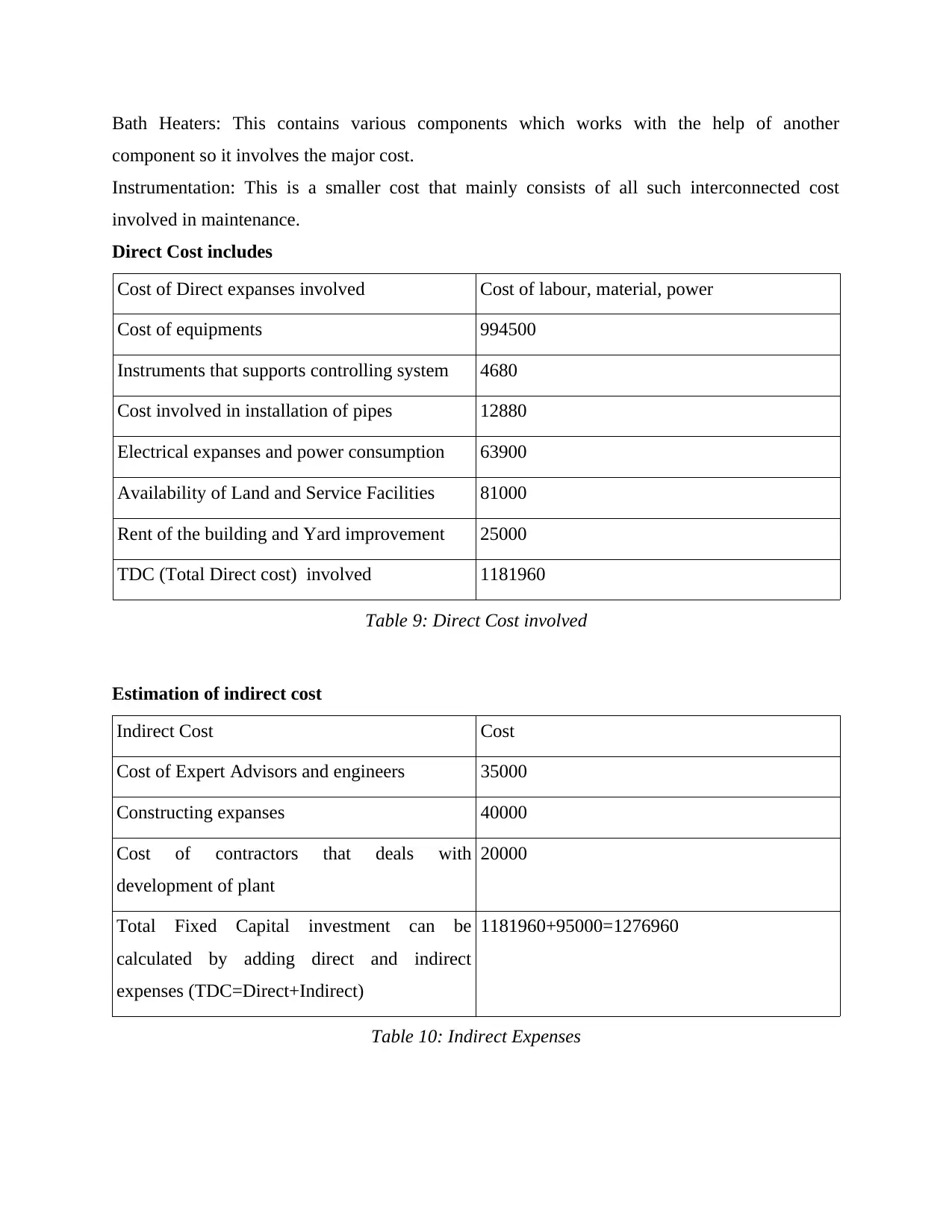
Direct Cost includes
Cost of Direct expanses involved Cost of labour, material, power
Cost of equipments 994500
Instruments that supports controlling system 4680
Cost involved in installation of pipes 12880
Electrical expanses and power consumption 63900
Availability of Land and Service Facilities 81000
Rent of the building and Yard improvement 25000
TDC (Total Direct cost) involved 1181960
Table 9: Direct Cost involved
Estimation of indirect cost
Indirect Cost Cost
Cost of Expert Advisors and engineers 35000
Constructing expanses 40000
Cost of contractors that deals with
development of plant
20000
Total Fixed Capital investment can be
calculated by adding direct and indirect
expenses (TDC=Direct+Indirect)
1181960+95000=1276960
Table 10: Indirect Expenses
Secure Best Marks with AI Grader
Need help grading? Try our AI Grader for instant feedback on your assignments.
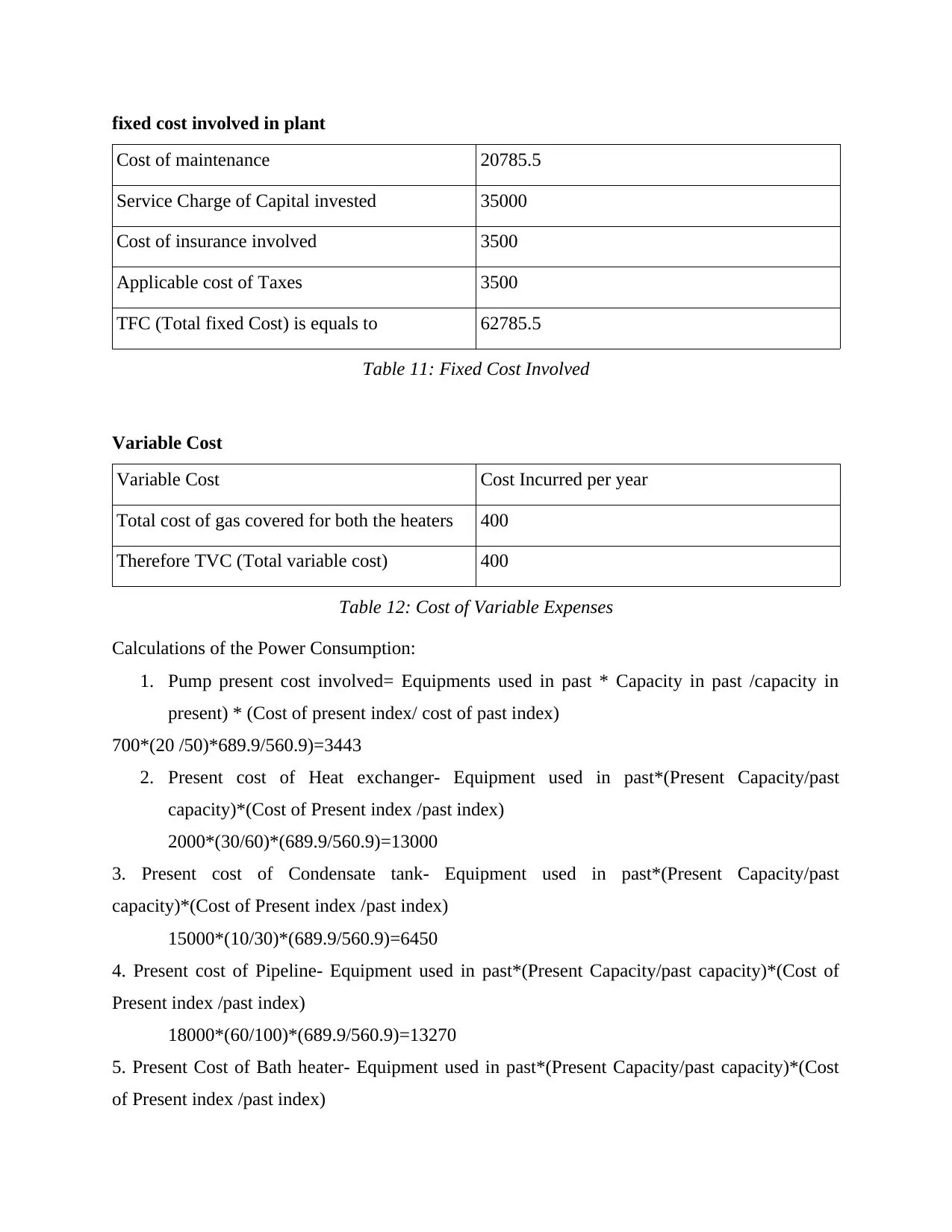
fixed cost involved in plant
Cost of maintenance 20785.5
Service Charge of Capital invested 35000
Cost of insurance involved 3500
Applicable cost of Taxes 3500
TFC (Total fixed Cost) is equals to 62785.5
Table 11: Fixed Cost Involved
Variable Cost
Variable Cost Cost Incurred per year
Total cost of gas covered for both the heaters 400
Therefore TVC (Total variable cost) 400
Table 12: Cost of Variable Expenses
Calculations of the Power Consumption:
1. Pump present cost involved= Equipments used in past * Capacity in past /capacity in
present) * (Cost of present index/ cost of past index)
700*(20 /50)*689.9/560.9)=3443
2. Present cost of Heat exchanger- Equipment used in past*(Present Capacity/past
capacity)*(Cost of Present index /past index)
2000*(30/60)*(689.9/560.9)=13000
3. Present cost of Condensate tank- Equipment used in past*(Present Capacity/past
capacity)*(Cost of Present index /past index)
15000*(10/30)*(689.9/560.9)=6450
4. Present cost of Pipeline- Equipment used in past*(Present Capacity/past capacity)*(Cost of
Present index /past index)
18000*(60/100)*(689.9/560.9)=13270
5. Present Cost of Bath heater- Equipment used in past*(Present Capacity/past capacity)*(Cost
of Present index /past index)
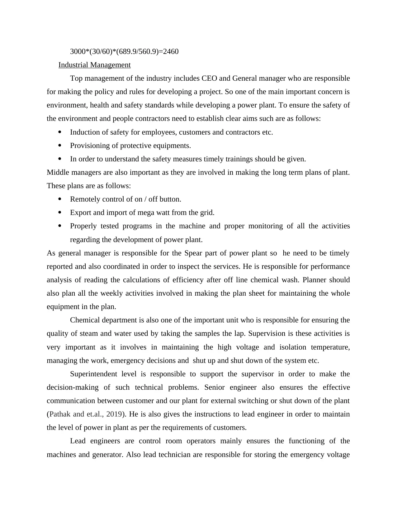
3000*(30/60)*(689.9/560.9)=2460
Industrial Management
Top management of the industry includes CEO and General manager who are responsible
for making the policy and rules for developing a project. So one of the main important concern is
environment, health and safety standards while developing a power plant. To ensure the safety of
the environment and people contractors need to establish clear aims such are as follows:
Induction of safety for employees, customers and contractors etc.
Provisioning of protective equipments.
In order to understand the safety measures timely trainings should be given.
Middle managers are also important as they are involved in making the long term plans of plant.
These plans are as follows:
Remotely control of on / off button.
Export and import of mega watt from the grid.
Properly tested programs in the machine and proper monitoring of all the activities
regarding the development of power plant.
As general manager is responsible for the Spear part of power plant so he need to be timely
reported and also coordinated in order to inspect the services. He is responsible for performance
analysis of reading the calculations of efficiency after off line chemical wash. Planner should
also plan all the weekly activities involved in making the plan sheet for maintaining the whole
equipment in the plan.
Chemical department is also one of the important unit who is responsible for ensuring the
quality of steam and water used by taking the samples the lap. Supervision is these activities is
very important as it involves in maintaining the high voltage and isolation temperature,
managing the work, emergency decisions and shut up and shut down of the system etc.
Superintendent level is responsible to support the supervisor in order to make the
decision-making of such technical problems. Senior engineer also ensures the effective
communication between customer and our plant for external switching or shut down of the plant
(Pathak and et.al., 2019). He is also gives the instructions to lead engineer in order to maintain
the level of power in plant as per the requirements of customers.
Lead engineers are control room operators mainly ensures the functioning of the
machines and generator. Also lead technician are responsible for storing the emergency voltage

equipments as it helps in passing the steam and water. So temperature of steam and water is
proper checked by chemical department.
proper checked by chemical department.
Paraphrase This Document
Need a fresh take? Get an instant paraphrase of this document with our AI Paraphraser
CHAPTER 5 CONCLUSION
According to the suspected issues in power plant, this project help in resolving the
tripping issues involved in manpower and WBH. It has also concluded disturbance in operations
of Gas turbines that impacts on environment. It has also helped in reduced cost of the bathing
heaters in which operations can also be managed by natural gas and LP steam from HRSG
(Costa, Diniz, and Kazmerski, 2016). It has also helped in performing various effective
operations that derives the tripping of water bathing heater. Also it has provided various
components that helped in working of the existing system availability in case when HRSG will
be not available to start gas turbine. In this project, actual cost of the power plant was high but
the modifications and techniques available in this study made it in a limited budget. Main cost of
the WBH maintenance was around $23000 after the modifications it costs around $10000.
This project has also estimated the main cost along with the calculation of last 9 years
cost of maintaining WBH. This study has also provided simplified operations to maintain
required gas temperature in order to operate the GT. It has also helped in making a clear
understanding about the Safety measures to control the risk of power plant as its main operations
includes the flammable substances.
1 out of 38
Your All-in-One AI-Powered Toolkit for Academic Success.
+13062052269
info@desklib.com
Available 24*7 on WhatsApp / Email
![[object Object]](/_next/static/media/star-bottom.7253800d.svg)
Unlock your academic potential
© 2024 | Zucol Services PVT LTD | All rights reserved.