Analysis Report: Soil Nail Performance using Plaxis 2D Simulation
VerifiedAdded on 2023/06/10
|13
|2810
|371
Report
AI Summary
This report presents a detailed analysis of soil nail structures using the finite element analysis (FEA) method and Plaxis 2D software. The study focuses on a soil nail design with two nails to enhance soil stability, simulating the design and analyzing load distribution, forces, and moments. The simulation calculates deformation, stress, and bending moments, with results presented through graphs. The report includes an overview of soil nails, their importance, advantages, and disadvantages. It covers the design process, including initial setup, preprocessing, calculation, and post-processing stages. The analysis involves creating a 2D model, assigning material properties, meshing, and performing calculations to generate results, including deformed shapes, total displacements, stress distributions, and effective stresses. The report also discusses the objectives, PLAXIS modeling techniques, and design considerations. The findings offer valuable insights into soil nail behavior under various loading conditions, making it a beneficial resource for civil engineering students.
EXECUTIVE SUMMARY
In this report the soil nail and its performance characteristics are analysed using the
FEA method. Plaxis was the FEA software tool used in the analysis. The designed soil nail
has two nails attached in the walls to improve the soil stability. Using the Plaxis FEA analysis
tool the design was developed as well as simulated. This simulation part the actual load,
forces, and moments involved in the design was assigned. The deformation, Stress, resultant
bending moments for the applied load was calculated by the simulation process. And also the
various graphs for the different results are plotted using the plaxis. This report also contains
the different simulated results for the given constraints. In this analysis also the detailed
overview about the soil nails as well as its importance was described. And the merits as well
as demerits of the soil nails are also explained in this report.
pg. 1
Paraphrase This Document
Need a fresh take? Get an instant paraphrase of this document with our AI Paraphraser
CONTENTS
EXECUTIVE SUMMARY...................................................................................................................1
LIST OF FIGURES...............................................................................................................................3
1. OVERVIEW..................................................................................................................................4
2. OBJECTIVES................................................................................................................................5
3. PLAXIS MODELING...................................................................................................................5
4. DESIGN PROCESS......................................................................................................................5
5. CALCULATIONS.........................................................................................................................8
6. RESULTS SUMMARY................................................................................................................9
7. RESULT DISCUSSION..............................................................................................................12
8. CONCLUSION...........................................................................................................................13
REFERENCE......................................................................................................................................14
LIST OF FIGURES
Figure 1 Initial setup..............................................................................................................................6
Figure 2 Design development................................................................................................................7
Figure 3 Material property assigning.....................................................................................................7
Figure 4 Meshing...................................................................................................................................8
Figure 5 Calcuations..............................................................................................................................9
Figure 6 Deformed Shape....................................................................................................................10
Figure 7 Total displacements...............................................................................................................10
Figure 8 Displacement diagram...........................................................................................................10
Figure 9 Effective stress......................................................................................................................11
Figure 10 Effective mean stress..........................................................................................................11
Figure 11 Relative shear stress............................................................................................................11
Figure 12 Deviatoric stress..................................................................................................................12
Figure 13 Result graphs.......................................................................................................................13
Figure 14 Results.................................................................................................................................13
pg. 2
1. OVERVIEW
In this we are going to examine about soil nailing. That is used to maintain vertical
slops using steel bars in open manner from up to down in the process of digging. This technic
is famous for entrepreneur as it is essential for cash making in different ground. This method
is more popular in Europe for past 45yrs and in 25yrs US have seen lot of interest in this
nailing process and the same process is followed by Egypt in various projects like city stars,
toshka pump station and for maintaining slopes and canals has largely assumed in last few
years. This gives a strategy of soil nailing for past years. There are several stages in this
testing .They are described in the below context. First stage was the soil enhancing process.
Easy to enhance soil nailing in city stars task with 3 various nails .there is a difference
between the results of horizontal displacements and final stage of constructed with countable
elements models gained from the data. That leads to find the best nail design that enhance
each walls. Second stage was the analysis stage. For research of soil nailing the best nail is
taken from the last stage. According to the parametric study that defines the design
constraints of various nails about nail length to wall height ratio, nail spacing, wall
inclination, nail inclination and soil properties on the global factor of precautions in the
plaxis. Third and Last stage was the checking stage. As per the study in the prior stags user to
invent factors of safety and horizontal displacement in the top of the soil nailed wall stage of
plaxis .And this selected for the global factor in the friction angle to avoid the problem. It is
also rectify the deformation modulus or wall high values are the various values to develop the
design charts. To check and examine the usage of design charts they are another 2 cases.
Application of Soil Nails
Soil nailing technique was mainly used to excavating process carried out on the soil.
This process improves the stability of the soil by reduce the deformations caused by the
applied loads as well as forces. During the bridge construction activities this technique was
used as a reinforcement. That also brings the better strength to the soil. Mostly this technique
was used in the structural developments on the low strength soils. It will also implemented
for the road construction works. It is developed as a permanent structures or the temporary
one based on the requirement. This technique also reduces the excavation of the soil. It also
improves the hassle free transportation capabilities in the extremely remote areas.
pg. 3
⊘ This is a preview!⊘
Do you want full access?
Subscribe today to unlock all pages.

Trusted by 1+ million students worldwide
2. OBJECTIVES
In this project the design and analysis of the soil nail structure using the “PLAXIS”
FEA tool. For this analysis we need to develop the 2d model of the structure in the plaxix
tool. After developing the 2d outline design of the structure we need to assign material
properties to the various elements in the system. Then the mesh was created for the
mathematical analysis of the system. After developing the mesh, we need to proceed
calculations. For that process we need to give the different parameters like load, density etc.
After giving all the required data we need to proceed the calculation. Then we need to
generate the different outputs for the design.
3. PLAXIS MODELING
Soil nailing is known as the approach in the kind of top down method. In that soil
nailing the slope is analyzed through the continuous method to create the work and in that
works the safety is essential one and also it need to be stable. And the soil nailing method is
used to cut the slopes and it take in this to the next level while the soil level installed. Due to
the mistake while cutting the slopes the soil nails is not similar.
And by the consideration of slopes the soil nails can be used to describe the heights
and cutting stage of the slope. When cutting the slop for the constant time the site is needed.
And in this the works will not more time for the completion and it take nearly 3 and both take
in one time. For the constraints the designer must be alert with the instructions. And the each
point of stage in the process should be included in construction drawings and work
regulations.
This design and simulation works was completed using the plaxis software. The design
consists of the two soil nails on its right side. These nails are considered as the cylindrical
shape. These nails are made by the material haves higher tensile strength. The nails was used
to strengthen the soil to improve the stability of the wall.
4. DESIGN PROCESS
The design process for this plaxis analysis was quite similar to all the FEA tools. This
contains four design phases (Plaxis.com, 2018). They are discussed below in this report. Here
the design process of the soil nail analysis was listed below,
Initial setup
Pre processing
Calculation
pg. 4
Paraphrase This Document
Need a fresh take? Get an instant paraphrase of this document with our AI Paraphraser
Post processing
Initial setup
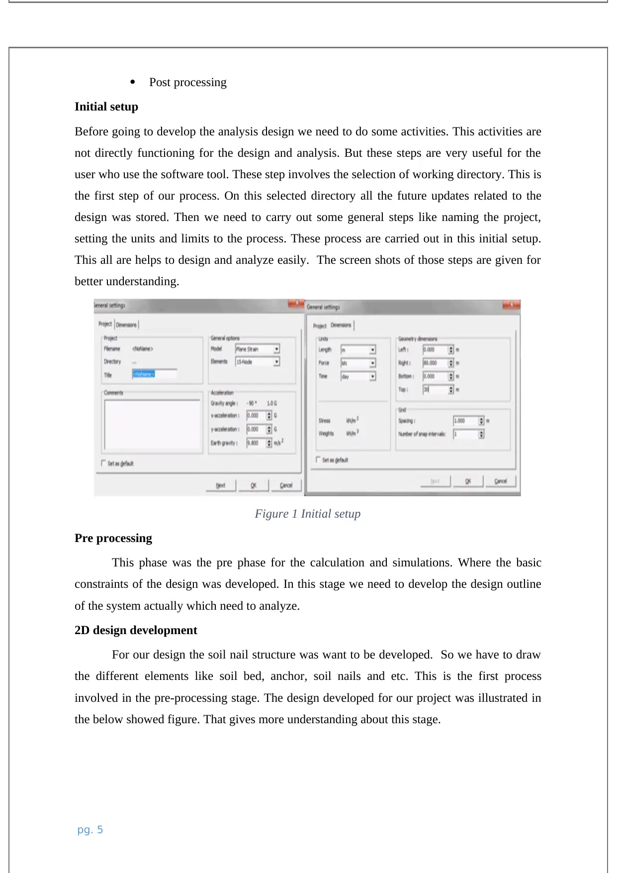
Before going to develop the analysis design we need to do some activities. This activities are
not directly functioning for the design and analysis. But these steps are very useful for the
user who use the software tool. These step involves the selection of working directory. This is
the first step of our process. On this selected directory all the future updates related to the
design was stored. Then we need to carry out some general steps like naming the project,
setting the units and limits to the process. These process are carried out in this initial setup.
This all are helps to design and analyze easily. The screen shots of those steps are given for
better understanding.
Figure 1 Initial setup
Pre processing
This phase was the pre phase for the calculation and simulations. Where the basic
constraints of the design was developed. In this stage we need to develop the design outline
of the system actually which need to analyze.
2D design development
For our design the soil nail structure was want to be developed. So we have to draw
the different elements like soil bed, anchor, soil nails and etc. This is the first process
involved in the pre-processing stage. The design developed for our project was illustrated in
the below showed figure. That gives more understanding about this stage.
pg. 5
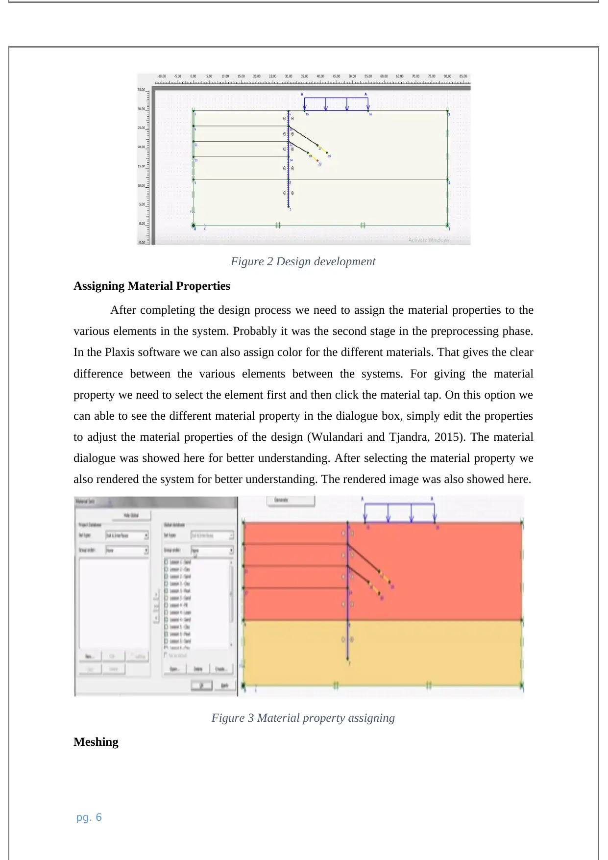
Figure 2 Design development
Assigning Material Properties
After completing the design process we need to assign the material properties to the
various elements in the system. Probably it was the second stage in the preprocessing phase.
In the Plaxis software we can also assign color for the different materials. That gives the clear
difference between the various elements between the systems. For giving the material
property we need to select the element first and then click the material tap. On this option we
can able to see the different material property in the dialogue box, simply edit the properties
to adjust the material properties of the design (Wulandari and Tjandra, 2015). The material
dialogue was showed here for better understanding. After selecting the material property we
also rendered the system for better understanding. The rendered image was also showed here.
Figure 3 Material property assigning
Meshing
pg. 6
⊘ This is a preview!⊘
Do you want full access?
Subscribe today to unlock all pages.

Trusted by 1+ million students worldwide
It is the final stage in the preprocessing stage. In this process we need to discretize the
system. This step was carried out to make the accurate calculations. This process was the
important process in any FEA software. In this software we can simply generate the mesh by
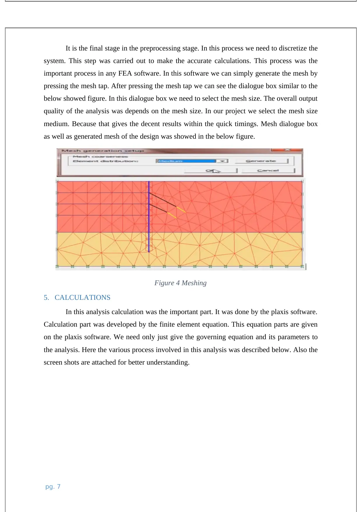
pressing the mesh tap. After pressing the mesh tap we can see the dialogue box similar to the
below showed figure. In this dialogue box we need to select the mesh size. The overall output
quality of the analysis was depends on the mesh size. In our project we select the mesh size
medium. Because that gives the decent results within the quick timings. Mesh dialogue box
as well as generated mesh of the design was showed in the below figure.
Figure 4 Meshing
5. CALCULATIONS
In this analysis calculation was the important part. It was done by the plaxis software.
Calculation part was developed by the finite element equation. This equation parts are given
on the plaxis software. We need only just give the governing equation and its parameters to
the analysis. Here the various process involved in this analysis was described below. Also the
screen shots are attached for better understanding.
pg. 7
Paraphrase This Document
Need a fresh take? Get an instant paraphrase of this document with our AI Paraphraser
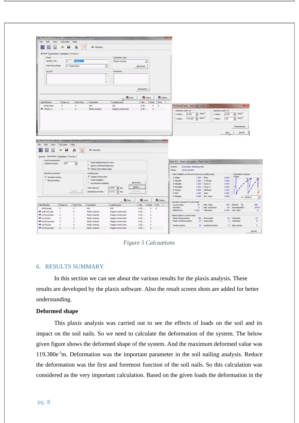
Figure 5 Calcuations
6. RESULTS SUMMARY
In this section we can see about the various results for the plaxis analysis. These
results are developed by the plaxis software. Also the result screen shots are added for better
understanding.
Deformed shape
This plaxis analysis was carried out to see the effects of loads on the soil and its
impact on the soil nails. So we need to calculate the deformation of the system. The below
given figure shows the deformed shape of the system. And the maximum deformed value was
119.380e-3m. Deformation was the important parameter in the soil nailing analysis. Reduce
the deformation was the first and foremost function of the soil nails. So this calculation was
considered as the very important calculation. Based on the given loads the deformation in the
pg. 8
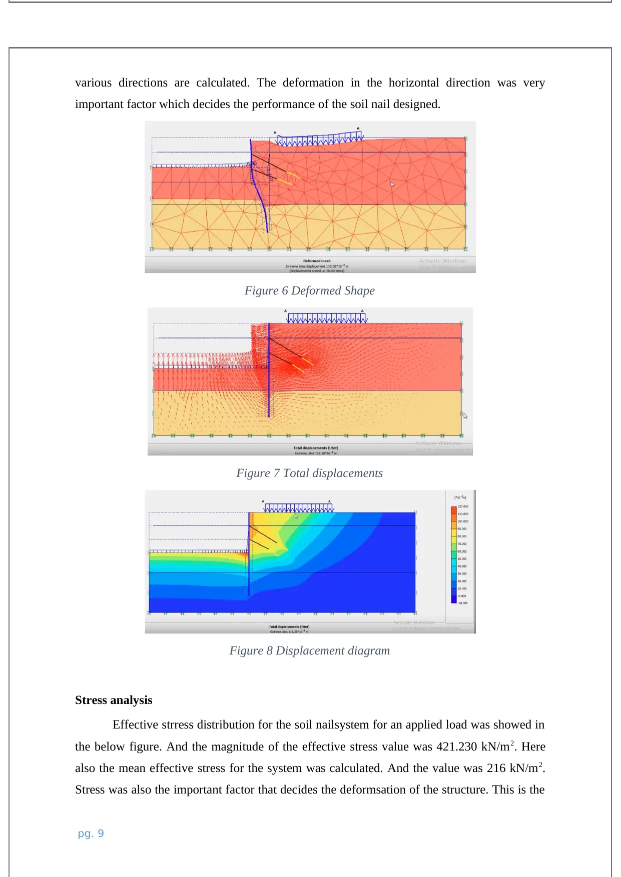
various directions are calculated. The deformation in the horizontal direction was very
important factor which decides the performance of the soil nail designed.
Figure 6 Deformed Shape
Figure 7 Total displacements
Figure 8 Displacement diagram
Stress analysis
Effective strress distribution for the soil nailsystem for an applied load was showed in
the below figure. And the magnitude of the effective stress value was 421.230 kN/m2. Here
also the mean effective stress for the system was calculated. And the value was 216 kN/m2.
Stress was also the important factor that decides the deformsation of the structure. This is the
pg. 9
⊘ This is a preview!⊘
Do you want full access?
Subscribe today to unlock all pages.

Trusted by 1+ million students worldwide
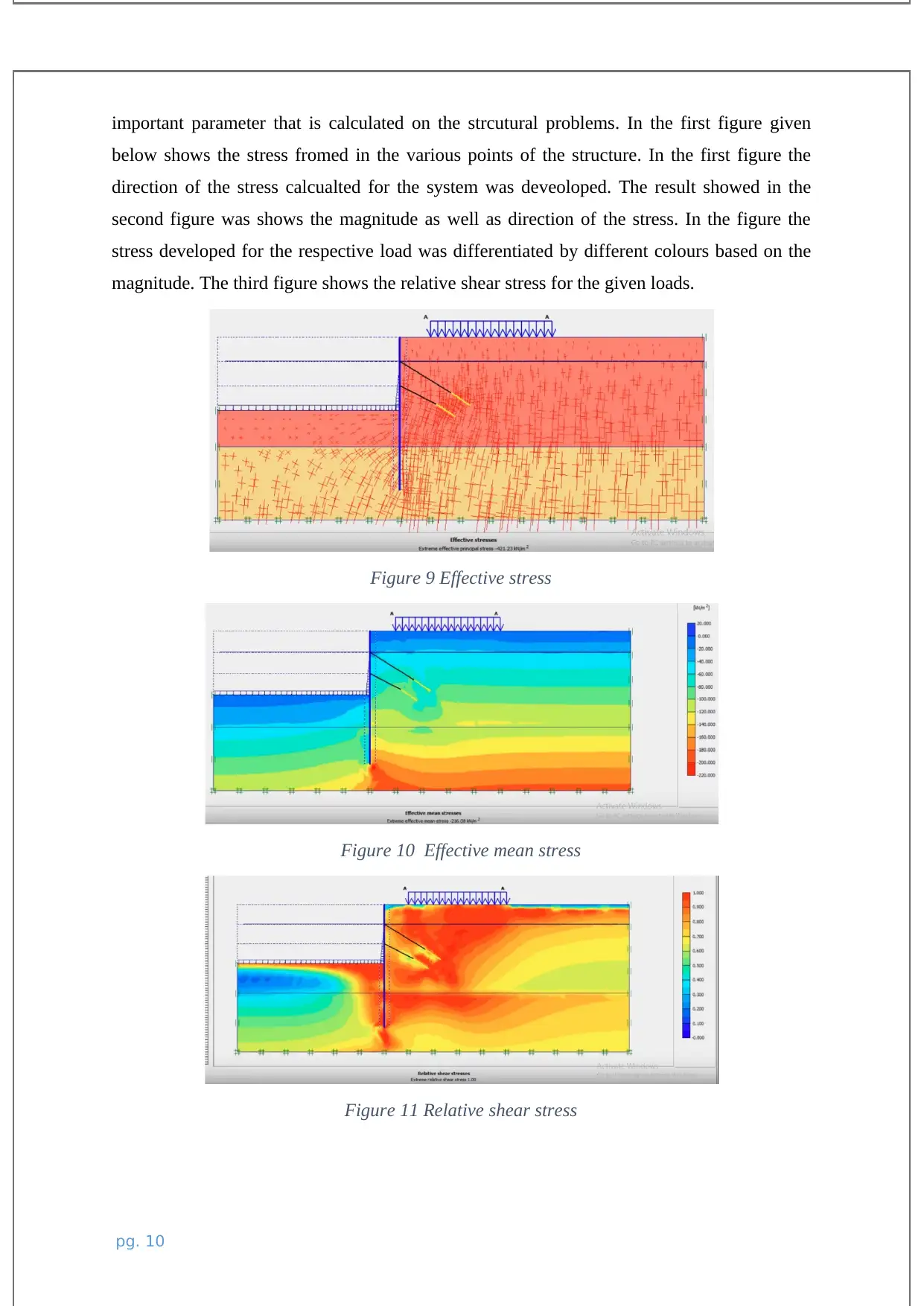
important parameter that is calculated on the strcutural problems. In the first figure given
below shows the stress fromed in the various points of the structure. In the first figure the
direction of the stress calcualted for the system was deveoloped. The result showed in the
second figure was shows the magnitude as well as direction of the stress. In the figure the
stress developed for the respective load was differentiated by different colours based on the
magnitude. The third figure shows the relative shear stress for the given loads.
Figure 9 Effective stress
Figure 10 Effective mean stress
Figure 11 Relative shear stress
pg. 10
Paraphrase This Document
Need a fresh take? Get an instant paraphrase of this document with our AI Paraphraser
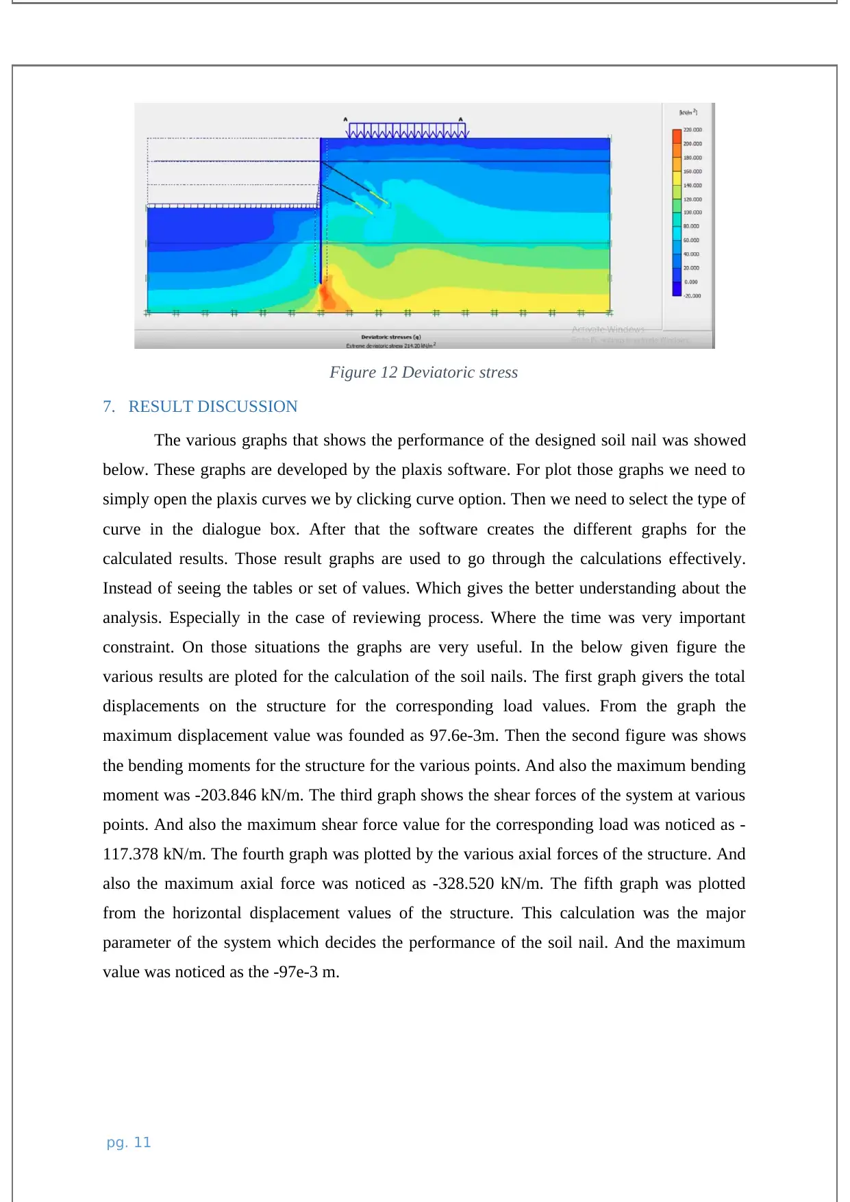
Figure 12 Deviatoric stress
7. RESULT DISCUSSION
The various graphs that shows the performance of the designed soil nail was showed
below. These graphs are developed by the plaxis software. For plot those graphs we need to
simply open the plaxis curves we by clicking curve option. Then we need to select the type of
curve in the dialogue box. After that the software creates the different graphs for the
calculated results. Those result graphs are used to go through the calculations effectively.
Instead of seeing the tables or set of values. Which gives the better understanding about the
analysis. Especially in the case of reviewing process. Where the time was very important
constraint. On those situations the graphs are very useful. In the below given figure the
various results are ploted for the calculation of the soil nails. The first graph givers the total
displacements on the structure for the corresponding load values. From the graph the
maximum displacement value was founded as 97.6e-3m. Then the second figure was shows
the bending moments for the structure for the various points. And also the maximum bending
moment was -203.846 kN/m. The third graph shows the shear forces of the system at various
points. And also the maximum shear force value for the corresponding load was noticed as -
117.378 kN/m. The fourth graph was plotted by the various axial forces of the structure. And
also the maximum axial force was noticed as -328.520 kN/m. The fifth graph was plotted
from the horizontal displacement values of the structure. This calculation was the major
parameter of the system which decides the performance of the soil nail. And the maximum
value was noticed as the -97e-3 m.
pg. 11
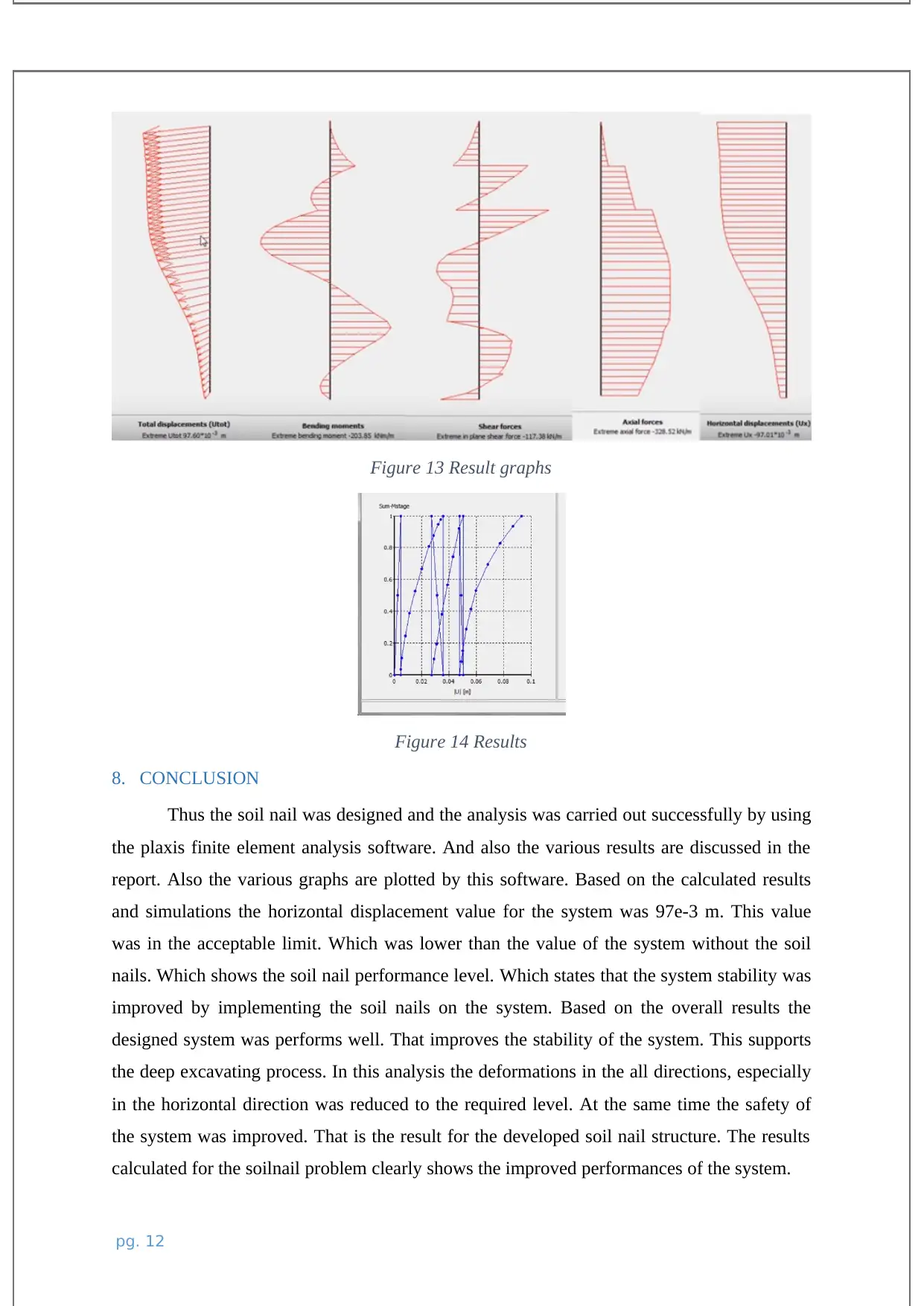
Figure 13 Result graphs
Figure 14 Results
8. CONCLUSION
Thus the soil nail was designed and the analysis was carried out successfully by using
the plaxis finite element analysis software. And also the various results are discussed in the
report. Also the various graphs are plotted by this software. Based on the calculated results
and simulations the horizontal displacement value for the system was 97e-3 m. This value
was in the acceptable limit. Which was lower than the value of the system without the soil
nails. Which shows the soil nail performance level. Which states that the system stability was
improved by implementing the soil nails on the system. Based on the overall results the
designed system was performs well. That improves the stability of the system. This supports
the deep excavating process. In this analysis the deformations in the all directions, especially
in the horizontal direction was reduced to the required level. At the same time the safety of
the system was improved. That is the result for the developed soil nail structure. The results
calculated for the soilnail problem clearly shows the improved performances of the system.
pg. 12
⊘ This is a preview!⊘
Do you want full access?
Subscribe today to unlock all pages.

Trusted by 1+ million students worldwide
1 out of 13
Related Documents
Your All-in-One AI-Powered Toolkit for Academic Success.
+13062052269
info@desklib.com
Available 24*7 on WhatsApp / Email
![[object Object]](/_next/static/media/star-bottom.7253800d.svg)
Unlock your academic potential
Copyright © 2020–2025 A2Z Services. All Rights Reserved. Developed and managed by ZUCOL.


