Structural Optimization of Solar Collector Plate
VerifiedAdded on 2023/06/10
|24
|2920
|175
AI Summary
The article discusses the design and optimization of a solar collector plate made up of photovoltaic cells. It covers the mathematical formulation, finite element analysis, and optimization algorithm used for the project. The article also provides insights into the results obtained from ANSYS software. The objective of the project is to minimize the cost of the collector plate while ensuring that the surface area of the plate is at least 5 square meters for domestic purposes. The article also includes the subject, course code, and university name.
Contribute Materials
Your contribution can guide someone’s learning journey. Share your
documents today.

Structural Optimization of Solar Collector Plate
Computer-aided Mechanical Design – 49325
Prepared by:
NAME STUDENT ID
Swapan Bhatt 99159333
Jaimin Patel 12486318
Manthan Rawal 12441630
Munjal Pandya 12424026
Saranjay Akatra 12523825
Amal Mathew 12660546
Shail Jani 12181246
OCTOBER 26, 2016
UNIVERSITY OF TECHNOLOGY, sYDNEY
Computer-aided Mechanical Design – 49325
Prepared by:
NAME STUDENT ID
Swapan Bhatt 99159333
Jaimin Patel 12486318
Manthan Rawal 12441630
Munjal Pandya 12424026
Saranjay Akatra 12523825
Amal Mathew 12660546
Shail Jani 12181246
OCTOBER 26, 2016
UNIVERSITY OF TECHNOLOGY, sYDNEY
Secure Best Marks with AI Grader
Need help grading? Try our AI Grader for instant feedback on your assignments.
1 PROJECT DIFINITION
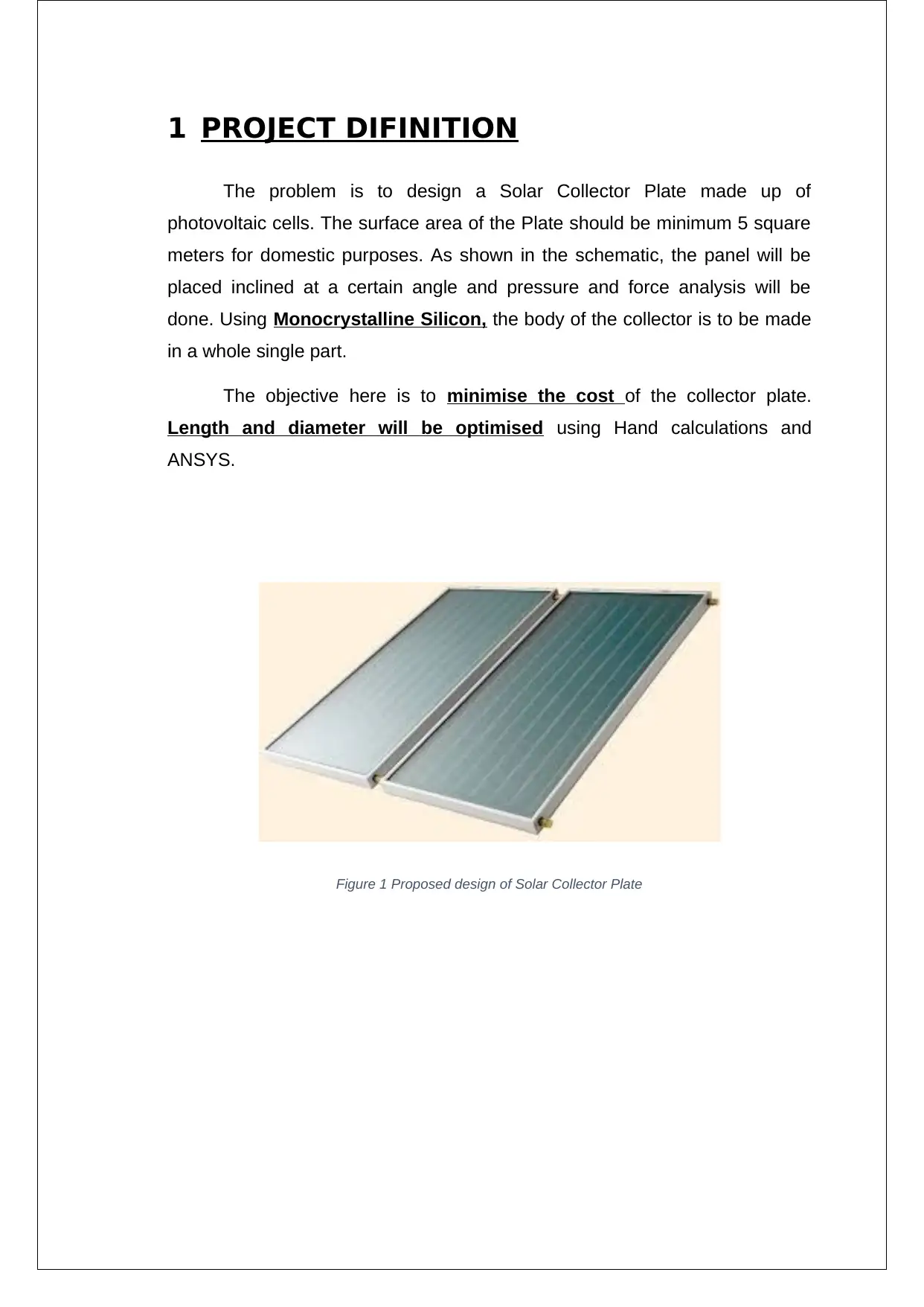
The problem is to design a Solar Collector Plate made up of
photovoltaic cells. The surface area of the Plate should be minimum 5 square
meters for domestic purposes. As shown in the schematic, the panel will be
placed inclined at a certain angle and pressure and force analysis will be
done. Using Monocrystalline Silicon, the body of the collector is to be made
in a whole single part.
The objective here is to minimise the cost of the collector plate.
Length and diameter will be optimised using Hand calculations and
ANSYS.
Figure 1 Proposed design of Solar Collector Plate
2 OPTIMIZATION ALGORITHM
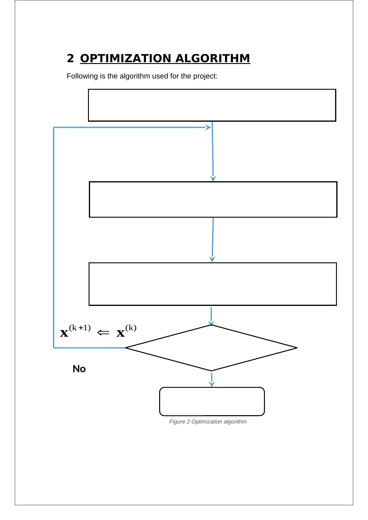
Following is the algorithm used for the project:
No
(k 1) (k) x x
Optimal Design
Step 1: Mathematical Formulation
(Design variables, Objective, Constraints)
Step 2: Finite Element Analysis
[K]{U}={F}
Step 4: Optimization Algorithm
(Based on the design sensitivities, to update of
the design variables)
Convergence
?
Figure 2 Optimization algorithm
3 MATHEMATICAL FORMULATION
3.1ASSUMPTIONS
A general solar panel dimensions is taken into consideration.
Optimization and Analysis will be conducting for front, back and side
faces of the solar panel.
Wind speeds around 90 and 120 km/hr is taken into consideration
against the solar panel.
3.2MATHEMATICAL MODEL
The design of solar panel will be based on the area and cost. The outer
body of the panel is subjected to wind pressure.
From the objective function that was formed, the constraints were
created by working on ANSYS to get an optimal solution. From the optimal
solution, we worked on Solidworks to model the solar panel. Once the model
was obtained from Solidworks, we worked on ANSYS to get the optimum
solution. However, we had to remodel the constraints and our design
variables in order to satisfy our objective function. The final mathematical
model shown above is the optimised one.
For the solar panel the following variables were considered:
Length of the solar panel ‘ l’
Width of the solar panel ‘w’
The Objective Function is :
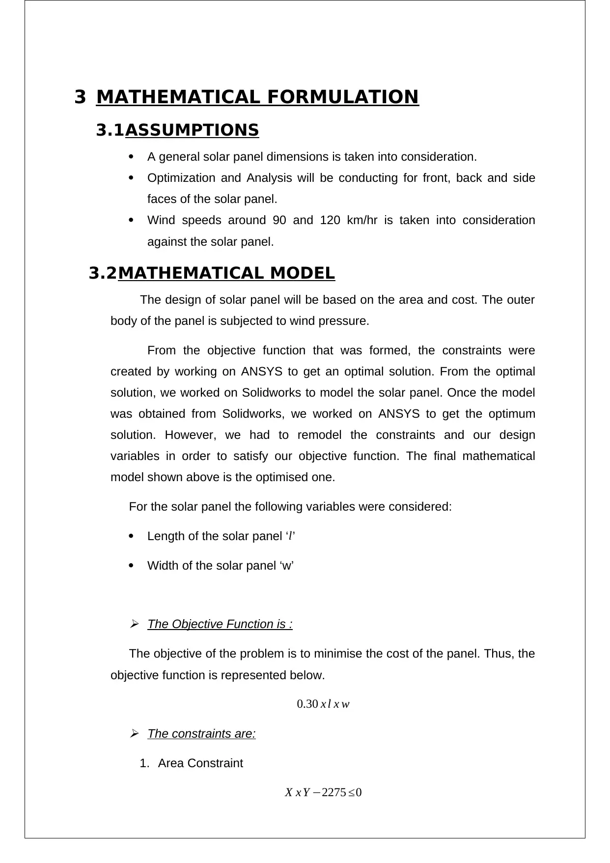
The objective of the problem is to minimise the cost of the panel. Thus, the
objective function is represented below.
0.30 x l x w The constraints are:
1. Area Constraint
X x Y −2275 ≤0
3.1ASSUMPTIONS
A general solar panel dimensions is taken into consideration.
Optimization and Analysis will be conducting for front, back and side
faces of the solar panel.
Wind speeds around 90 and 120 km/hr is taken into consideration
against the solar panel.
3.2MATHEMATICAL MODEL
The design of solar panel will be based on the area and cost. The outer
body of the panel is subjected to wind pressure.
From the objective function that was formed, the constraints were
created by working on ANSYS to get an optimal solution. From the optimal
solution, we worked on Solidworks to model the solar panel. Once the model
was obtained from Solidworks, we worked on ANSYS to get the optimum
solution. However, we had to remodel the constraints and our design
variables in order to satisfy our objective function. The final mathematical
model shown above is the optimised one.
For the solar panel the following variables were considered:
Length of the solar panel ‘ l’
Width of the solar panel ‘w’
The Objective Function is :
The objective of the problem is to minimise the cost of the panel. Thus, the
objective function is represented below.
0.30 x l x w The constraints are:
1. Area Constraint
X x Y −2275 ≤0
Secure Best Marks with AI Grader
Need help grading? Try our AI Grader for instant feedback on your assignments.
2. Solar panel design parameters
Upper and lower boundaries
o 50 ≤ l≤ 100
o 35 ≤ w ≤ 80
Note that values are in inches and the optimisation solutions have been
calculated by hand and attached with the report.
The value of optimised length is 50 inches and width is 35 inches.
The overall cost is 0.30 x Area = AUD 525
4 FINITE ELEMENT PROCEDURES AND
ANALYSIS
To obtain proper analysis of the solar panel, ANSYS software was used.
The following tables are the outputs of the software.
4.1ENGINEERING DATA
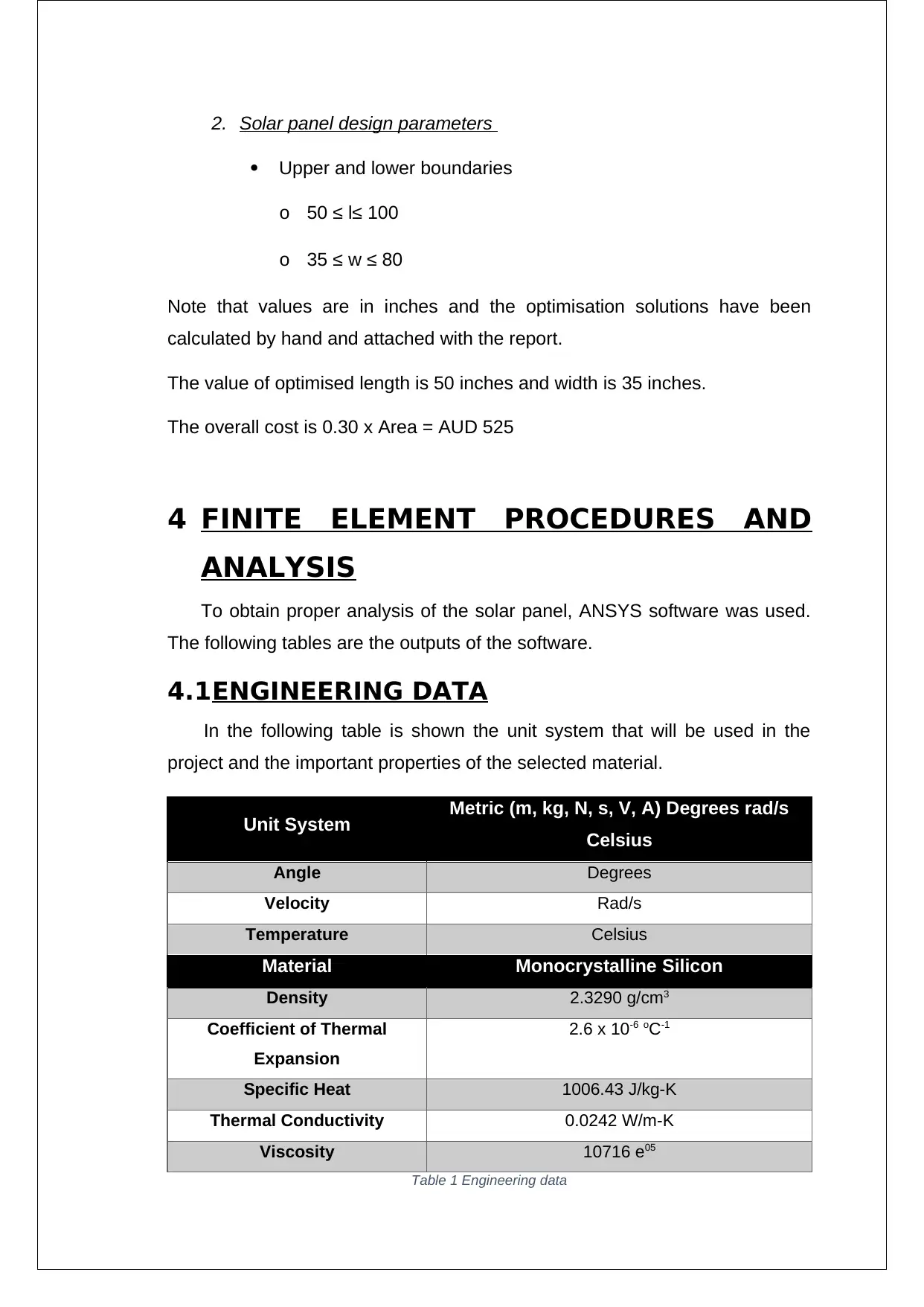
In the following table is shown the unit system that will be used in the
project and the important properties of the selected material.
Unit System Metric (m, kg, N, s, V, A) Degrees rad/s
Celsius
Angle Degrees
Velocity Rad/s
Temperature Celsius
Material Monocrystalline Silicon
Density 2.3290 g/cm3
Coefficient of Thermal
Expansion
2.6 x 10⁻⁶ oC-1
Specific Heat 1006.43 J/kg-K
Thermal Conductivity 0.0242 W/m-K
Viscosity 10716 e05
Table 1 Engineering data
Upper and lower boundaries
o 50 ≤ l≤ 100
o 35 ≤ w ≤ 80
Note that values are in inches and the optimisation solutions have been
calculated by hand and attached with the report.
The value of optimised length is 50 inches and width is 35 inches.
The overall cost is 0.30 x Area = AUD 525
4 FINITE ELEMENT PROCEDURES AND
ANALYSIS
To obtain proper analysis of the solar panel, ANSYS software was used.
The following tables are the outputs of the software.
4.1ENGINEERING DATA
In the following table is shown the unit system that will be used in the
project and the important properties of the selected material.
Unit System Metric (m, kg, N, s, V, A) Degrees rad/s
Celsius
Angle Degrees
Velocity Rad/s
Temperature Celsius
Material Monocrystalline Silicon
Density 2.3290 g/cm3
Coefficient of Thermal
Expansion
2.6 x 10⁻⁶ oC-1
Specific Heat 1006.43 J/kg-K
Thermal Conductivity 0.0242 W/m-K
Viscosity 10716 e05
Table 1 Engineering data
4.2GEOMETRY
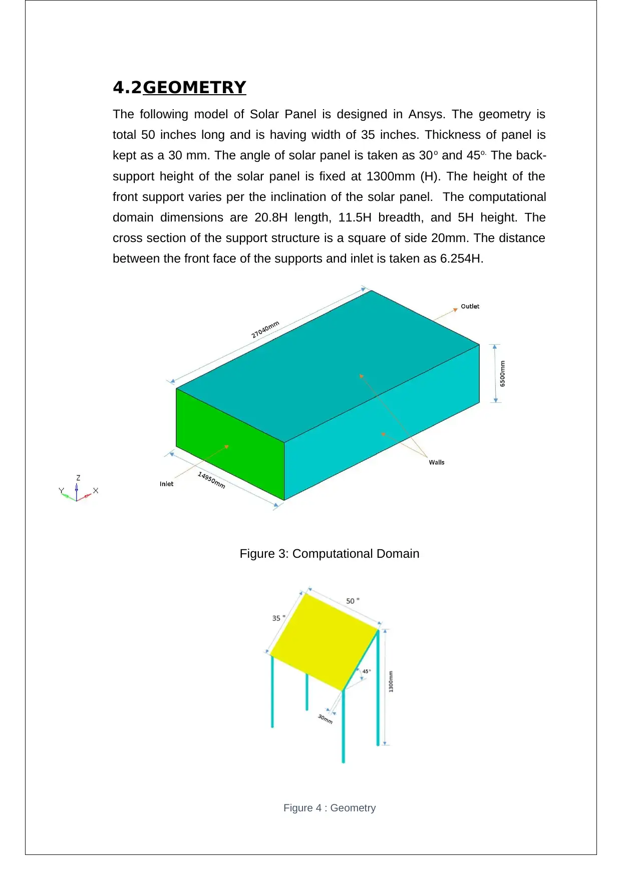
The following model of Solar Panel is designed in Ansys. The geometry is
total 50 inches long and is having width of 35 inches. Thickness of panel is
kept as a 30 mm. The angle of solar panel is taken as 30o and 45o. The back-
support height of the solar panel is fixed at 1300mm (H). The height of the
front support varies per the inclination of the solar panel. The computational
domain dimensions are 20.8H length, 11.5H breadth, and 5H height. The
cross section of the support structure is a square of side 20mm. The distance
between the front face of the supports and inlet is taken as 6.254H.
Figure 3: Computational Domain
Figure 4 : Geometry
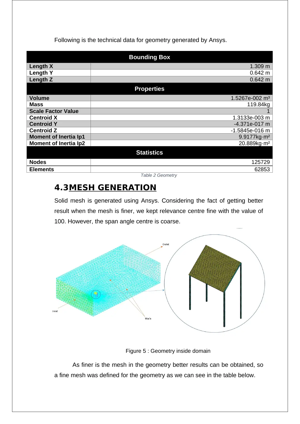
Following is the technical data for geometry generated by Ansys.
Bounding Box
Length X 1.309 m
Length Y 0.642 m
Length Z 0.642 m
Properties
Volume 1.5267e-002 m³
Mass 119.84kg
Scale Factor Value 1
Centroid X 1.3133e-003 m
Centroid Y -4.371e-017 m
Centroid Z -1.5845e-016 m
Moment of Inertia Ip1 9.9177kg·m²
Moment of Inertia Ip2 20.889kg·m²
Statistics
Nodes 125729
Elements 62853
Table 2 Geometry
4.3MESH GENERATION
Solid mesh is generated using Ansys. Considering the fact of getting better
result when the mesh is finer, we kept relevance centre fine with the value of
100. However, the span angle centre is coarse.
Figure 5 : Geometry inside domain
As finer is the mesh in the geometry better results can be obtained, so
a fine mesh was defined for the geometry as we can see in the table below.
Paraphrase This Document
Need a fresh take? Get an instant paraphrase of this document with our AI Paraphraser
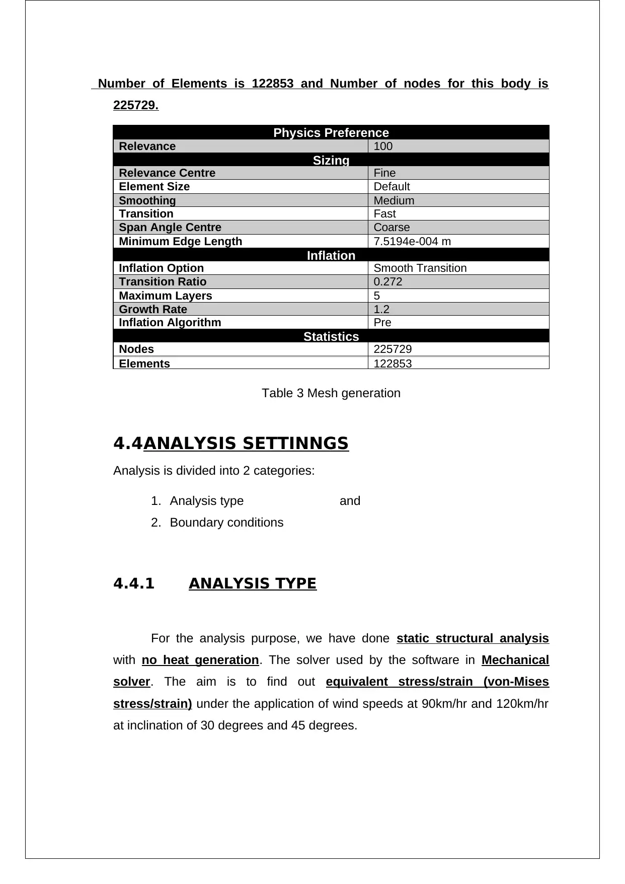
Number of Elements is 122853 and Number of nodes for this body is
225729.
Table 3 Mesh generation
4.4ANALYSIS SETTINNGS
Analysis is divided into 2 categories:
1. Analysis type and
2. Boundary conditions
4.4.1 ANALYSIS TYPE
For the analysis purpose, we have done static structural analysis
with no heat generation. The solver used by the software in Mechanical
solver. The aim is to find out equivalent stress/strain (von-Mises
stress/strain) under the application of wind speeds at 90km/hr and 120km/hr
at inclination of 30 degrees and 45 degrees.
Physics Preference
Relevance 100
Sizing
Relevance Centre Fine
Element Size Default
Smoothing Medium
Transition Fast
Span Angle Centre Coarse
Minimum Edge Length 7.5194e-004 m
Inflation
Inflation Option Smooth Transition
Transition Ratio 0.272
Maximum Layers 5
Growth Rate 1.2
Inflation Algorithm Pre
Statistics
Nodes 225729
Elements 122853
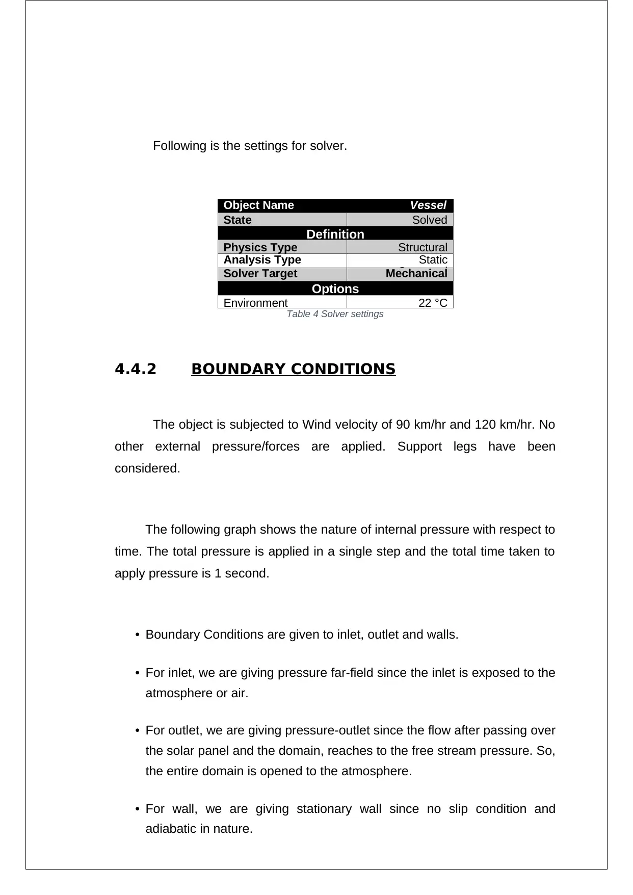
Following is the settings for solver.
Object Name Vessel
State Solved
Definition
Physics Type Structural
Analysis Type Static
StructuralSolver Target Mechanical
APDLOptions
Environment 22 °C
Table 4 Solver settings
4.4.2 BOUNDARY CONDITIONS
The object is subjected to Wind velocity of 90 km/hr and 120 km/hr. No
other external pressure/forces are applied. Support legs have been
considered.
The following graph shows the nature of internal pressure with respect to
time. The total pressure is applied in a single step and the total time taken to
apply pressure is 1 second.
• Boundary Conditions are given to inlet, outlet and walls.
• For inlet, we are giving pressure far-field since the inlet is exposed to the
atmosphere or air.
• For outlet, we are giving pressure-outlet since the flow after passing over
the solar panel and the domain, reaches to the free stream pressure. So,
the entire domain is opened to the atmosphere.
• For wall, we are giving stationary wall since no slip condition and
adiabatic in nature.
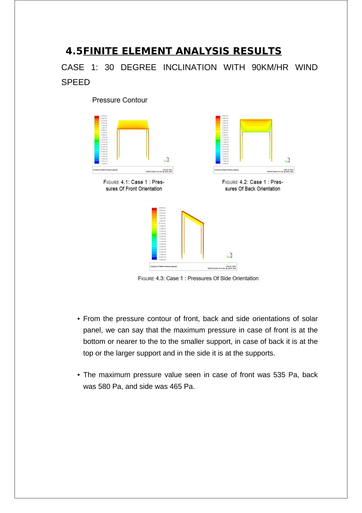
4.5FINITE ELEMENT ANALYSIS RESULTS
CASE 1: 30 DEGREE INCLINATION WITH 90KM/HR WIND
SPEED
• From the pressure contour of front, back and side orientations of solar
panel, we can say that the maximum pressure in case of front is at the
bottom or nearer to the to the smaller support, in case of back it is at the
top or the larger support and in the side it is at the supports.
• The maximum pressure value seen in case of front was 535 Pa, back
was 580 Pa, and side was 465 Pa.
Secure Best Marks with AI Grader
Need help grading? Try our AI Grader for instant feedback on your assignments.
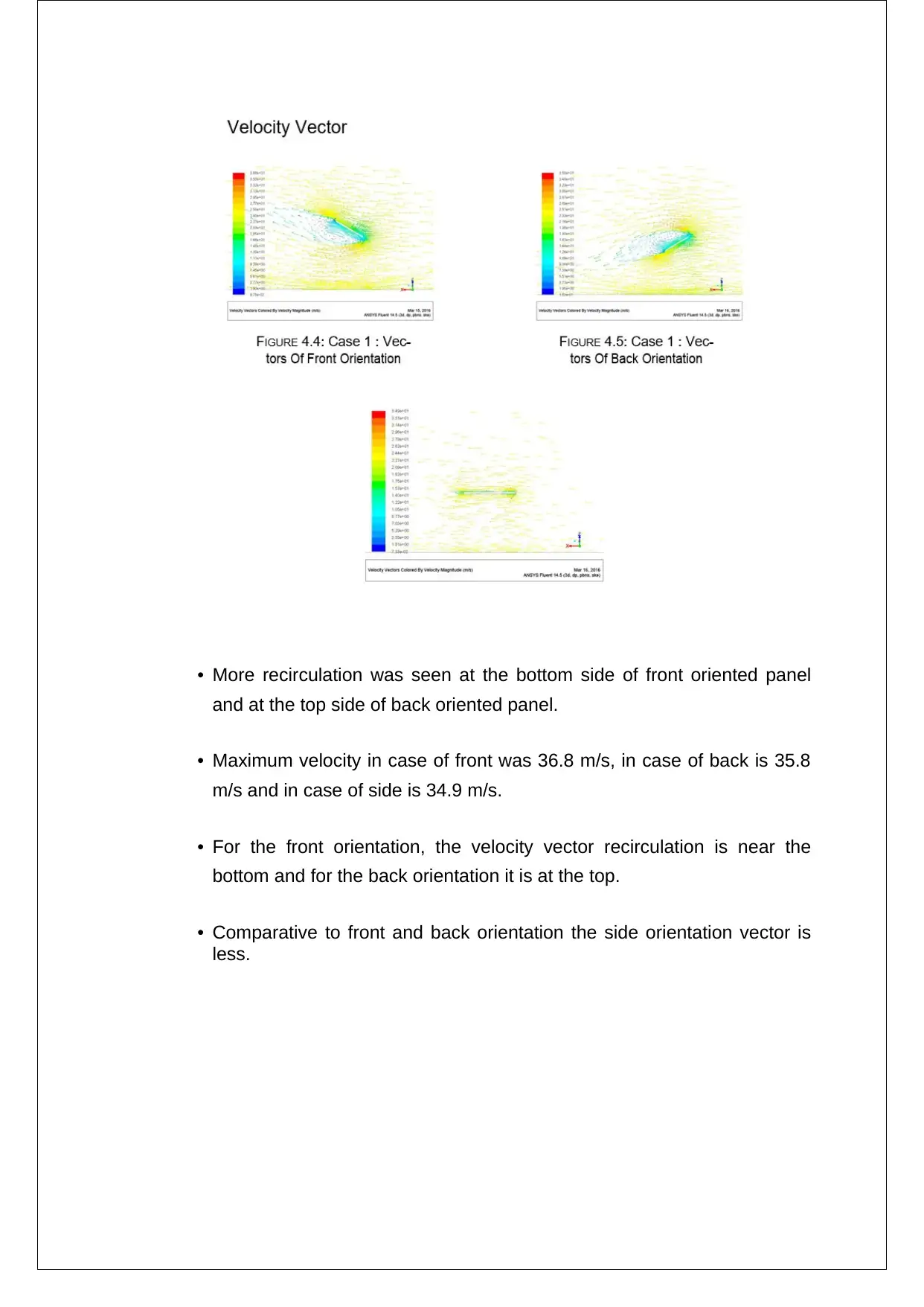
• More recirculation was seen at the bottom side of front oriented panel
and at the top side of back oriented panel.
• Maximum velocity in case of front was 36.8 m/s, in case of back is 35.8
m/s and in case of side is 34.9 m/s.
• For the front orientation, the velocity vector recirculation is near the
bottom and for the back orientation it is at the top.
• Comparative to front and back orientation the side orientation vector is
less.

From the figures, it is evident that there is considerable amount of
recirculation in the front and back orientations, whereas no recirculation in the
side orientation. Recircula-tion indicates a low pressure region. Therefore
lower the pressure, more the recircula-tion.
In case of front oriented solar panel, the recirculation is in the bottom side
which causes a negative lift. The lift force is found to be -69.95 N. In back
oriented solar panel, the recirculation is on the top side, which induces a
positive lift force measured at 150.88 N. Even though there is no recirculation
in case of side orientation, the pressure difference in the top and bottom of the
solar panel causes a positive lift equal to 16.14
COMPUTER-AIDED MECHANICAL DESIGN – 49325
PROJECT: STRUCTURAL OPTIMIZATION OF SOLAR COLLECTOR PLATE
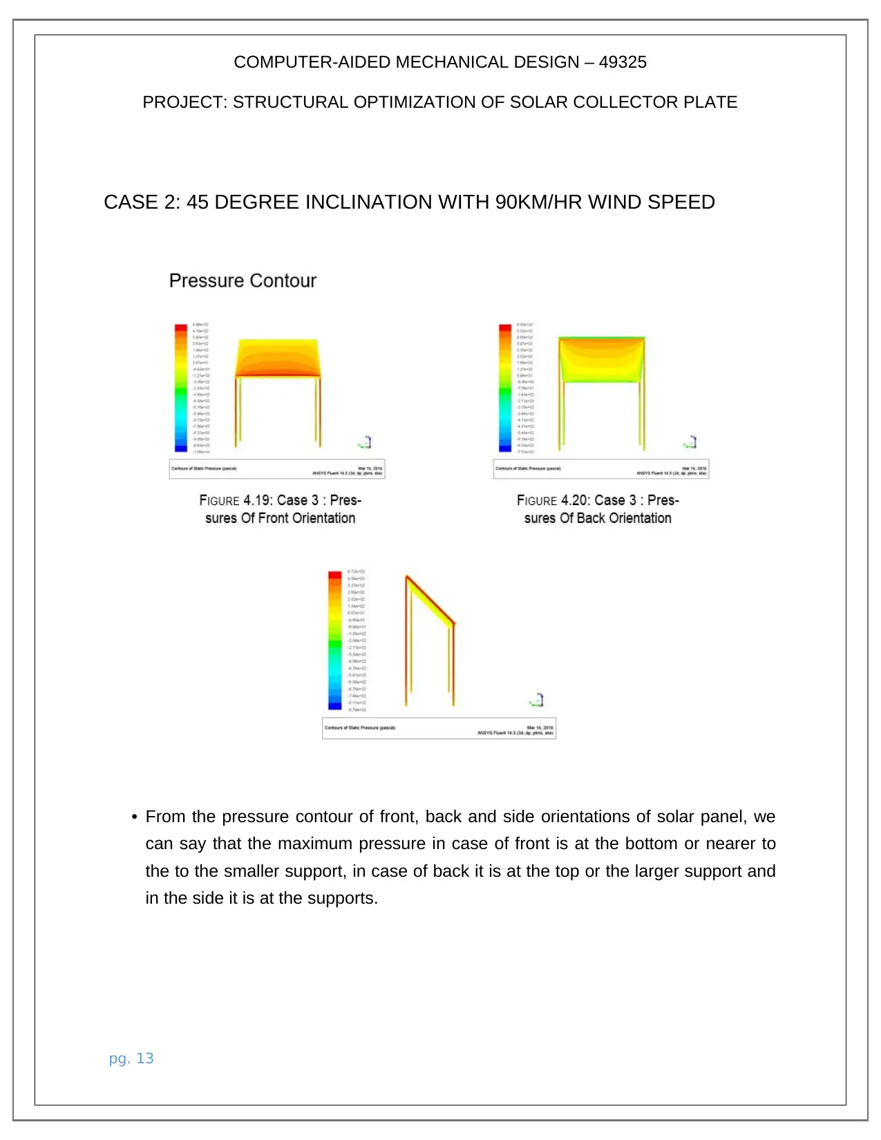
CASE 2: 45 DEGREE INCLINATION WITH 90KM/HR WIND SPEED
• From the pressure contour of front, back and side orientations of solar panel, we
can say that the maximum pressure in case of front is at the bottom or nearer to
the to the smaller support, in case of back it is at the top or the larger support and
in the side it is at the supports.
pg. 13
PROJECT: STRUCTURAL OPTIMIZATION OF SOLAR COLLECTOR PLATE
CASE 2: 45 DEGREE INCLINATION WITH 90KM/HR WIND SPEED
• From the pressure contour of front, back and side orientations of solar panel, we
can say that the maximum pressure in case of front is at the bottom or nearer to
the to the smaller support, in case of back it is at the top or the larger support and
in the side it is at the supports.
pg. 13
Paraphrase This Document
Need a fresh take? Get an instant paraphrase of this document with our AI Paraphraser
COMPUTER-AIDED MECHANICAL DESIGN – 49325
PROJECT: STRUCTURAL OPTIMIZATION OF SOLAR COLLECTOR PLATE
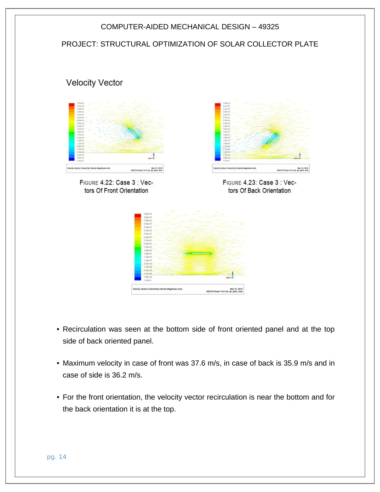
• Recirculation was seen at the bottom side of front oriented panel and at the top
side of back oriented panel.
• Maximum velocity in case of front was 37.6 m/s, in case of back is 35.9 m/s and in
case of side is 36.2 m/s.
• For the front orientation, the velocity vector recirculation is near the bottom and for
the back orientation it is at the top.
pg. 14
PROJECT: STRUCTURAL OPTIMIZATION OF SOLAR COLLECTOR PLATE
• Recirculation was seen at the bottom side of front oriented panel and at the top
side of back oriented panel.
• Maximum velocity in case of front was 37.6 m/s, in case of back is 35.9 m/s and in
case of side is 36.2 m/s.
• For the front orientation, the velocity vector recirculation is near the bottom and for
the back orientation it is at the top.
pg. 14
COMPUTER-AIDED MECHANICAL DESIGN – 49325
PROJECT: STRUCTURAL OPTIMIZATION OF SOLAR COLLECTOR PLATE
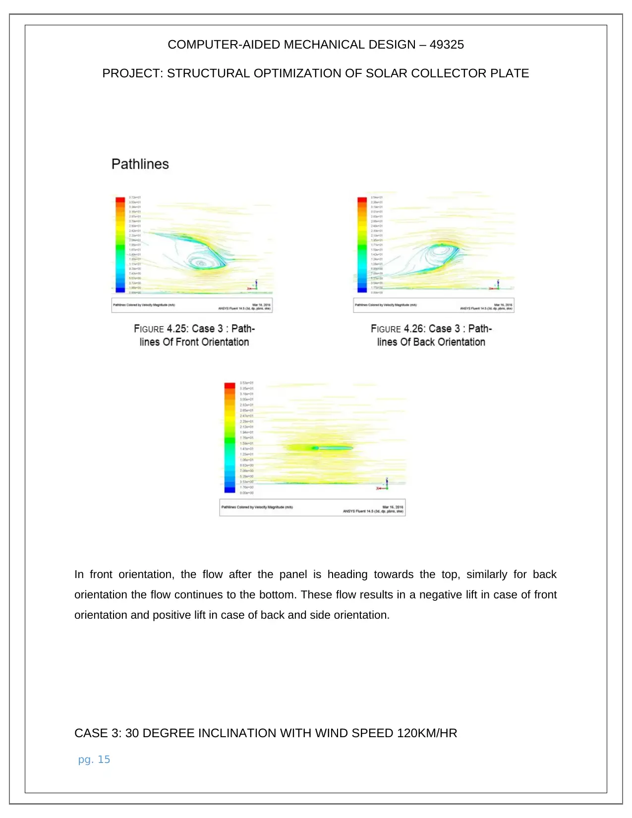
In front orientation, the flow after the panel is heading towards the top, similarly for back
orientation the flow continues to the bottom. These flow results in a negative lift in case of front
orientation and positive lift in case of back and side orientation.
CASE 3: 30 DEGREE INCLINATION WITH WIND SPEED 120KM/HR
pg. 15
PROJECT: STRUCTURAL OPTIMIZATION OF SOLAR COLLECTOR PLATE
In front orientation, the flow after the panel is heading towards the top, similarly for back
orientation the flow continues to the bottom. These flow results in a negative lift in case of front
orientation and positive lift in case of back and side orientation.
CASE 3: 30 DEGREE INCLINATION WITH WIND SPEED 120KM/HR
pg. 15
COMPUTER-AIDED MECHANICAL DESIGN – 49325
PROJECT: STRUCTURAL OPTIMIZATION OF SOLAR COLLECTOR PLATE
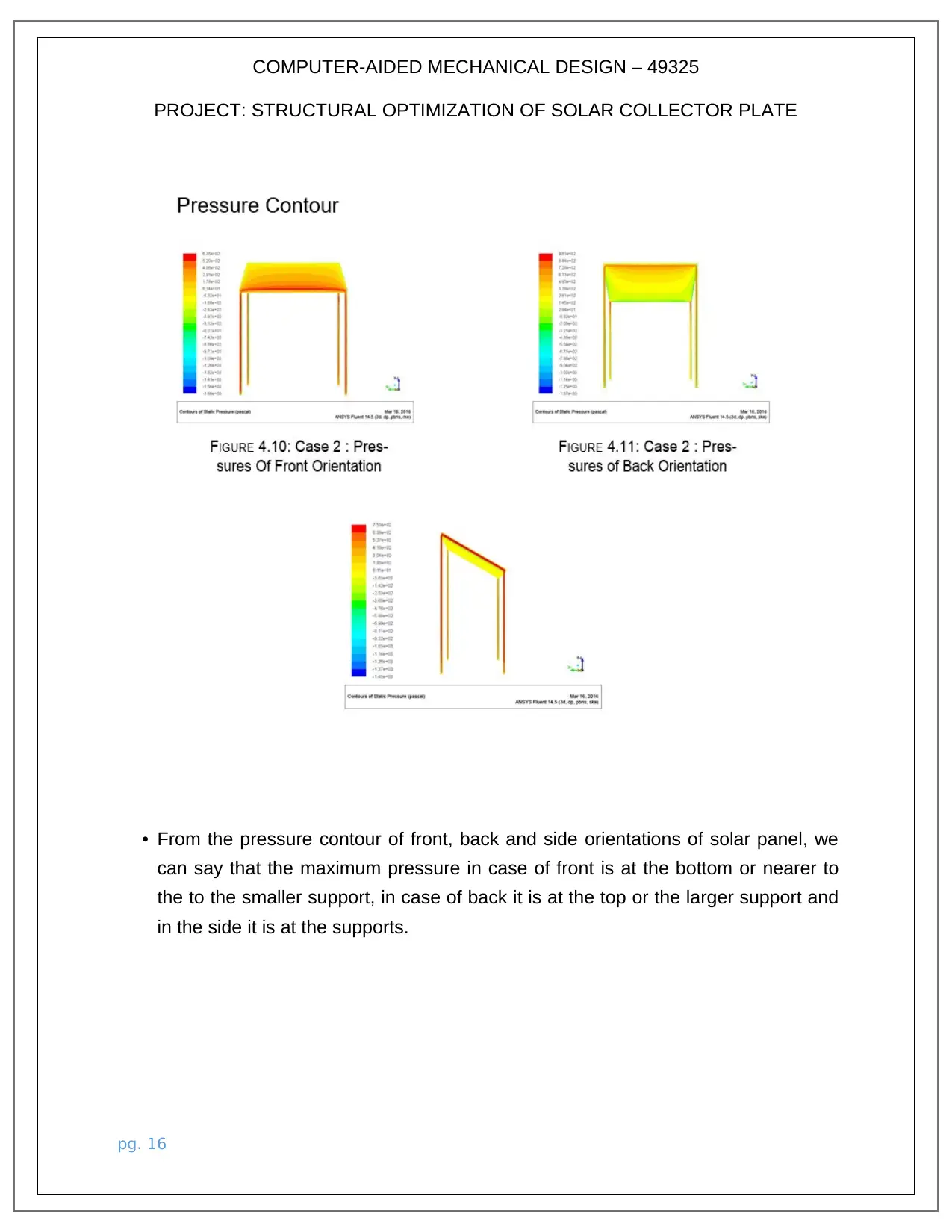
• From the pressure contour of front, back and side orientations of solar panel, we
can say that the maximum pressure in case of front is at the bottom or nearer to
the to the smaller support, in case of back it is at the top or the larger support and
in the side it is at the supports.
pg. 16
PROJECT: STRUCTURAL OPTIMIZATION OF SOLAR COLLECTOR PLATE
• From the pressure contour of front, back and side orientations of solar panel, we
can say that the maximum pressure in case of front is at the bottom or nearer to
the to the smaller support, in case of back it is at the top or the larger support and
in the side it is at the supports.
pg. 16
Secure Best Marks with AI Grader
Need help grading? Try our AI Grader for instant feedback on your assignments.
COMPUTER-AIDED MECHANICAL DESIGN – 49325
PROJECT: STRUCTURAL OPTIMIZATION OF SOLAR COLLECTOR PLATE
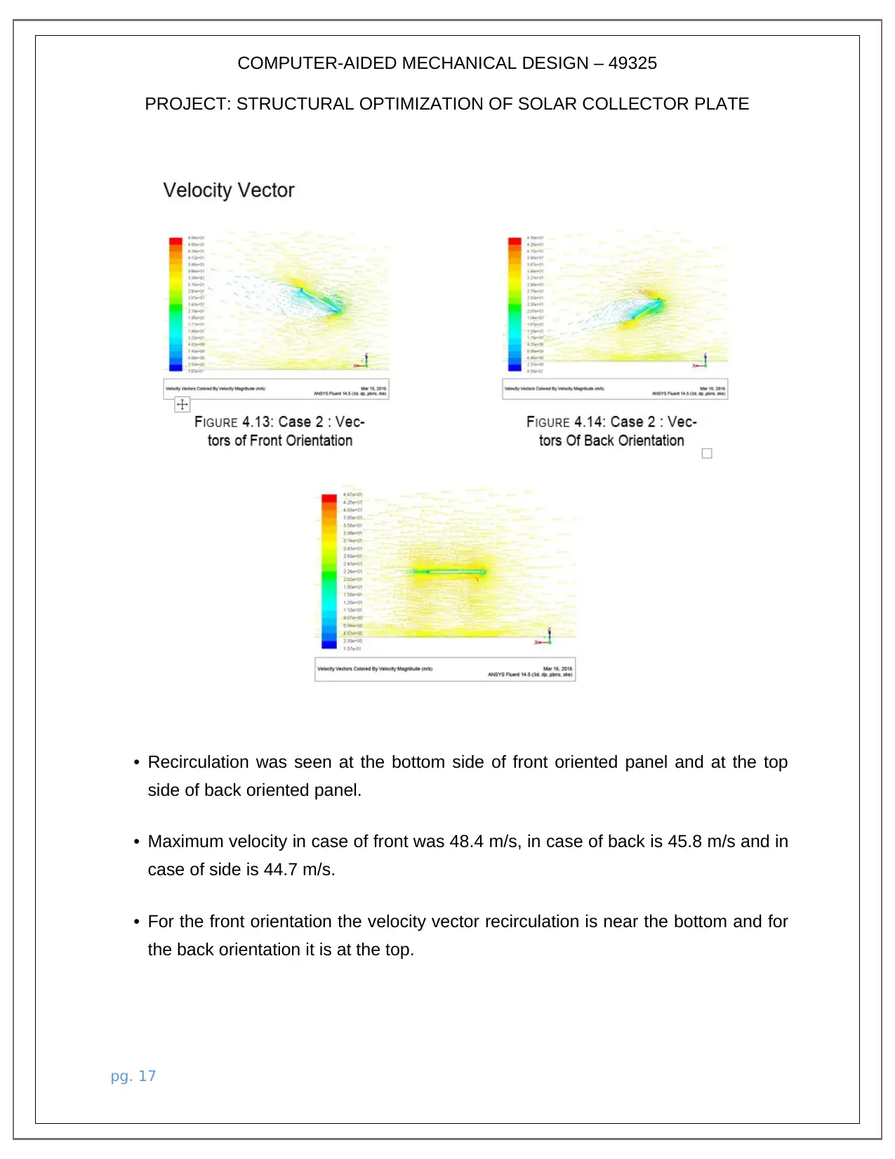
• Recirculation was seen at the bottom side of front oriented panel and at the top
side of back oriented panel.
• Maximum velocity in case of front was 48.4 m/s, in case of back is 45.8 m/s and in
case of side is 44.7 m/s.
• For the front orientation the velocity vector recirculation is near the bottom and for
the back orientation it is at the top.
pg. 17
PROJECT: STRUCTURAL OPTIMIZATION OF SOLAR COLLECTOR PLATE
• Recirculation was seen at the bottom side of front oriented panel and at the top
side of back oriented panel.
• Maximum velocity in case of front was 48.4 m/s, in case of back is 45.8 m/s and in
case of side is 44.7 m/s.
• For the front orientation the velocity vector recirculation is near the bottom and for
the back orientation it is at the top.
pg. 17
COMPUTER-AIDED MECHANICAL DESIGN – 49325
PROJECT: STRUCTURAL OPTIMIZATION OF SOLAR COLLECTOR PLATE
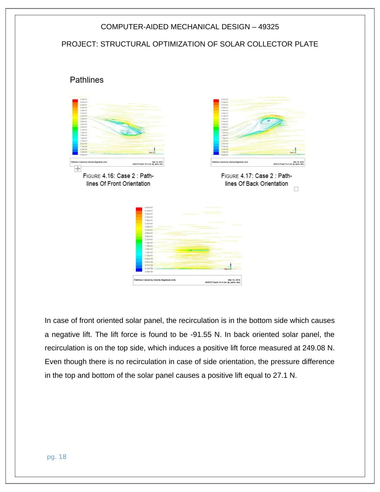
In case of front oriented solar panel, the recirculation is in the bottom side which causes
a negative lift. The lift force is found to be -91.55 N. In back oriented solar panel, the
recirculation is on the top side, which induces a positive lift force measured at 249.08 N.
Even though there is no recirculation in case of side orientation, the pressure difference
in the top and bottom of the solar panel causes a positive lift equal to 27.1 N.
pg. 18
PROJECT: STRUCTURAL OPTIMIZATION OF SOLAR COLLECTOR PLATE
In case of front oriented solar panel, the recirculation is in the bottom side which causes
a negative lift. The lift force is found to be -91.55 N. In back oriented solar panel, the
recirculation is on the top side, which induces a positive lift force measured at 249.08 N.
Even though there is no recirculation in case of side orientation, the pressure difference
in the top and bottom of the solar panel causes a positive lift equal to 27.1 N.
pg. 18
COMPUTER-AIDED MECHANICAL DESIGN – 49325
PROJECT: STRUCTURAL OPTIMIZATION OF SOLAR COLLECTOR PLATE
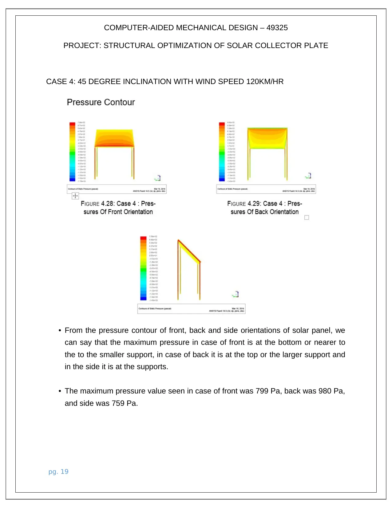
CASE 4: 45 DEGREE INCLINATION WITH WIND SPEED 120KM/HR
• From the pressure contour of front, back and side orientations of solar panel, we
can say that the maximum pressure in case of front is at the bottom or nearer to
the to the smaller support, in case of back it is at the top or the larger support and
in the side it is at the supports.
• The maximum pressure value seen in case of front was 799 Pa, back was 980 Pa,
and side was 759 Pa.
pg. 19
PROJECT: STRUCTURAL OPTIMIZATION OF SOLAR COLLECTOR PLATE
CASE 4: 45 DEGREE INCLINATION WITH WIND SPEED 120KM/HR
• From the pressure contour of front, back and side orientations of solar panel, we
can say that the maximum pressure in case of front is at the bottom or nearer to
the to the smaller support, in case of back it is at the top or the larger support and
in the side it is at the supports.
• The maximum pressure value seen in case of front was 799 Pa, back was 980 Pa,
and side was 759 Pa.
pg. 19
Paraphrase This Document
Need a fresh take? Get an instant paraphrase of this document with our AI Paraphraser
COMPUTER-AIDED MECHANICAL DESIGN – 49325
PROJECT: STRUCTURAL OPTIMIZATION OF SOLAR COLLECTOR PLATE
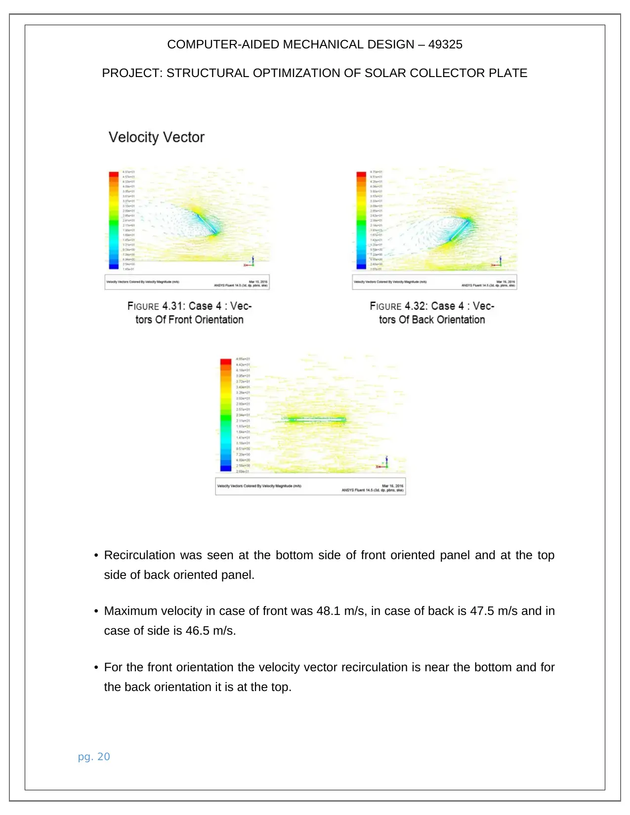
• Recirculation was seen at the bottom side of front oriented panel and at the top
side of back oriented panel.
• Maximum velocity in case of front was 48.1 m/s, in case of back is 47.5 m/s and in
case of side is 46.5 m/s.
• For the front orientation the velocity vector recirculation is near the bottom and for
the back orientation it is at the top.
pg. 20
PROJECT: STRUCTURAL OPTIMIZATION OF SOLAR COLLECTOR PLATE
• Recirculation was seen at the bottom side of front oriented panel and at the top
side of back oriented panel.
• Maximum velocity in case of front was 48.1 m/s, in case of back is 47.5 m/s and in
case of side is 46.5 m/s.
• For the front orientation the velocity vector recirculation is near the bottom and for
the back orientation it is at the top.
pg. 20
COMPUTER-AIDED MECHANICAL DESIGN – 49325
PROJECT: STRUCTURAL OPTIMIZATION OF SOLAR COLLECTOR PLATE
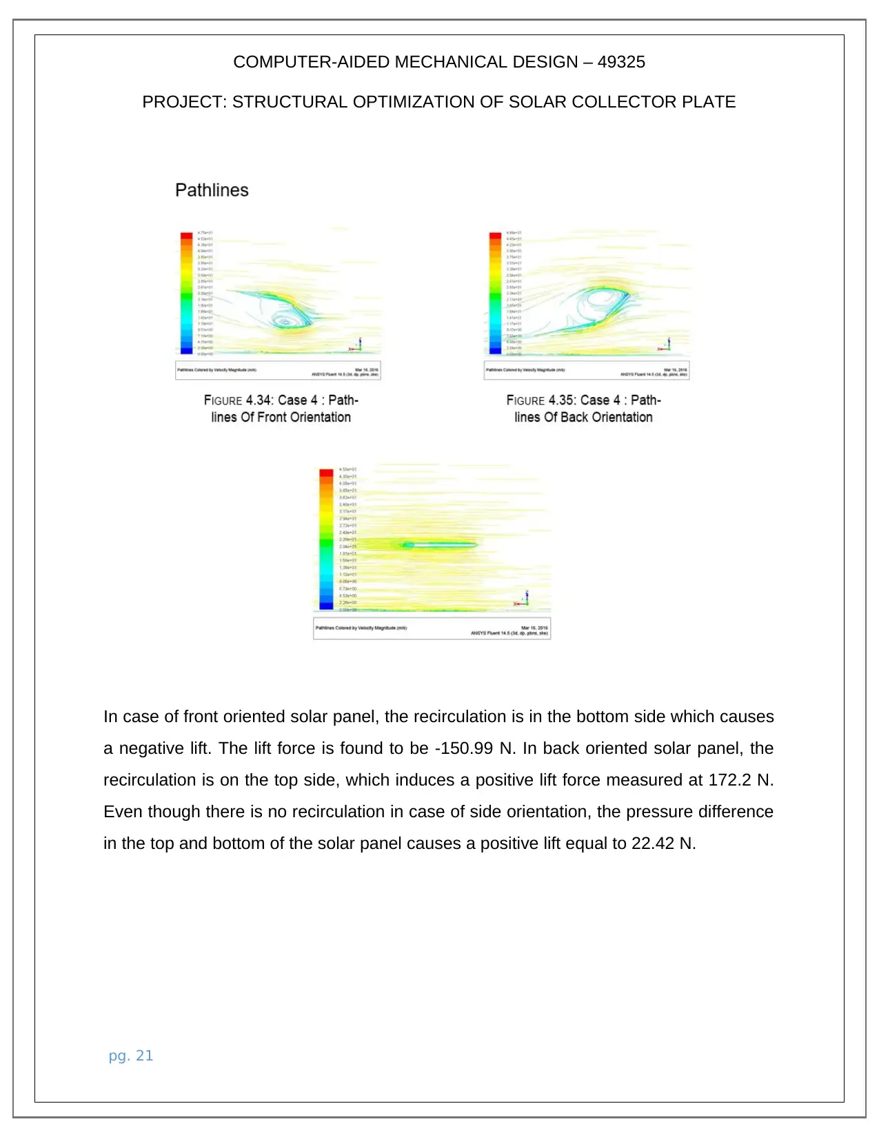
In case of front oriented solar panel, the recirculation is in the bottom side which causes
a negative lift. The lift force is found to be -150.99 N. In back oriented solar panel, the
recirculation is on the top side, which induces a positive lift force measured at 172.2 N.
Even though there is no recirculation in case of side orientation, the pressure difference
in the top and bottom of the solar panel causes a positive lift equal to 22.42 N.
pg. 21
PROJECT: STRUCTURAL OPTIMIZATION OF SOLAR COLLECTOR PLATE
In case of front oriented solar panel, the recirculation is in the bottom side which causes
a negative lift. The lift force is found to be -150.99 N. In back oriented solar panel, the
recirculation is on the top side, which induces a positive lift force measured at 172.2 N.
Even though there is no recirculation in case of side orientation, the pressure difference
in the top and bottom of the solar panel causes a positive lift equal to 22.42 N.
pg. 21
COMPUTER-AIDED MECHANICAL DESIGN – 49325
PROJECT: STRUCTURAL OPTIMIZATION OF SOLAR COLLECTOR PLATE
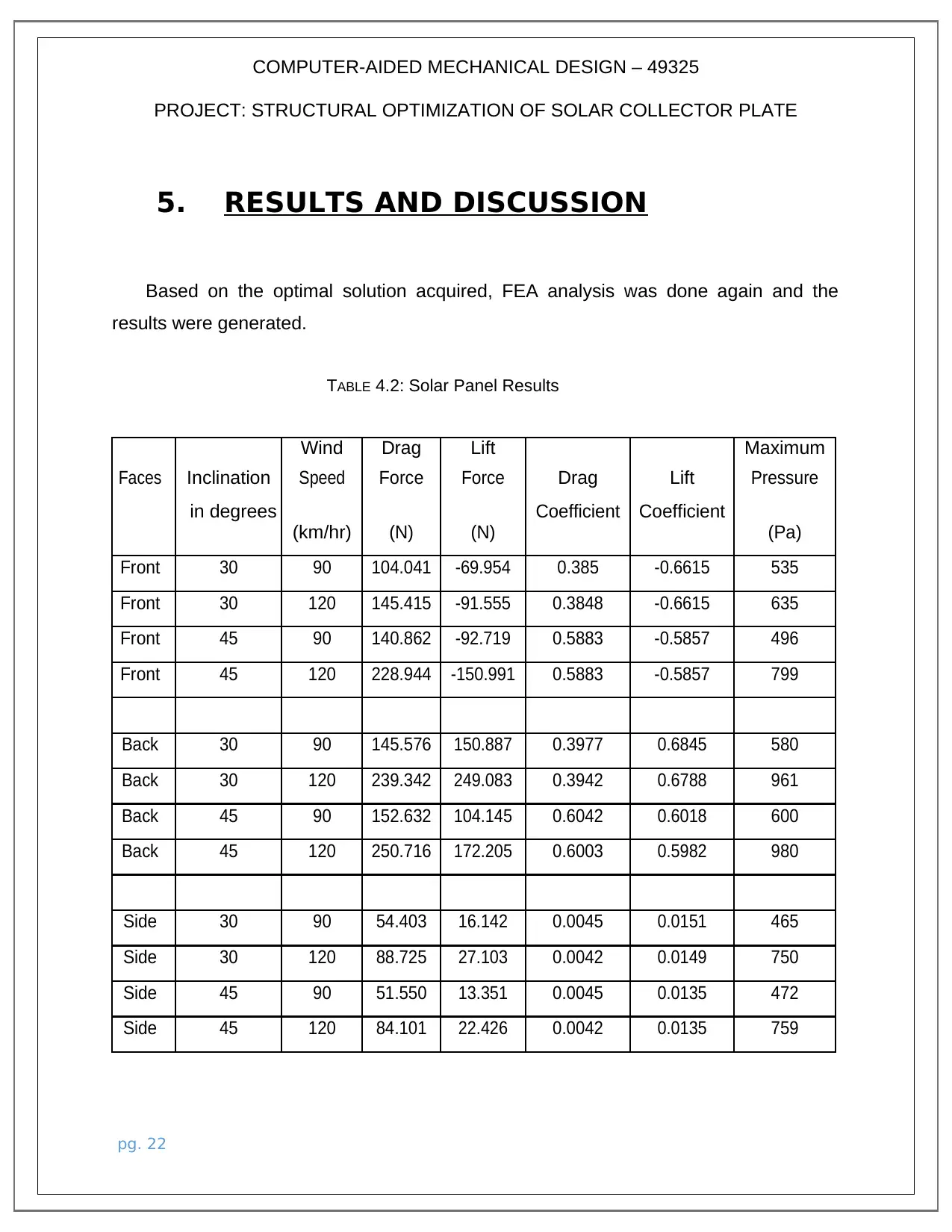
5. RESULTS AND DISCUSSION
Based on the optimal solution acquired, FEA analysis was done again and the
results were generated.
TABLE 4.2: Solar Panel Results
Inclination
Wind Drag Lift
Drag Lift
Maximum
Faces Speed Force Force Pressure
in degrees
(km/hr) (N) (N)
Coefficient Coefficient
(Pa)
Front 30 90 104.041 -69.954 0.385 -0.6615 535
Front 30 120 145.415 -91.555 0.3848 -0.6615 635
Front 45 90 140.862 -92.719 0.5883 -0.5857 496
Front 45 120 228.944 -150.991 0.5883 -0.5857 799
Back 30 90 145.576 150.887 0.3977 0.6845 580
Back 30 120 239.342 249.083 0.3942 0.6788 961
Back 45 90 152.632 104.145 0.6042 0.6018 600
Back 45 120 250.716 172.205 0.6003 0.5982 980
Side 30 90 54.403 16.142 0.0045 0.0151 465
Side 30 120 88.725 27.103 0.0042 0.0149 750
Side 45 90 51.550 13.351 0.0045 0.0135 472
Side 45 120 84.101 22.426 0.0042 0.0135 759
pg. 22
PROJECT: STRUCTURAL OPTIMIZATION OF SOLAR COLLECTOR PLATE
5. RESULTS AND DISCUSSION
Based on the optimal solution acquired, FEA analysis was done again and the
results were generated.
TABLE 4.2: Solar Panel Results
Inclination
Wind Drag Lift
Drag Lift
Maximum
Faces Speed Force Force Pressure
in degrees
(km/hr) (N) (N)
Coefficient Coefficient
(Pa)
Front 30 90 104.041 -69.954 0.385 -0.6615 535
Front 30 120 145.415 -91.555 0.3848 -0.6615 635
Front 45 90 140.862 -92.719 0.5883 -0.5857 496
Front 45 120 228.944 -150.991 0.5883 -0.5857 799
Back 30 90 145.576 150.887 0.3977 0.6845 580
Back 30 120 239.342 249.083 0.3942 0.6788 961
Back 45 90 152.632 104.145 0.6042 0.6018 600
Back 45 120 250.716 172.205 0.6003 0.5982 980
Side 30 90 54.403 16.142 0.0045 0.0151 465
Side 30 120 88.725 27.103 0.0042 0.0149 750
Side 45 90 51.550 13.351 0.0045 0.0135 472
Side 45 120 84.101 22.426 0.0042 0.0135 759
pg. 22
Secure Best Marks with AI Grader
Need help grading? Try our AI Grader for instant feedback on your assignments.
COMPUTER-AIDED MECHANICAL DESIGN – 49325
PROJECT: STRUCTURAL OPTIMIZATION OF SOLAR COLLECTOR PLATE
• From the above results, maximum peak pressure acting over the panels
has been observed for 45o inclination, back orientation, and wind velocity
of 120 km/hr.
• Minimum peak pressure is observed for 30o inclination, side orientation,
and wind velocity of 90 km/hr.
• Maximum drag force was observed for 45o inclination, back orientation,
wind velocity of 120 km/hr. And minimum drag force was observed for
45o inclination, side orientation, and wind velocity of 90 km/hr.
• Maximum lift force was observed for 30o inclination, back orientation,
wind ve-locity of 120 km/hr. And minimum lift force was observed for 45o
inclination, side orientation, and wind velocity of 90 km/hr
• The 30o angle is the optimum inclination recommended for the solar
panel after considering different orientations and wind velocity.
pg. 23
COMPUTER-AIDED MECHANICAL DESIGN – 49325
PROJECT: STRUCTURAL OPTIMIZATION OF SOLAR COLLECTOR PLATE
6. Conclusions
a. Development of the fluid domain and the solar panel with respect to the
actual dimensions is done.
b. Discretization of the entire fluid domain by using unstructured tetrahedral
mesh and grid sensitivity has been obtained as 122853.
c. Initial conditions were finalized and the elements were grouped per
boundary conditions.
d. The flow domain has been solved with CFD solver by assigning
pressure coupling method and finite volume method. Finite volume
method has been adopted to solve the Navier stoke equation.
e. Results have been generated over the solar panel faces at top, bottom,
side for pressure, velocity and pathlines.
f. Lift and drag forces calculated for different orientations of solar panel are
obtained, the maximum pressure that is acting over the panel is identified.
g. 30o inclination is the most optimum orientation suited for high wind
speed conditions.
pg. 24
1 out of 24
Your All-in-One AI-Powered Toolkit for Academic Success.
+13062052269
info@desklib.com
Available 24*7 on WhatsApp / Email
![[object Object]](/_next/static/media/star-bottom.7253800d.svg)
Unlock your academic potential
© 2024 | Zucol Services PVT LTD | All rights reserved.