Comprehensive Report: Heat Transfer and Fluid Mechanics in Engineering
VerifiedAdded on 2020/05/16
|15
|1489
|333
Report
AI Summary
This report provides an introduction to heat transfer and fluid mechanics, exploring various heating and cooling systems like forced air furnaces, hot water boilers, and electric heat pumps. It delves into calculations for power requirements in duct systems based on varying flow rates and temperatures. The report classifies duct systems based on pressure and analyzes fluid flow characteristics, including velocity, Reynolds number, and boundary layer parameters such as displacement and momentum thickness. Furthermore, the report includes a SolidWorks Flow Simulation project, comparing theoretical calculations with simulation results for a rectangular duct, detailing the analysis environment, model information, simulation parameters, boundary conditions, and results, concluding with a comparison of theoretical and simulated values.
Heat Transfer and Fluid Mechanics
Introduction: The Degree Hotness and Coldness Is called heating.
Types of heating system: The most popular space heating systems are
1. Forced air furnaces: A forced-air central heating system is one which uses air as its heat
transfer medium. These systems rely on ductwork, vents, and plenums as means of air
distribution, separate from the actual heating and air conditioning systems. The return plenum
carries the air from several large return grills (vents) to a central air handler for re-heating. The
supply plenum directs air from the central unit to the rooms which the system is designed to heat.
Regardless of type, all air handlers consist of an air filter, blower, heat exchanger/element/coil,
and various controls. Like any other kind of central heating system, thermostats are used to
control forced air heating systems. Forced air heating is probably the type of central heating most
commonly installed in North America. It is much less common in Europe, where hydronic heating
predominates, especially in the form of hot-water radiators.
2. Hot water boilers: - hot water boilers involve the heating of water and creation of steam
through the burning of fuel. The heated water is transmitted through boiler tubes, while the steam
created is circulated throughout the facility with the assistance of radiators.
3. Electric heat pumps: heat pumps use electricity to move heat from a cool space to a warm
space, making the cool space cooler and the warm space warmer.
Cooling: Cooling is the transfer of thermal energy via radiation, conduction or convection.
Types of Cooling System:-
1. Room Air Conditioners
2. Evaporative Coolers.
3. Ductless Mini-Split Air Conditioners.
4. State of the Art Cooling.
Q. No.:-1
Solution
20
0.5m
0.5m
Paraphrase This Document
Need a fresh take? Get an instant paraphrase of this document with our AI Paraphraser
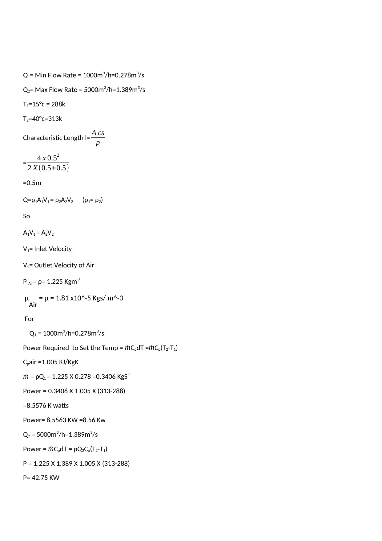
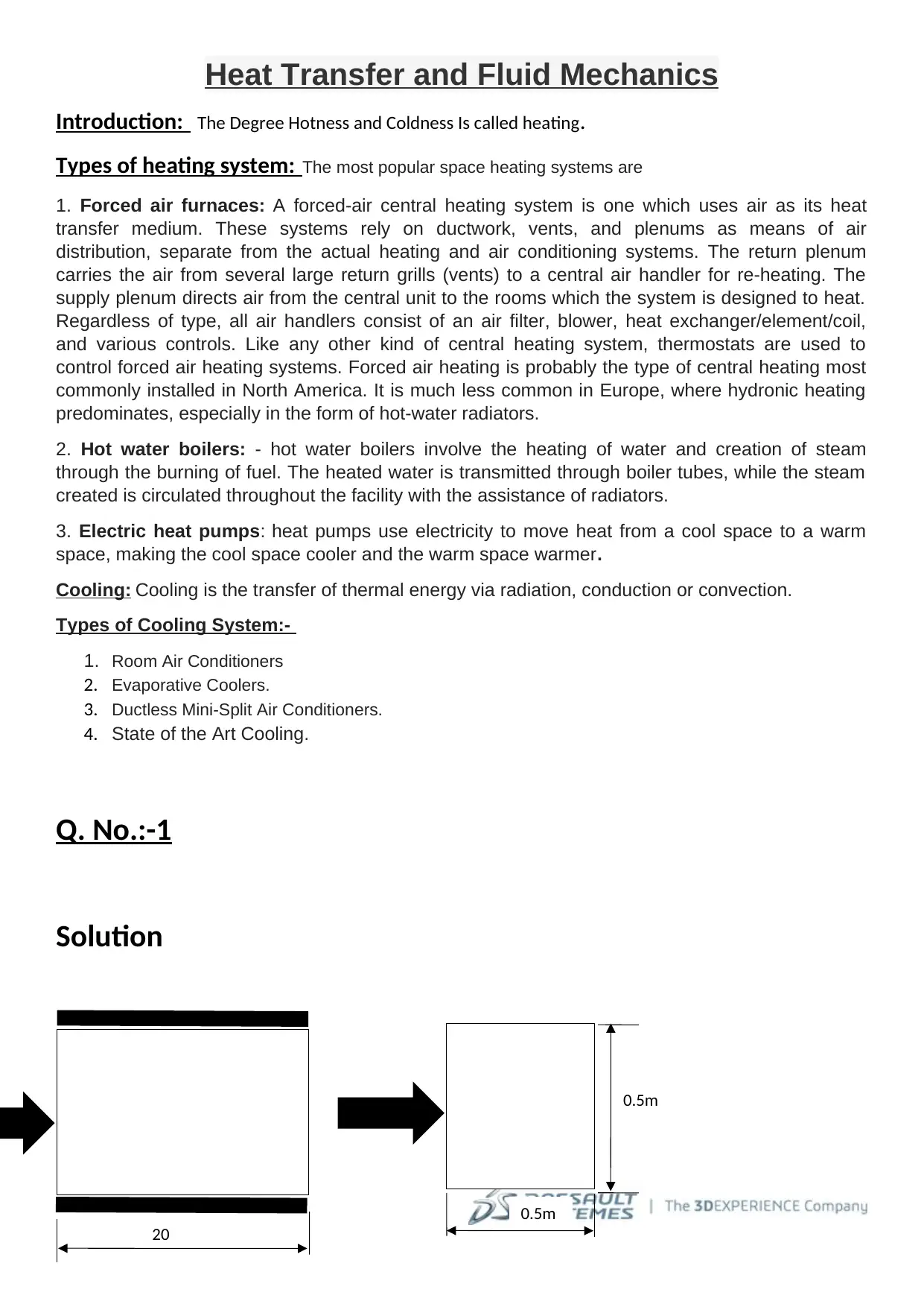
Q1= Min Flow Rate = 1000m3/h=0.278m3/s
Q2= Max Flow Rate = 5000m3/h=1.389m3/s
T1=15°c = 288k
T2=40°c=313k
Characteristic Length l= A cs
p
= 4 x 0.52
2 X (0.5+0.5)
=0.5m
Q=ρ1A1V1 = ρ2A2V2 (ρ1= ρ2)
So
A1V1 = A2V2
V1= Inlet Velocity
V2= Outlet Velocity of Air
Ρ Air= ρ= 1.225 Kgm-3
μAir = μ = 1.81 x10^-5 Kgs/ m^-3
For
Q1 = 1000m3/h=0.278m3/s
Power Required to Set the Temp = ˙mCpdT = ˙mCp(T2-T1)
Cpair =1.005 KJ/KgK
˙m = ρQ1 = 1.225 X 0.278 =0.3406 KgS-1
Power = 0.3406 X 1.005 X (313-288)
=8.5576 K watts
Power= 8.5563 KW =8.56 Kw
Q2 = 5000m3/h=1.389m3/s
Power = ˙mCpdT = ρQ2Cp(T2-T1)
P = 1.225 X 1.389 X 1.005 X (313-288)
P= 42.75 KW
Duct System
Duct System: Ducts are conduits or passages used in heating, ventilation, and air conditioning (HVAC) to
deliver and remove air. The needed airflows include, for example, supply air, return air, and exhaust air.
Ducts commonly also deliver ventilation air as part of the supply air. A duct system is also called ductwork.
Classification of duct systems: Ducts are classified based on the load on duct due to air pressure
and turbulence. The classification varies from application to application, such as for residences, commercial
systems, industrial systems etc. For example, one such classification is given below.
1. Low pressure systems: Velocity ≤ 10 m/s, static pressure ≤ 5 cm HO (g) 2
2. Medium pressure systems: Velocity ≤ 10 m/s, static pressure ≤ 15 cm HO (g) 2
3. High pressure systems: Velocity > 10 m/s, static pressure 15<p ≤ 25 cm HO (g)
Q. No. 2:-
Solution
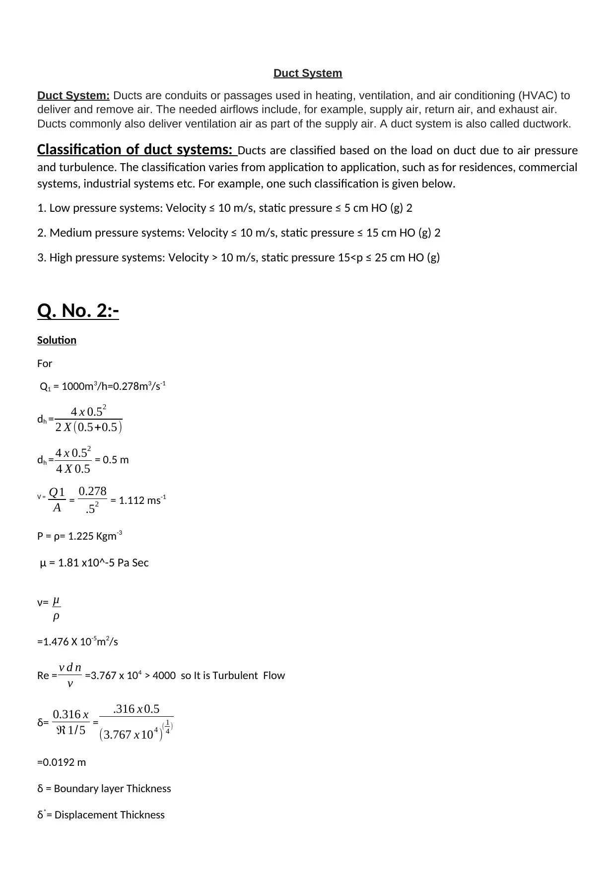
For
Q1 = 1000m3/h=0.278m3/s-1
dh = 4 x 0.52
2 X (0.5+0.5)
dh = 4 x 0.52
4 X 0.5 = 0.5 m
V = Q1
A = 0.278
.52 = 1.112 ms-1
Ρ = ρ= 1.225 Kgm-3
μ = 1.81 x10^-5 Pa Sec
ν= μ
ρ
=1.476 X 10⁻⁵m2/s
Re = v d n
ν =3.767 x 10⁴ > 4000 so It is Turbulent Flow
δ= 0.316 x
ℜ1/5 =
.316 x 0.5
(3.767 x 10⁴ )( 1
4 )
=0.0192 m
δ = Boundary layer Thickness
δ*= Displacement Thickness
Duct System: Ducts are conduits or passages used in heating, ventilation, and air conditioning (HVAC) to
deliver and remove air. The needed airflows include, for example, supply air, return air, and exhaust air.
Ducts commonly also deliver ventilation air as part of the supply air. A duct system is also called ductwork.
Classification of duct systems: Ducts are classified based on the load on duct due to air pressure
and turbulence. The classification varies from application to application, such as for residences, commercial
systems, industrial systems etc. For example, one such classification is given below.
1. Low pressure systems: Velocity ≤ 10 m/s, static pressure ≤ 5 cm HO (g) 2
2. Medium pressure systems: Velocity ≤ 10 m/s, static pressure ≤ 15 cm HO (g) 2
3. High pressure systems: Velocity > 10 m/s, static pressure 15<p ≤ 25 cm HO (g)
Q. No. 2:-
Solution
For
Q1 = 1000m3/h=0.278m3/s-1
dh = 4 x 0.52
2 X (0.5+0.5)
dh = 4 x 0.52
4 X 0.5 = 0.5 m
V = Q1
A = 0.278
.52 = 1.112 ms-1
Ρ = ρ= 1.225 Kgm-3
μ = 1.81 x10^-5 Pa Sec
ν= μ
ρ
=1.476 X 10⁻⁵m2/s
Re = v d n
ν =3.767 x 10⁴ > 4000 so It is Turbulent Flow
δ= 0.316 x
ℜ1/5 =
.316 x 0.5
(3.767 x 10⁴ )( 1
4 )
=0.0192 m
δ = Boundary layer Thickness
δ*= Displacement Thickness
⊘ This is a preview!⊘
Do you want full access?
Subscribe today to unlock all pages.
Trusted by 1+ million students worldwide
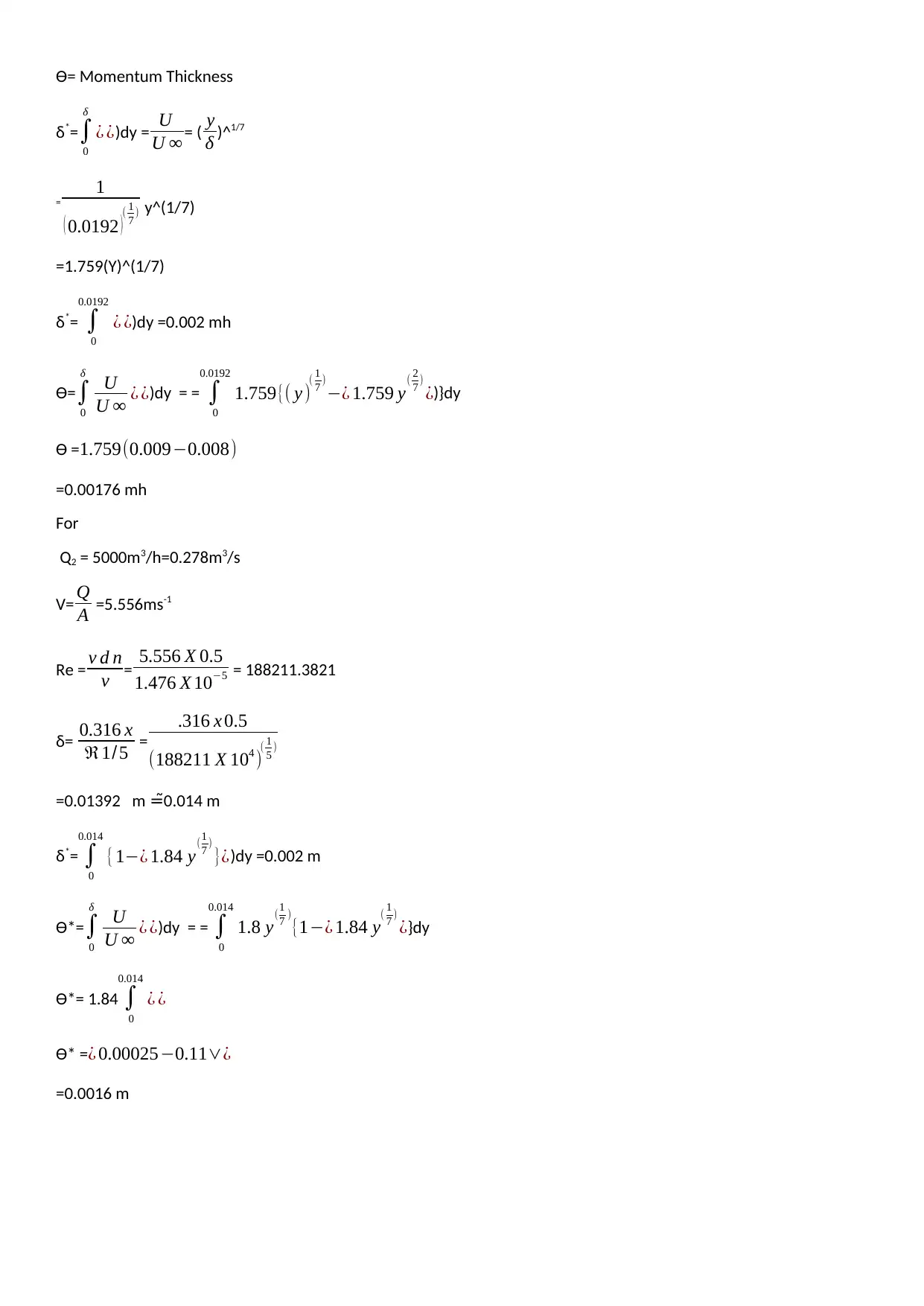
Ɵ= Momentum Thickness
δ*=∫
0
δ
¿ ¿)dy = U
U ∞ = ( y
δ )^1/7
=
1
( 0.0192 )( 1
7 ) y^(1/7)
=1.759(Y)^(1/7)
δ*= ∫
0
0.0192
¿ ¿)dy =0.002 mh
Ɵ=∫
0
δ
U
U ∞ ¿ ¿)dy = = ∫
0
0.0192
1.759{( y )( 1
7 )
−¿ 1.759 y( 2
7 )
¿)}dy
Ɵ = 1.759(0.009−0.008)
=0.00176 mh
For
Q2 = 5000m3/h=0.278m3/s
V= Q
A =5.556ms-1
Re = v d n
ν = 5.556 X 0.5
1.476 X 10−5 = 188211.3821
δ= 0.316 x
ℜ1/5 =
.316 x 0.5
(188211 X 104 )( 1
5 )
=0.01392 m 0.014 m=̃
δ*= ∫
0
0.014
{1−¿ 1.84 y(1
7 )
}¿)dy =0.002 m
Ɵ*=∫
0
δ
U
U ∞ ¿ ¿)dy = = ∫
0
0.014
1.8 y(1
7 )
{1−¿ 1.84 y( 1
7 )
¿}dy
Ɵ*= 1.84 ∫
0
0.014
¿ ¿
Ɵ* =¿ 0.00025−0.11∨¿
=0.0016 m
Paraphrase This Document
Need a fresh take? Get an instant paraphrase of this document with our AI Paraphraser

Solid Works Analysis Report
Fluid Flow Simulation Project
Report
SolidWorks Flow Simulation
Project Report
August 16, 2024
Fluid Flow Simulation Project
Report
SolidWorks Flow Simulation
Project Report
August 16, 2024
⊘ This is a preview!⊘
Do you want full access?
Subscribe today to unlock all pages.
Trusted by 1+ million students worldwide
Table of Contents
1 General Information.................................................................................................1
1.1 Analysis Environment................................................................................1
1.2 Model Information.....................................................................................1
1.3 Project Comments:....................................................................................1
1.4 Size of Computational Domain..................................................................1
1.5 Simulation Parameters..............................................................................1
1.5.1 Mesh Settings.........................................................................................1
1.5.2 Material Settings....................................................................................2
1.5.3 Initial Conditions....................................................................................2
1.5.4 Boundary Conditions..............................................................................2
1.5.5 Volumetric Heat Sources........................................................................2
1.5.6 Engineering Goals..................................................................................2
1.6 Analysis Time............................................................................................2
2 Results...............................................................................................................2
2.1 Analysis Goals...........................................................................................2
2.2 Global Min-Max-Table..................................................................................2
2.3 Results......................................................................................................2
2.4 Conclusion.................................................................................................2
3 Appendix.............................................................................................................2
3.1 Material Data............................................................................................2
Paraphrase This Document
Need a fresh take? Get an instant paraphrase of this document with our AI Paraphraser
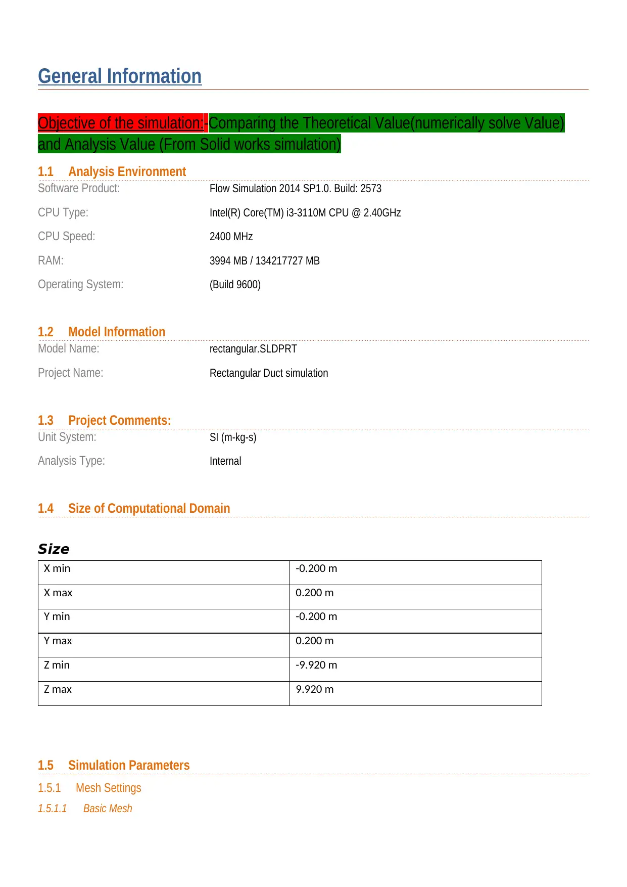
General Information
Objective of the simulation:-Comparing the Theoretical Value(numerically solve Value)
and Analysis Value (From Solid works simulation)
1.1 Analysis Environment
Software Product: Flow Simulation 2014 SP1.0. Build: 2573
CPU Type: Intel(R) Core(TM) i3-3110M CPU @ 2.40GHz
CPU Speed: 2400 MHz
RAM: 3994 MB / 134217727 MB
Operating System: (Build 9600)
1.2 Model Information
Model Name: rectangular.SLDPRT
Project Name: Rectangular Duct simulation
1.3 Project Comments:
Unit System: SI (m-kg-s)
Analysis Type: Internal
1.4 Size of Computational Domain
Size
X min -0.200 m
X max 0.200 m
Y min -0.200 m
Y max 0.200 m
Z min -9.920 m
Z max 9.920 m
1.5 Simulation Parameters
1.5.1 Mesh Settings
1.5.1.1 Basic Mesh
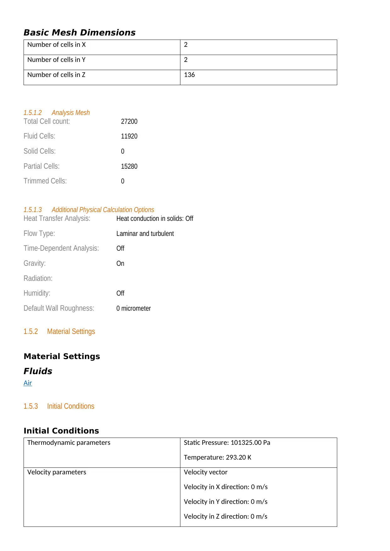
Basic Mesh Dimensions
Number of cells in X 2
Number of cells in Y 2
Number of cells in Z 136
1.5.1.2 Analysis Mesh
Total Cell count: 27200
Fluid Cells: 11920
Solid Cells: 0
Partial Cells: 15280
Trimmed Cells: 0
1.5.1.3 Additional Physical Calculation Options
Heat Transfer Analysis: Heat conduction in solids: Off
Flow Type: Laminar and turbulent
Time-Dependent Analysis: Off
Gravity: On
Radiation:
Humidity: Off
Default Wall Roughness: 0 micrometer
1.5.2 Material Settings
Material Settings
Fluids
Air
1.5.3 Initial Conditions
Initial Conditions
Thermodynamic parameters Static Pressure: 101325.00 Pa
Temperature: 293.20 K
Velocity parameters Velocity vector
Velocity in X direction: 0 m/s
Velocity in Y direction: 0 m/s
Velocity in Z direction: 0 m/s
⊘ This is a preview!⊘
Do you want full access?
Subscribe today to unlock all pages.
Trusted by 1+ million students worldwide
Turbulence parameters Turbulence intensity and length
Intensity: 2.00 %
Length: 0.005 m
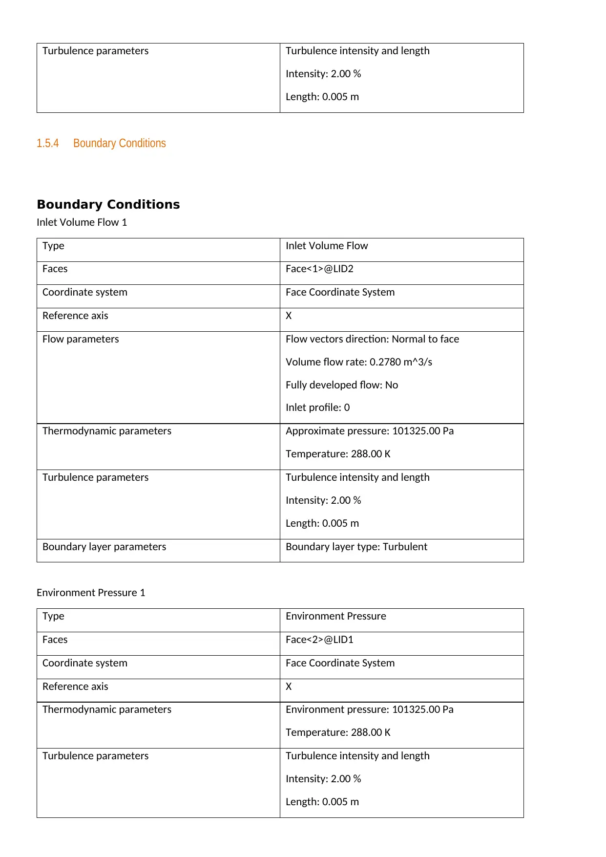
1.5.4 Boundary Conditions
Boundary Conditions
Inlet Volume Flow 1
Type Inlet Volume Flow
Faces Face<1>@LID2
Coordinate system Face Coordinate System
Reference axis X
Flow parameters Flow vectors direction: Normal to face
Volume flow rate: 0.2780 m^3/s
Fully developed flow: No
Inlet profile: 0
Thermodynamic parameters Approximate pressure: 101325.00 Pa
Temperature: 288.00 K
Turbulence parameters Turbulence intensity and length
Intensity: 2.00 %
Length: 0.005 m
Boundary layer parameters Boundary layer type: Turbulent
Environment Pressure 1
Type Environment Pressure
Faces Face<2>@LID1
Coordinate system Face Coordinate System
Reference axis X
Thermodynamic parameters Environment pressure: 101325.00 Pa
Temperature: 288.00 K
Turbulence parameters Turbulence intensity and length
Intensity: 2.00 %
Length: 0.005 m
Intensity: 2.00 %
Length: 0.005 m
1.5.4 Boundary Conditions
Boundary Conditions
Inlet Volume Flow 1
Type Inlet Volume Flow
Faces Face<1>@LID2
Coordinate system Face Coordinate System
Reference axis X
Flow parameters Flow vectors direction: Normal to face
Volume flow rate: 0.2780 m^3/s
Fully developed flow: No
Inlet profile: 0
Thermodynamic parameters Approximate pressure: 101325.00 Pa
Temperature: 288.00 K
Turbulence parameters Turbulence intensity and length
Intensity: 2.00 %
Length: 0.005 m
Boundary layer parameters Boundary layer type: Turbulent
Environment Pressure 1
Type Environment Pressure
Faces Face<2>@LID1
Coordinate system Face Coordinate System
Reference axis X
Thermodynamic parameters Environment pressure: 101325.00 Pa
Temperature: 288.00 K
Turbulence parameters Turbulence intensity and length
Intensity: 2.00 %
Length: 0.005 m
Paraphrase This Document
Need a fresh take? Get an instant paraphrase of this document with our AI Paraphraser

Boundary layer parameters Boundary layer type: Turbulent
Analysis Time
Calculation Time: 140 s
Number of Iterations: 109
Warnings:
Analysis Time
Calculation Time: 140 s
Number of Iterations: 109
Warnings:
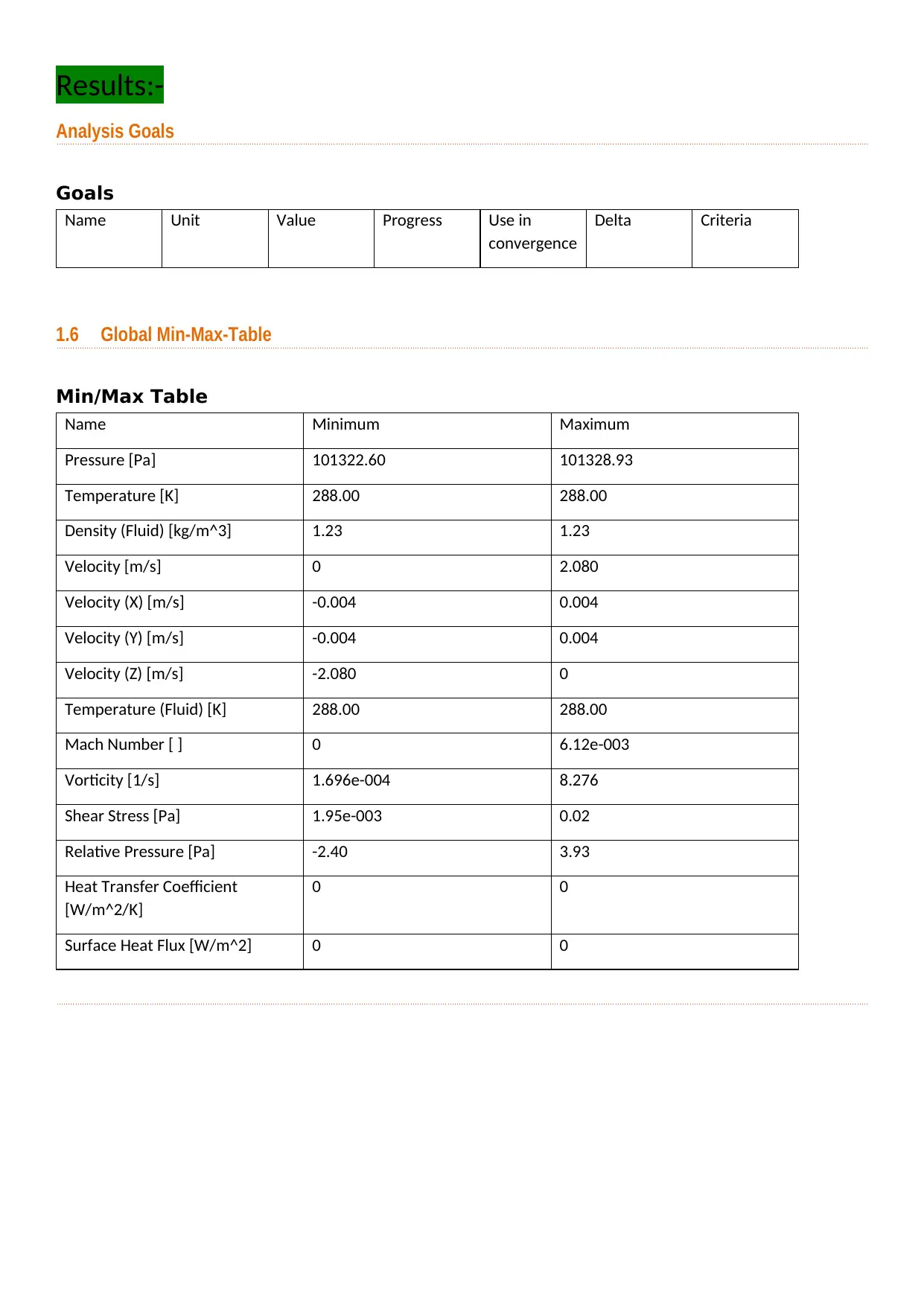
Results:-
Analysis Goals
Goals
Name Unit Value Progress Use in
convergence
Delta Criteria
1.6 Global Min-Max-Table
Min/Max Table
Name Minimum Maximum
Pressure [Pa] 101322.60 101328.93
Temperature [K] 288.00 288.00
Density (Fluid) [kg/m^3] 1.23 1.23
Velocity [m/s] 0 2.080
Velocity (X) [m/s] -0.004 0.004
Velocity (Y) [m/s] -0.004 0.004
Velocity (Z) [m/s] -2.080 0
Temperature (Fluid) [K] 288.00 288.00
Mach Number [ ] 0 6.12e-003
Vorticity [1/s] 1.696e-004 8.276
Shear Stress [Pa] 1.95e-003 0.02
Relative Pressure [Pa] -2.40 3.93
Heat Transfer Coefficient
[W/m^2/K]
0 0
Surface Heat Flux [W/m^2] 0 0
⊘ This is a preview!⊘
Do you want full access?
Subscribe today to unlock all pages.
Trusted by 1+ million students worldwide
1 out of 15

Your All-in-One AI-Powered Toolkit for Academic Success.
+13062052269
info@desklib.com
Available 24*7 on WhatsApp / Email
![[object Object]](/_next/static/media/star-bottom.7253800d.svg)
Unlock your academic potential
Copyright © 2020–2026 A2Z Services. All Rights Reserved. Developed and managed by ZUCOL.