HNC Electrical Engineering: Electrical and Electronic Principles
VerifiedAdded on 2023/04/22
|12
|1195
|325
Homework Assignment
AI Summary
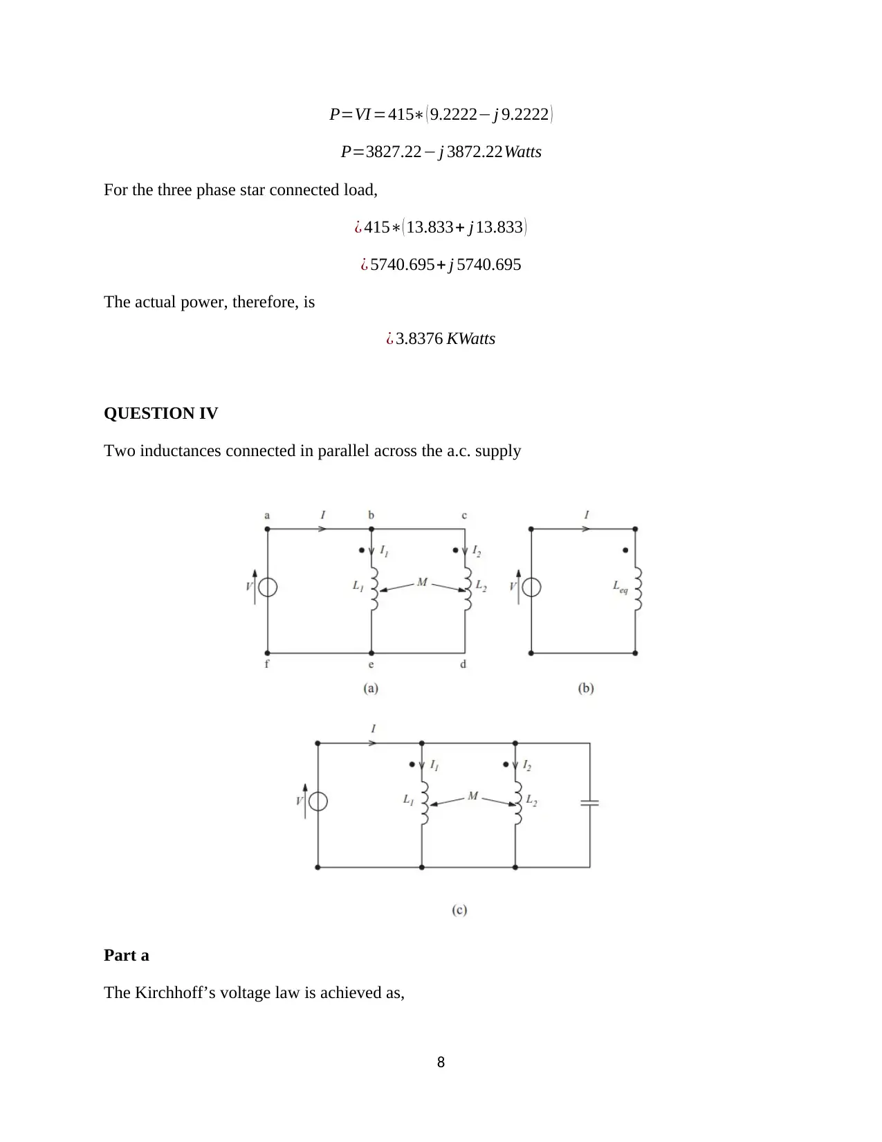
This document presents a solved assignment for an HNC Electrical Engineering course, focusing on electrical and electronic principles, specifically circuit theory. The assignment includes detailed solutions for various problems, such as determining current using Thevenin's theorem, superposition theorem, and Norton's theorem. It also covers mesh and nodal analysis for determining current in circuits, analysis of balanced three-phase loads (including delta and Y connections), and calculations for total power consumed. Furthermore, it addresses problems related to inductances connected in parallel and transformer voltage regulation, providing step-by-step calculations and explanations. The document is intended to help students understand and apply circuit theory concepts. Desklib provides access to a wealth of similar past papers and solved assignments.

HNC Electrical Engineering
Assignment
2019
MODULE TITLE: ELECTRICAL AND ELECTRONIC
PRINCIPLES
TOPIC TITLE: CIRCUIT THEORY
STUDENT NAME
ADDRESS
HOME TELEPHONE
EMPLOYER
WORK TELEPHONE
Assignment
2019
MODULE TITLE: ELECTRICAL AND ELECTRONIC
PRINCIPLES
TOPIC TITLE: CIRCUIT THEORY
STUDENT NAME
ADDRESS
HOME TELEPHONE
EMPLOYER
WORK TELEPHONE
Paraphrase This Document
Need a fresh take? Get an instant paraphrase of this document with our AI Paraphraser

1

QUESTION I
Determine current flowing in the load by
(i) Applying Thevenin’s theorem
(ii) Applying the superposition theorem
(iii) By transforming the two voltage sources and their associated reactance into current
sources (and thus form a pair of Norton generators)
Solution
Part a
The root mean square values are given as,
V 1=415 ∠ 900
V 2=415 ∠00=415
The load impedance,
ZL=50 ohms@ 0.7 pf
Converting into a polar representation,
2
⊘ This is a preview!⊘
Do you want full access?
Subscribe today to unlock all pages.

Trusted by 1+ million students worldwide

ZL=34.999+ j 35.707 ohms
Using Thevenin theorem, the circuit is divided into two loops,
loo p1 =− j 4 ( I1 )−35.002+ j35.705 ( I2 )=− j 415
loo p2 =− j 6 ( I 1 ) −35.002+ j 41.705 I 2=0
Part b
Implementing the Cramer’s rule,
¿ (− j 4 ) ( 35.002+ j 41.705 )− ( j 6 ) (−35.002+ j 35.705 )
¿ ( 166.82− j140.008 ) − ( 214.3+ j 210.012 )
¿−47.41− j 350.02
In the first loop, a matrix is obtained,
¿ [− j 415 −35.002+ j35.705
0 35.002+ j 41.705 ]
Removing the load the circuit is as illustrated below,
The load impedance is given as,
Z= √ R2+ X2
The power factor is given as 0.7 and the resistance is 50 ohms.
cos θ=0.7
arctan ( 51.01
50 )=45.57
Z=50+i 51.01
3
Paraphrase This Document
Need a fresh take? Get an instant paraphrase of this document with our AI Paraphraser

The load impedance is obtained as,
ZL=50 ∠ 45.570 ohms
Part c
Converting to current sources,
Zt = j 4∗j 6
j 4 + j 6
Zt =−24
j 10
Zt = j2.4
Therefore, the current is obtained as,
I = V 1−V 2
j4 + j6
The cosine value is shifted by 90 degrees such that,
V 2= √2∗425 cos ( 100 πt−900 )
Replacing in the current equation,
I =( √ 2∗425 cos ( 100 πt ) )−( √ 2∗425 cos ( 100 πt−900 ) )
j 4+ j 6
The load power factor is said to lag such that the load impedance is termed inductive. Solving the
equation above, the current is obtained as,
I = √ 2∗6.193 sin ( 100 πt+99.890 ) A
QUESTION II
Determining the current I in the circuit below by
(i) Mesh analysis
(ii) Nodal analysis
4

Solution
Part a
Using mesh analysis,
Loop 1:
V 1−Z1 I1−Z4 ( I1−I 2 )=0
V 1− ( Z1+ Z4 ) I 1+Z4 I 2=0
120− ( 2+ (− j 5 ) ) I1 + (− j5 ) I2=0
120− ( 2− j 5 ) I1− j5 I 2=0
120− ( 2− j 5 ) I1 + j5 I 2
Loop 3:
−V 2−Z5 ( I3−I2 )−Z3 I3=0
−V 2−Z5 I 2− ( Z3+Z5 ) I3 =0
− j120+ j 4 I2 − ( 4+ j 4 ) I3=0
− j120=− j 4 I2 + ( 4 + j 4 ) I 3
Part b
5
⊘ This is a preview!⊘
Do you want full access?
Subscribe today to unlock all pages.

Trusted by 1+ million students worldwide

While determining the nodal analysis,
V 10−V 20
Z1
+ 0−V 20
Z4
+ 0−V 30
Z5
+ V 40−V 30
Z3
+ V 20−V 30
Z2
=0
V 20−V 30
¿ 14.142+ j 14.142V
QUESTION III
For the balanced three-phase loads, determine
(i) The equivalent signal delta-connected load
(ii) The equivalent single Y-connected load obtained from the delta-star transformation
(iii) The equivalent single Y-connected load obtained by transforming the delta sub-loads
to a Y with the star-points of the two Y-sub circuits connected together.
(iv) The total power consumed above if the line voltage of the three phase supply is 415V
at 50 Hz.
6
Paraphrase This Document
Need a fresh take? Get an instant paraphrase of this document with our AI Paraphraser

Solution
Part a
¿ ( 45+ j 45 ) ( 45+ j45 )
90+ j 90
¿ 22.5+ j22.5 ohms
Part b
¿ ( 22.5+ j 22.5 ) ( 22.5+ j 22.5 )
( 22.5+ j 22.5 ) + ( 22.5+ j 22.5 ) + ( 22.5+ j22.5 )
¿ 7.5+ j7.5 ohms
Part c
The quotient is obtained from the ratio of the product to the sum of the impedance of the star
connection,
ZY = ( 15+ j 15 ) ( 15+ j 15 )
( 15+ j15 ) + ( 15+ j 15 )
ZY =7.5+ j 7.5 ohms
Part d
The total power is given as,
I = V
Z =−9.2222− j 9.2222 A
7

P=VI =415∗ ( 9.2222− j 9.2222 )
P=3827.22− j 3872.22Watts
For the three phase star connected load,
¿ 415∗( 13.833+ j13.833 )
¿ 5740.695+ j 5740.695
The actual power, therefore, is
¿ 3.8376 KWatts
QUESTION IV
Two inductances connected in parallel across the a.c. supply
Part a
The Kirchhoff’s voltage law is achieved as,
8
P=3827.22− j 3872.22Watts
For the three phase star connected load,
¿ 415∗( 13.833+ j13.833 )
¿ 5740.695+ j 5740.695
The actual power, therefore, is
¿ 3.8376 KWatts
QUESTION IV
Two inductances connected in parallel across the a.c. supply
Part a
The Kirchhoff’s voltage law is achieved as,
8
⊘ This is a preview!⊘
Do you want full access?
Subscribe today to unlock all pages.

Trusted by 1+ million students worldwide

ABEF ;V = jw L1 I1+ jwM I 2
ABCDEF ; v= jw L2 I 2 + jwM I 1
I 1= V∗( L2 −M )
jw∗( L1∗L2−M2
)
I 2= V∗( L1 −M )
jw∗( L1∗L2−M 2
)
Part b
I 1
I 2
= L2−M
L1−M
Leq=I1 + I 2
Part c
Leq=
( ( V∗ ( L2−M )
jw∗( L1∗L2−M 2 ) ) + (( V∗( L1−M )
jw∗( L1∗L2−M 2 ) ) ))
Admittance is given as,
Y = √ ( 1
R )2
+ ( ( 1
ωL )− ( ωC ) )2
The impedance of the circuit is obtained as,
Z= 1
Y = 1
√ ( 1
R )
2
+ (( 1
ωL )− ( ωC ) )
2
Part d
The capacitive reactance,
X c= 1
2 π √LC =f r Hz
The inductance reactance,
9
Paraphrase This Document
Need a fresh take? Get an instant paraphrase of this document with our AI Paraphraser

I = V
jwL
1
2 π √LC = 1
2 π √L∗1e-9
L=25.33 uH
The inductor and capacitor in a parallel connection provide the following admittance,
Y = 1
jω Leq
+ jωC
LT = L1 L2−M 2
L1 L2−2 M
LT =33.77 uH
QUESTION V
A 415V to 11 kV transformers has a rating of 200 kVA. The winding resistance and leakage
reactance when referred to the primary are 0.014 Ω and 0.057 Ω respectively.
Part a
The voltage regulation,
¿ 200e3
4152 ∗(0.014∗0.8+ 0.057∗√1−0.82 )∗100 %
¿ 5.27 %
Part b
Using the primary resistance from the secondary load resistance using turns ratio,
Rp =( 1
n )
2 Rl
Rp = 415
11e3 =0.037
The load resistance,
10

0.01= ( ( 425
11000 )
2
∗Rl )
Rl=7.026 ohms
The power factor is obtained
¿ 2e5
4152 ∗Rp∗100=0.017 ≈ 2 %
11
11000 )
2
∗Rl )
Rl=7.026 ohms
The power factor is obtained
¿ 2e5
4152 ∗Rp∗100=0.017 ≈ 2 %
11
⊘ This is a preview!⊘
Do you want full access?
Subscribe today to unlock all pages.

Trusted by 1+ million students worldwide
1 out of 12
Related Documents

Your All-in-One AI-Powered Toolkit for Academic Success.
+13062052269
info@desklib.com
Available 24*7 on WhatsApp / Email
Unlock your academic potential
Copyright © 2020–2025 A2Z Services. All Rights Reserved. Developed and managed by ZUCOL.