Mechanical Engineering Assignment: Gear, Coupling, and Flywheel
VerifiedAdded on 2023/04/21
|9
|1244
|56
Homework Assignment
AI Summary
This assignment solution addresses several key concepts in mechanical engineering. Task 1 analyzes a gear system, calculating angular velocities and the gear ratio, while also discussing common issues like gear erosion. Task 2 focuses on a jackscrew, determining efficiency and calculating effort required. Task 3 explores couplings, specifically universal joints, detailing their components and the speed variations they introduce, with an explanation of how to mitigate these variations. Finally, Task 4 delves into flywheel dynamics, calculating applied torque, stored energy, and the time it takes for a flywheel to stop, considering moment of inertia and friction.
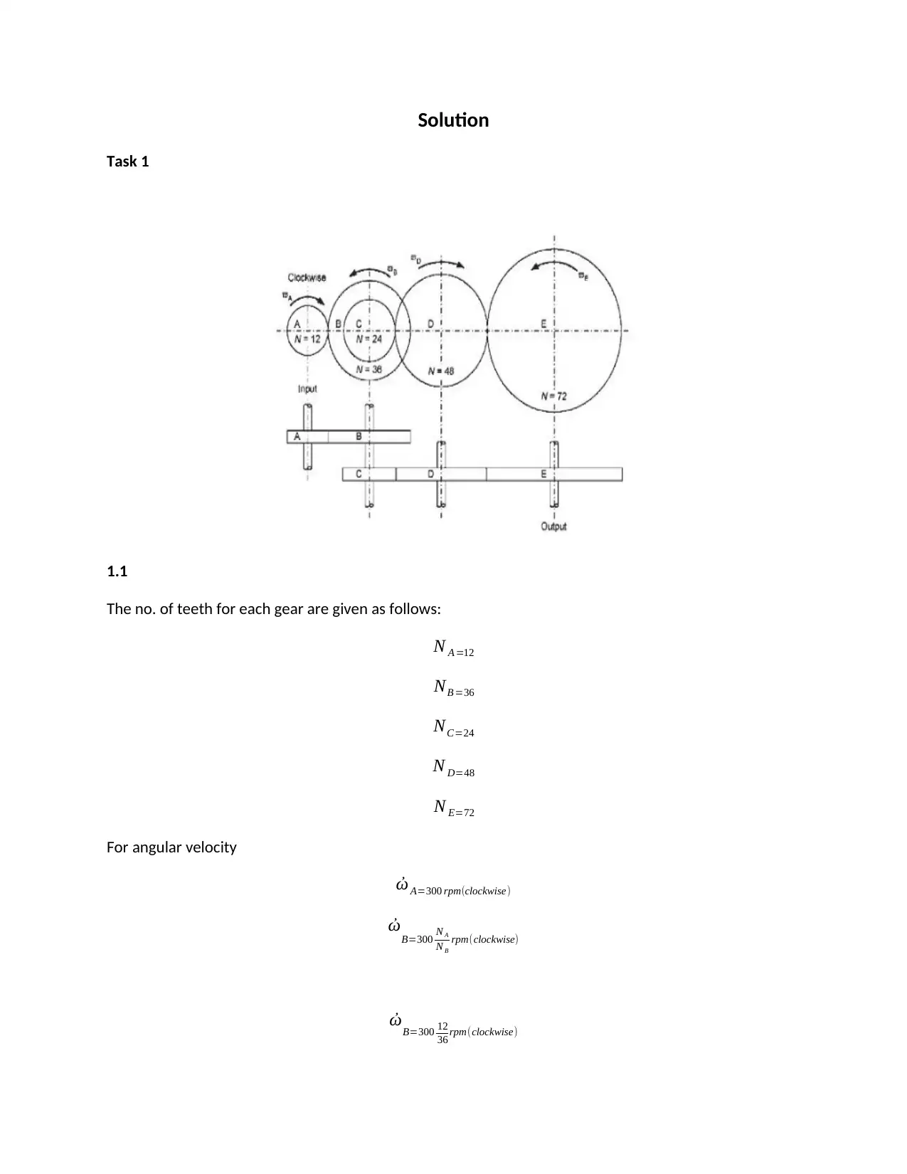
Solution
Task 1
1.1
The no. of teeth for each gear are given as follows:
N A =12
NB =36
NC=24
N D=48
N E=72
For angular velocity
ὠ A=300 rpm(clockwise)
ὠB=300 N A
N B
rpm(clockwise)
ὠB=300 12
36 rpm(clockwise)
Task 1
1.1
The no. of teeth for each gear are given as follows:
N A =12
NB =36
NC=24
N D=48
N E=72
For angular velocity
ὠ A=300 rpm(clockwise)
ὠB=300 N A
N B
rpm(clockwise)
ὠB=300 12
36 rpm(clockwise)
Paraphrase This Document
Need a fresh take? Get an instant paraphrase of this document with our AI Paraphraser
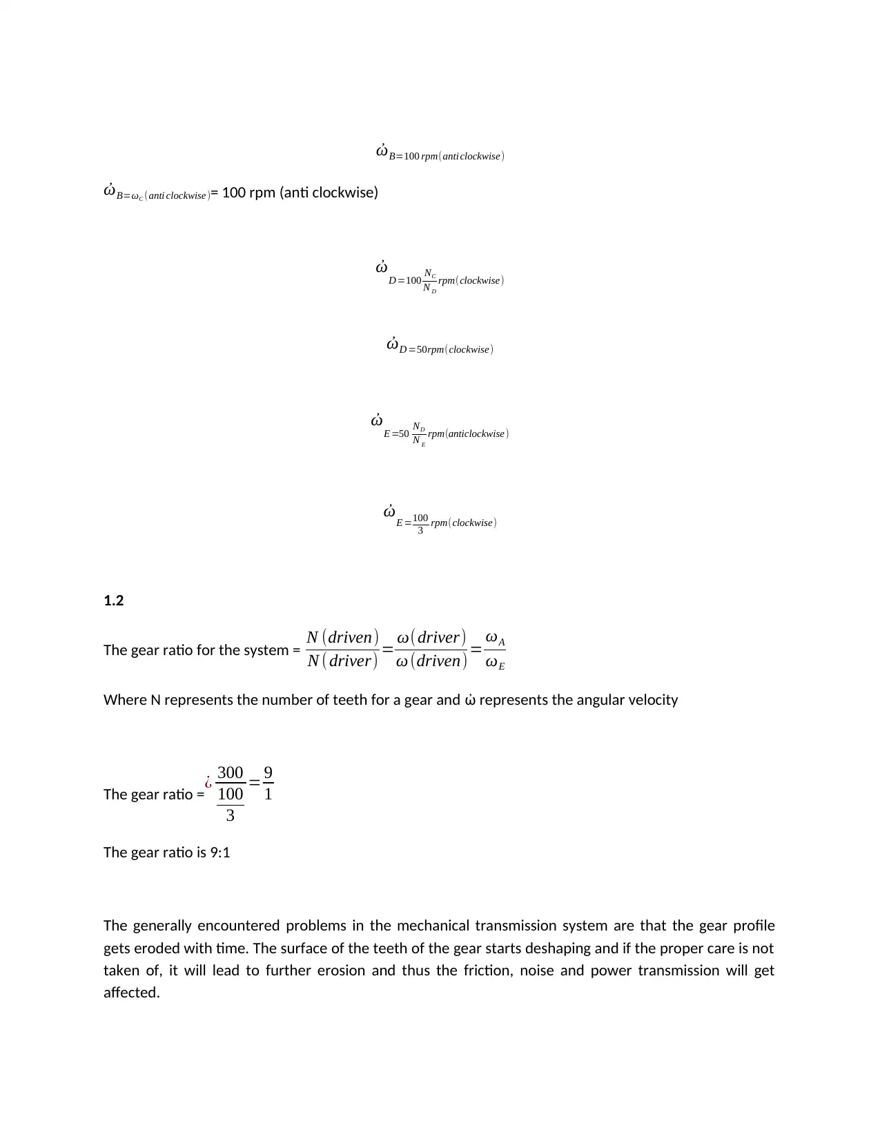
ὠB=100 rpm(anti clockwise)
ὠB=ωC (anti clockwise)= 100 rpm (anti clockwise)
ὠD =100 NC
N D
rpm(clockwise)
ὠD =50rpm(clockwise)
ὠE =50 ND
N E
rpm(anticlockwise)
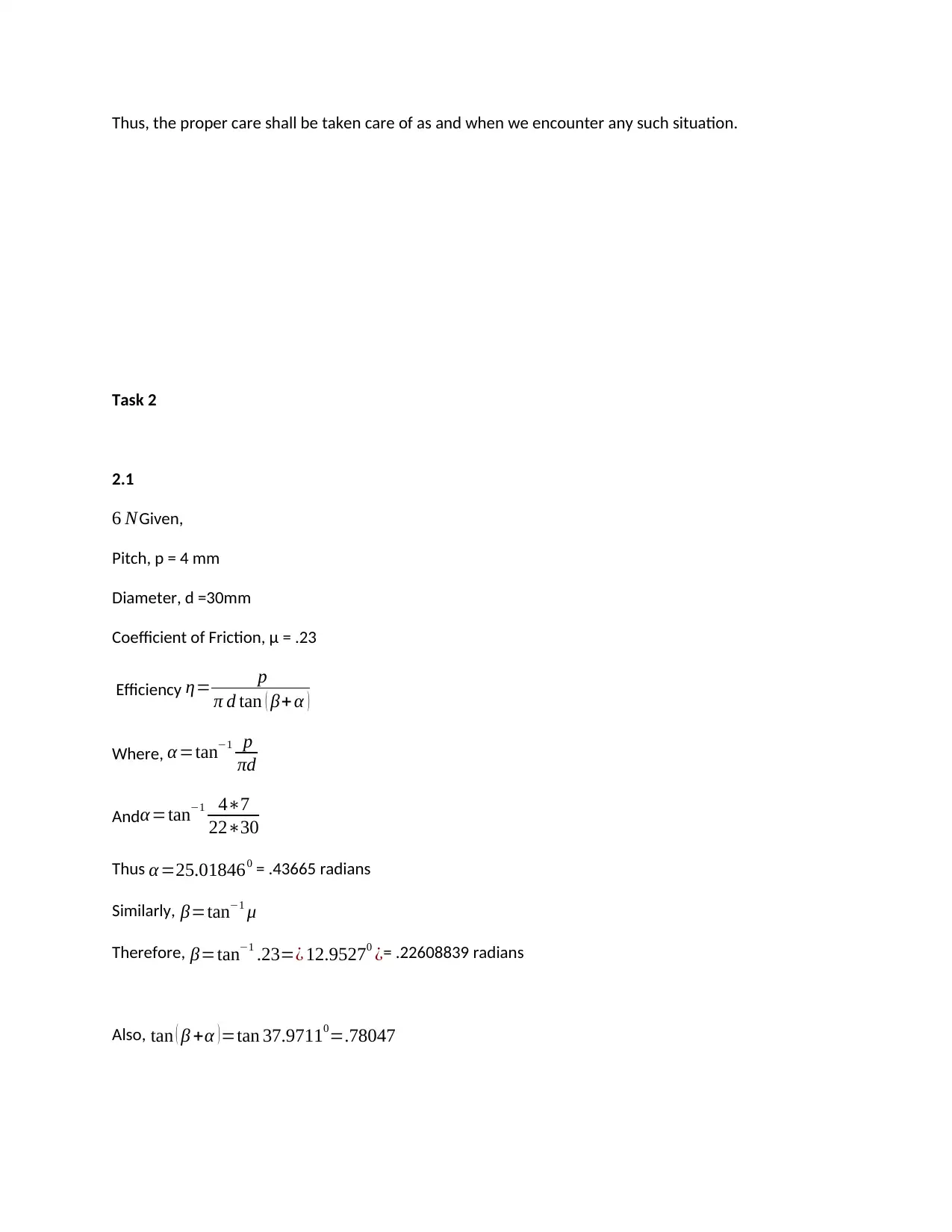
ὠE =100
3 rpm(clockwise)
1.2
The gear ratio for the system = N (driven)
N ( driver) = ω(driver)
ω (driven)= ωA
ωE
Where N represents the number of teeth for a gear and ὠ represents the angular velocity
The gear ratio = ¿ 300
100
3
= 9
1
The gear ratio is 9:1
The generally encountered problems in the mechanical transmission system are that the gear profile
gets eroded with time. The surface of the teeth of the gear starts deshaping and if the proper care is not
taken of, it will lead to further erosion and thus the friction, noise and power transmission will get
affected.
Thus, the proper care shall be taken care of as and when we encounter any such situation.
Task 2
2.1
6 NGiven,
Pitch, p = 4 mm
Diameter, d =30mm
Coefficient of Friction, μ = .23
Efficiency η= p
π d tan ( β+ α )
Where, α=tan−1 p
πd
Andα =tan−1 4∗7
22∗30
Thus α =25.018460 = .43665 radians
Similarly, β=tan−1 μ
Therefore, β=tan−1 .23=¿ 12.95270 ¿= .22608839 radians
Also, tan ( β +α )=tan 37.97110=.78047
⊘ This is a preview!⊘
Do you want full access?
Subscribe today to unlock all pages.

Trusted by 1+ million students worldwide
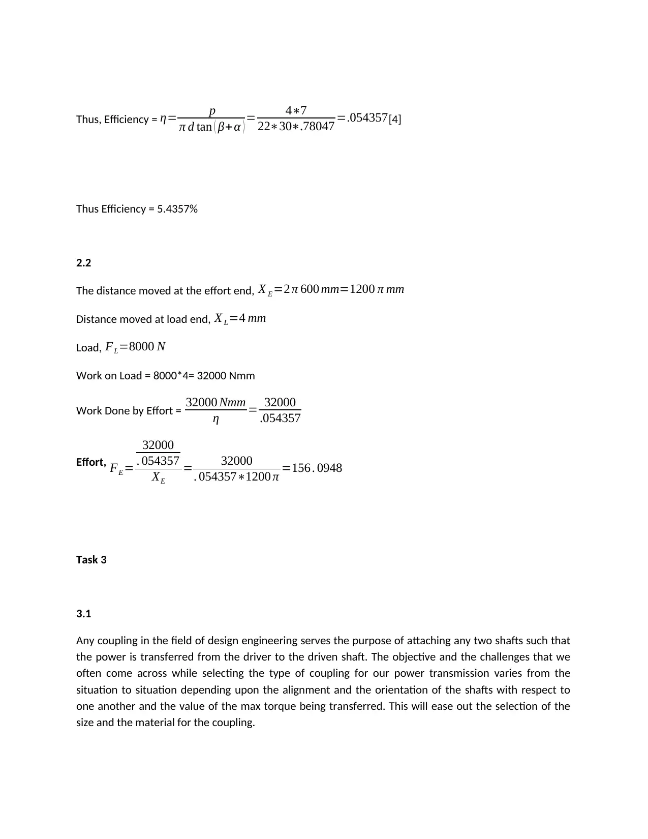
Thus, Efficiency = η= p
π d tan ( β+ α ) = 4∗7
22∗30∗.78047 =.054357[4]
Thus Efficiency = 5.4357%
2.2
The distance moved at the effort end, X E =2 π 600 mm=1200 π mm
Distance moved at load end, X L=4 mm
Load, FL=8000 N
Work on Load = 8000*4= 32000 Nmm
Work Done by Effort = 32000 Nmm
η = 32000
.054357
Effort, FE =
32000
. 054357
XE
= 32000
. 054357∗1200 π =156 . 0948
Task 3
3.1
Any coupling in the field of design engineering serves the purpose of attaching any two shafts such that
the power is transferred from the driver to the driven shaft. The objective and the challenges that we
often come across while selecting the type of coupling for our power transmission varies from the
situation to situation depending upon the alignment and the orientation of the shafts with respect to
one another and the value of the max torque being transferred. This will ease out the selection of the
size and the material for the coupling.
Paraphrase This Document
Need a fresh take? Get an instant paraphrase of this document with our AI Paraphraser
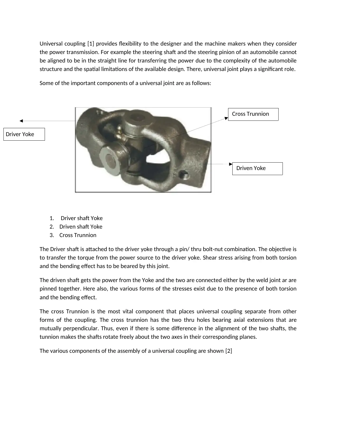
Universal coupling [1] provides flexibility to the designer and the machine makers when they consider
the power transmission. For example the steering shaft and the steering pinion of an automobile cannot
be aligned to be in the straight line for transferring the power due to the complexity of the automobile
structure and the spatial limitations of the available design. There, universal joint plays a significant role.
Some of the important components of a universal joint are as follows:
1. Driver shaft Yoke
2. Driven shaft Yoke
3. Cross Trunnion
The Driver shaft is attached to the driver yoke through a pin/ thru bolt-nut combination. The objective is
to transfer the torque from the power source to the driver yoke. Shear stress arising from both torsion
and the bending effect has to be beared by this joint.
The driven shaft gets the power from the Yoke and the two are connected either by the weld joint ar are
pinned together. Here also, the various forms of the stresses exist due to the presence of both torsion
and the bending effect.
The cross Trunnion is the most vital component that places universal coupling separate from other
forms of the coupling. The cross trunnion has the two thru holes bearing axial extensions that are
mutually perpendicular. Thus, even if there is some difference in the alignment of the two shafts, the
tunnion makes the shafts rotate freely about the two axes in their corresponding planes.
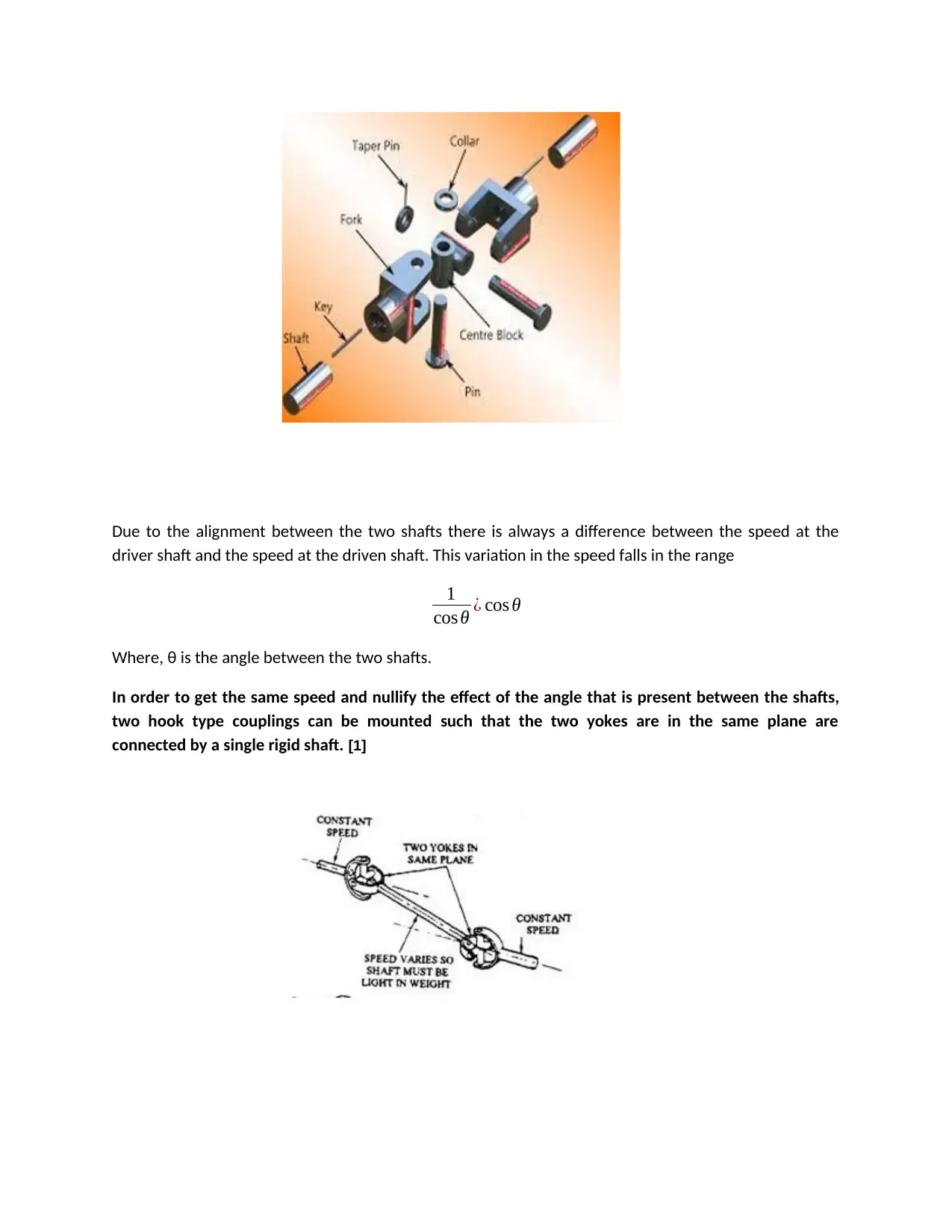
The various components of the assembly of a universal coupling are shown [2]
Cross Trunnion
Driven Yoke
Driver Yoke
Due to the alignment between the two shafts there is always a difference between the speed at the
driver shaft and the speed at the driven shaft. This variation in the speed falls in the range
1
cos θ ¿ cos θ
Where, θ is the angle between the two shafts.
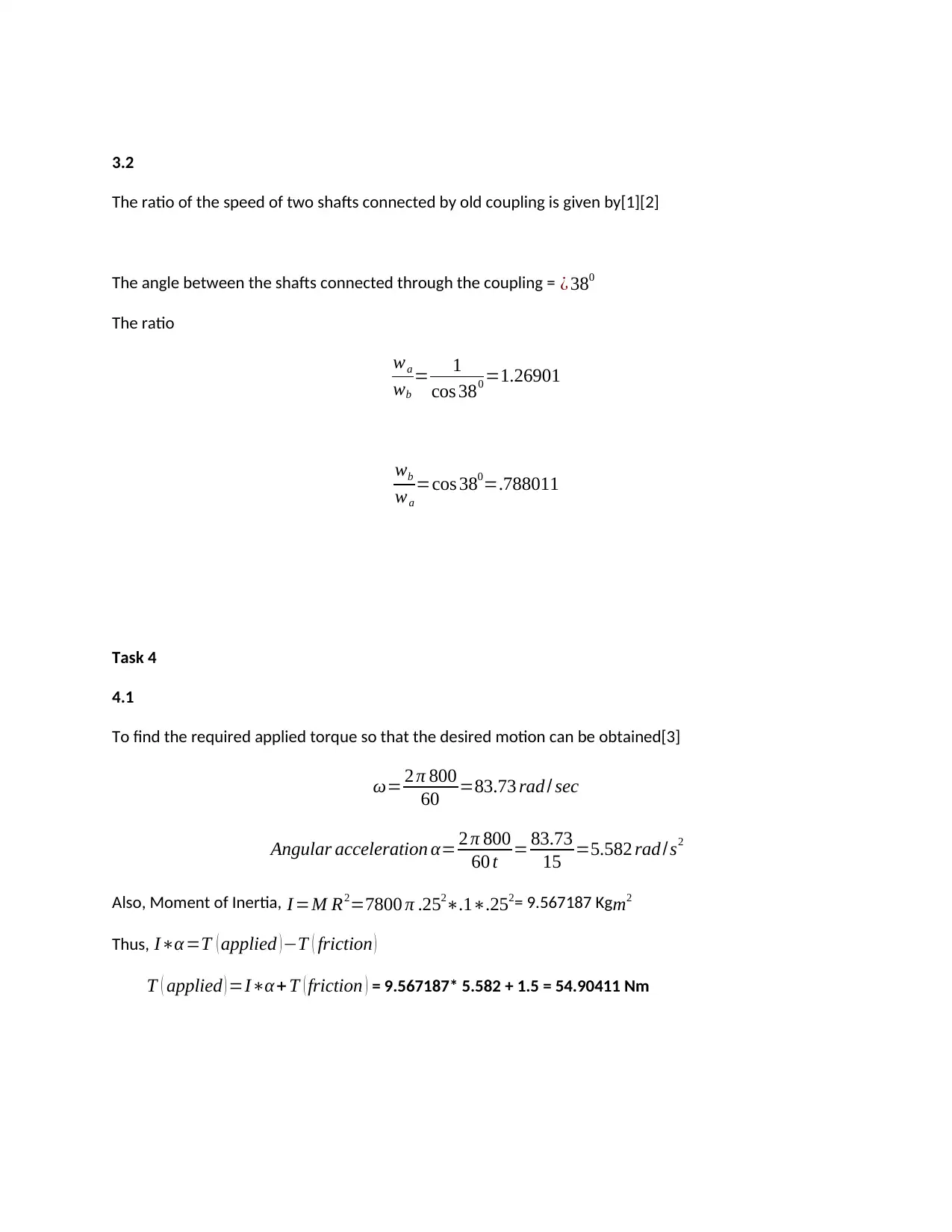
In order to get the same speed and nullify the effect of the angle that is present between the shafts,
two hook type couplings can be mounted such that the two yokes are in the same plane are
connected by a single rigid shaft. [1]
⊘ This is a preview!⊘
Do you want full access?
Subscribe today to unlock all pages.

Trusted by 1+ million students worldwide
3.2
The ratio of the speed of two shafts connected by old coupling is given by[1][2]
The angle between the shafts connected through the coupling = ¿ 380
The ratio
wa
wb
= 1
cos 380 =1.26901
wb
wa
=cos 380=.788011
Task 4
4.1
To find the required applied torque so that the desired motion can be obtained[3]
ω= 2 π 800
60 =83.73 rad / sec
Angular acceleration α= 2 π 800
60 t = 83.73
15 =5.582 rad /s2
Also, Moment of Inertia, I =M R2=7800 π .252∗.1∗.252= 9.567187 Kg m2
Thus, I∗α =T ( applied )−T ( friction )
T ( applied ) =I∗α+ T ( friction ) = 9.567187* 5.582 + 1.5 = 54.90411 Nm
Paraphrase This Document
Need a fresh take? Get an instant paraphrase of this document with our AI Paraphraser
4.2
Energy Stored = 1
2 I ω2= 1
2 9.567∗83.732
Energy Stored = 33535.74516 Joules
4.3
New moment of Inertia of the combined system, I = I(1) + I(2) = 2 * 9.567187 = 19.134374 Kg m2
Angular speed = 83.736 rad/sec
Angular deceleration due to friction = 2.2
19.134374 =.1149 rad
s2
Time taken to stop the Flywheel, t = 83 .73
.1149 =728 . 77 s
References
[1]"Universal Joints (Automobile)", What-when-how.com, 2019. [Online]. Available: http://what-when-
how.com/automobile/universal-joints-automobile/. [Accessed: 02- Jan- 2019].
[2]"Understanding Universal Joint - LearnEngineering", LearnEngineering, 2019. [Online]. Available:
https://learnengineering.org/understanding-universal-joint/index.html. [Accessed: 02- Jan- 2019].
[3]K. Gopinath and M. Mayuram, Flywheel, 1st ed. Chennai: IIT Madras, 2019, pp. 1-11.
[4]"Jackscrew", En.wikipedia.org, 2019. [Online]. Available: https://en.wikipedia.org/wiki/Jackscrew.
[Accessed: 02- Jan- 2019].
⊘ This is a preview!⊘
Do you want full access?
Subscribe today to unlock all pages.

Trusted by 1+ million students worldwide
1 out of 9
Your All-in-One AI-Powered Toolkit for Academic Success.
+13062052269
info@desklib.com
Available 24*7 on WhatsApp / Email
![[object Object]](/_next/static/media/star-bottom.7253800d.svg)
Unlock your academic potential
Copyright © 2020–2026 A2Z Services. All Rights Reserved. Developed and managed by ZUCOL.
