Southern Cross Tower: A Research Paper on High Rise Steel Framed Building
VerifiedAdded on 2023/06/04
|22
|5820
|428
AI Summary
This research project analyses the high rise Southern Cross tower building where the steel frame is used or where there is an important application of the structural steel networks. The southern cross tower which is also referred to as 121 Exhibition Street is a 530 feet (one hundred and sixty-one-metre skyscraper in Melbourne, Australia. the tower was constructed in the year 2004 and consisted of thirty-nine 39 levels of the accommodations offices. The building is about seventy-five per cent possessed by the multiplex trust property. The analysis of the displacement responses and the internal force with rare earthquakes have been carried out through the static elastic-plastic pushover analysis, and the common earthquakes have been carried out by the use of the method of static elastic time-history (Stern, 2014). This section also reviews the elastic-plastic and elastic structural process and methods
Contribute Materials
Your contribution can guide someone’s learning journey. Share your
documents today.
Southern Cross Tower 1
SOUTHERN CROSS TOWER
A Research Paper on High Rise Steel Framed Building By
Student’s Name
Name of the Professor
Institutional Affiliation
City/State
Year/Month/Day
SOUTHERN CROSS TOWER
A Research Paper on High Rise Steel Framed Building By
Student’s Name
Name of the Professor
Institutional Affiliation
City/State
Year/Month/Day
Secure Best Marks with AI Grader
Need help grading? Try our AI Grader for instant feedback on your assignments.
Southern Cross Tower 2
EXECUTIVE SUMMERY
This research project analyses the high rise Southern Cross tower building where the steel frame
is used or where there is an important application of the structural steel networks. The southern
cross tower which is also referred to as 121 Exhibition Street is a 530 feet (one hundred and
sixty-one-metre skyscraper in Melbourne, Australia. the tower was constructed in the year 2004
and consisted of thirty-nine 39 levels of the accommodations offices. The building is about
seventy-five per cent possessed by the multiplex trust property. The analysis of the displacement
responses and the internal force with rare earthquakes have been carried out through the static
elastic-plastic pushover analysis, and the common earthquakes have been carried out by the use
of the method of static elastic time-history (Stern, 2014). This section also reviews the elastic-
plastic and elastic structural process and methods
Southern Cross Tower 3
Table of Contents
EXECUTIVE SUMMERY.................................................................................................................................2
INTRODUCTION...........................................................................................................................................4
OVERVIEW OF THE STRUCTURE...................................................................................................................4
DESIGN DOCUMENTATION..........................................................................................................................5
SITE VISIT DOCUMENTATION......................................................................................................................6
STRUCTURAL SYSTEM..................................................................................................................................7
Foundation material building bearing strength and the site classification..............................................7
Footing system used................................................................................................................................8
Steel beams for roofs and floor system...................................................................................................9
Steel columns........................................................................................................................................11
Bracing members...................................................................................................................................12
Secondary structures.............................................................................................................................12
Design of truss chord.............................................................................................................................13
Composites materials............................................................................................................................14
LOADING ON THE STRUCTURE AND THE STRENGTH CALCULATION..........................................................15
Vertical Loads........................................................................................................................................15
Live loads...............................................................................................................................................17
Wind loads.............................................................................................................................................18
CONCLUSION.............................................................................................................................................19
BIBLIOGRAPHY...........................................................................................................................................20
Southern Cross Tower 4
INTRODUCTION
The steel frame is a building system with the skeleton edge of the vertical pillars of steels and
horizontal beam built in the rectangular grid to maintain the floor, roofs and walls of the house
all devoted to the frame. The expansion of this type of technique made the building of the
skyscraper promising. Prefabricated steel structure has some of the obvious advantages that are
quick construction, environmental protection and production in the industry. Even though the
prefabricated structure has been used in many countries in the world. In various occasions, these
structures are for the high and low rise buildings. This research project analyses the high rise
Southern Cross tower building where the steel frame is used or where there is an important
application of the structural steel networks.
OVERVIEW OF THE STRUCTURE
The southern cross tower which is also referred to as 121 Exhibition Street is a 530 feet (one
hundred and sixty-one-metre skyscraper in Melbourne, Australia. the tower was constructed in
the year 2004 and consisted of thirty-nine 39 levels of the accommodations offices. The building
is about seventy-five per cent possessed by the multiplex trust property and twenty-five per cent
is possessed by the multiplex prime acumen fund. The current value of the building is the A $one
hundred and thirty million and its main tenants are the state of Victorian Government (Acton,
n.d.).
Construction of the basement part up to the ground floor level adopted in-situ slabs and the band
beam. This gave more duration to in the program for the chosen steel parts procurement,
fabrication and delivery of the structural steel. The designers having the demonstrable experience
with the construction of steel had a good learning forwards the medium from the inception. At
Paraphrase This Document
Need a fresh take? Get an instant paraphrase of this document with our AI Paraphraser
Southern Cross Tower 5
times the prices of formworks increases and the climate of industries in the Melbourne favoured
the fabrication of site. The design exhibits the simplicity, typified by the regular grid, fifteen
meter clear spans on a sixteen by nine meters grid with the Gondek deck floor, allowing free
construction with the cycle of 8days per floor (Association, 2013).
The beam sizes were standardized using the 610UBs and 530.the slabs were normally one
hundred and twenty, thickened when important for the isolated weightier loadings. The
connection of the primary beams to the columns were the secondary beams and end bearings to
the core where the connection of web. The services were accommodated in the one-meter zone,
floor to floor height is four meters, applying the notches in some of the beams at the core
junction walls and some penetration of the web which were stiffened. The columns were
fabricated from the custom made four hundred and sixty section grades imported from Germany.
The enquiries from the design phase show that it was less expensive to import these sections,
there being more lead time. Splices were the full contract, situated one meter above the floor
with the three columns of storey lifts (Brannigan, 2012).
The engineering of fore was undertaken by Scott Lincoln adopted the spray of fire on the
columns up to the underside of primary beams for the passive protection. There were some of the
sprayings of fire of isolated beams trimmer. The system of curtain wall was fixed to the
structural steel by the welding using the sections of channels along the perimeter (Buckman,
2014).
DESIGN DOCUMENTATION
Before the growth of the Southern Cross, the government of Victoria was concerned since is the
main department were dispersed amongst more than fifteen offices through the Melbourne CBD.
It decided to combine monetarily and permit the bureaucracy access closer to the spring street,
Southern Cross Tower 6
providing it access to the treasury and parliament (Trabucco, 2010). A consortium of the private
bodies, comprising Babcock, multiplex and the Brown, recommended a skyscraper in the site of
the derelict and old south hotel. The main condition of the involvement of the government of
Victoria in the project was the mandate that the structure is a state of art, environmentally
maintainable growth (Buildings, 2015).
The major priority in the construction and design of the high-rise structures is to ensure their
inflexibility, steadiness and strength by taking into deliberations the effect of significant forces in
the wind overpowering the uneven shortening of vertical constructions from columns and walls
concrete reinforcement under the impact of the load. In Southern Cross Tower, the materials like
concrete and steel are majorly applied. The rigidity of the building skeleton assist in flexibility
and supporting the wind loads so as resist fluctuations is the seismic activities. In the facades of
the current skyscrapers, majorly polymers, aluminium, light curtain panels of darkened and
transparent glass, and steel profiles (Chung, 2013).
SITE VISIT DOCUMENTATION
We visited the site on 5th October 2018. The management received us and walked with us
around the site. Pomeroy pacific manages all the projects to ensure that the aims are delivered on
time, high quality and budget. They assign the calibre seniors to every project and give the
methodical and hand on the delivery approach which results in the reduced cost of the building,
quicker duration of the building, mitigated the project risks and successful completion of the
projects. We were showed the number of floors of the building, materials that were used to
construct the building. The field trip introduces us to the structural systems used in the Southern
Cross building and we were given the explanation how they support themselves as well as the
loads imposed on the building by the environment (Council, 2010).
Southern Cross Tower 7
STRUCTURAL SYSTEM
Foundation material building bearing strength and the site classification
The total area covered by the Southern Cross tower is around 17,338m2. The storeys above the
earth surface are applied as the apartments for the workers of board maintainable building
machinery limited. The structural life of the design of the south cross tower is fifty years. All the
components of Southern Cross tower were invented in the factory and moved to the location of
its building for the quick assembly by the use of S eight point eight grade bolts of great strength
of which the ultimate strength of tensile is 800MPa and yielding strength is six hundred and forty
MPa. The ratio of ultimate tensile strength to yielding strength 8.0. Compared with the old
strengthened concrete assemblies, the assembled steel structures have the evident benefits, that is
, they are very light in mass, need short duration of building, need low intensity of labour and
can meet the demands of great urbanization and gives the environmental protection at the same
time (Deplazes, 2010).
The south cross tower uses the new type of the prefabricated structures of steel known as the
modular produced high steel frame structures with the slanting braces which might be applied for
the high rise building. The pillar is prepared of a square steel tube, the beam us a truss and the
brace is prepared of C shaped steel prepared near the truss pillar joint, and the floor is a
summarized steel sheet composite concretes slabs (Thurakit, 2014). The structure has the benefit
of a manufactured structure of steel and the use of this assembly could attain the requirements of
environmental protection and economic growth in Australia. This method can help to consume
the extra manufacture of steel but could also assist to resolve the conflict among the limited land
and the huge population upon which to build in Australia (Eisele, 2015).
Secure Best Marks with AI Grader
Need help grading? Try our AI Grader for instant feedback on your assignments.
Southern Cross Tower 8
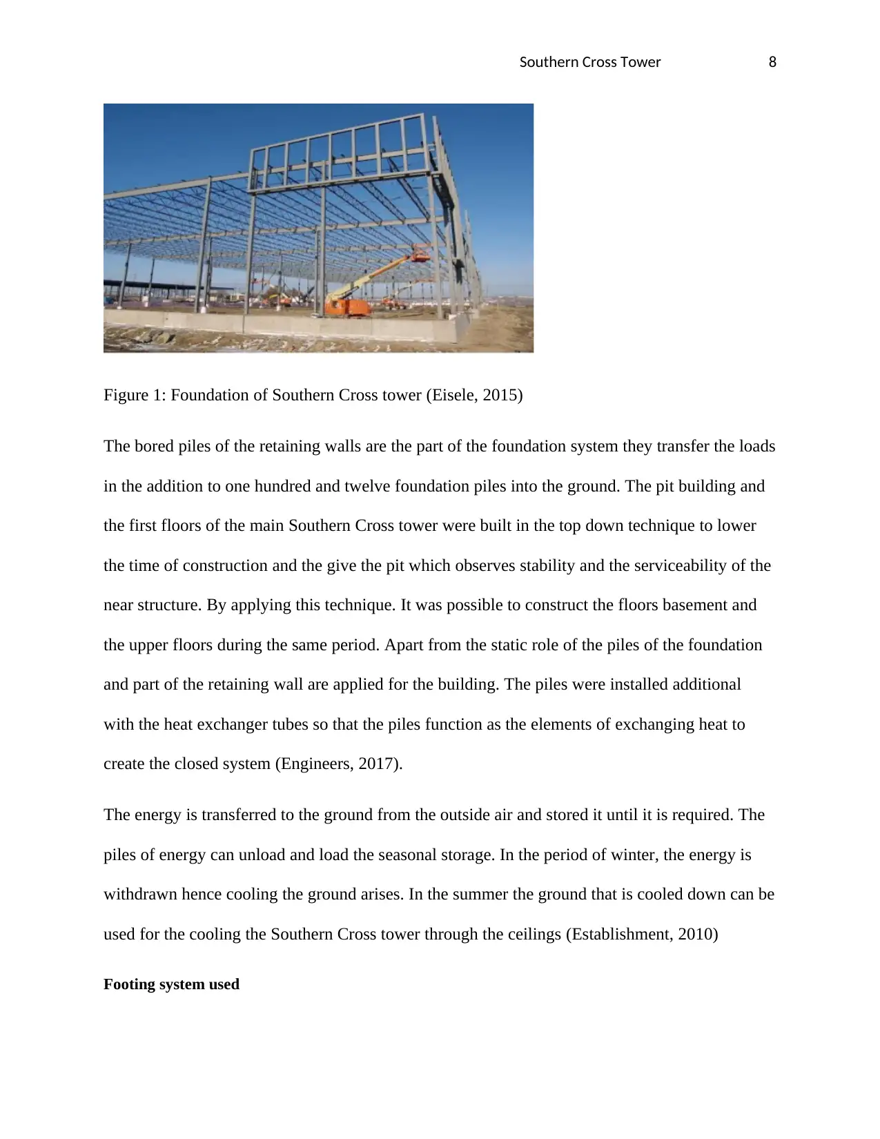
Figure 1: Foundation of Southern Cross tower (Eisele, 2015)
The bored piles of the retaining walls are the part of the foundation system they transfer the loads
in the addition to one hundred and twelve foundation piles into the ground. The pit building and
the first floors of the main Southern Cross tower were built in the top down technique to lower
the time of construction and the give the pit which observes stability and the serviceability of the
near structure. By applying this technique. It was possible to construct the floors basement and
the upper floors during the same period. Apart from the static role of the piles of the foundation
and part of the retaining wall are applied for the building. The piles were installed additional
with the heat exchanger tubes so that the piles function as the elements of exchanging heat to
create the closed system (Engineers, 2017).
The energy is transferred to the ground from the outside air and stored it until it is required. The
piles of energy can unload and load the seasonal storage. In the period of winter, the energy is
withdrawn hence cooling the ground arises. In the summer the ground that is cooled down can be
used for the cooling the Southern Cross tower through the ceilings (Establishment, 2010)
Footing system used
Southern Cross Tower 9
The process of construction of a fully prefabricated structure can be categorized into the
foundation, first-floor beam, floor and wall, roofing, and finishing. In the foundation stage. The
approaches involve the pouring of the foundation and hammering the concrete piles. This
approach cannot apply the prefabricated foundations due to the changes in the soil and site
leading to the process slowing. With the increase of the height of the Southern Cross building
increases the loads, the raft foundation was not good to transfer the loads well to the ground
hence the pile foundation was applied often. The major role of the pile foundation was to transfer
the loads with the piles to the lower ground level which is able of sustaining the load with
enough safety factor (Finnerty, 2013).
Figure2: How loads of the Southern Cross tower are being transferred to the earth (Goldsmith,
2015)
Steel beams for roofs and floor system
The next process is the roofing process where it is carried out by roofing structures from
prefabricated steel which need installation onsite. The prefabricated steel installation is a dry
Southern Cross Tower 10
process and only require to be joined by bolts hence there will be no time wastage as in the case
of the concrete roof structure process. The last process of construction of the prefabricated
buildings is the finishing which can take about 3 months after the construction process has taken
about 5 months for the residential structures. The process includes the doors and windows
installation which are also prefabricated units. Modular contractors manufacture structures at the
off-site location or in a factory. They may also work as projects contractors, finishing the
structure, site work, installation, and delivery coordination, or modular contractor whose
responsibilities are to installation, delivery, and construction of specifically the modules and the
general contractor whose is responsible for the whole project (Gong, 2010).
The modular manufactured steel frame structures with the diagonal braces are comprised of the 2
types of modules; the major floor and the pillar with the diagonal braces. The constituents inside
the similar modules are soldered in the factory and the bolts of great strength are applied to join
the module on the site. The major module of the floor comprises the column trusses, bases and
the concrete composite –steel sheet slabs. A truss is composed of the C shaped steel, angle steel,
arm braces, steel plates joined by the welding. Conferring to the action of every truss concerning
resistance of lateral loads, the trusses are grouped into secondary classes and girders. The arm
braces are welded vertically to the truss chords and are applied to join the upper and lower
diagonal braces (Habitat, 2011).
The floor system in the Southern Cross tower needs huge floor span to make superior space
elasticity for the accommodation of a better diversity of the floor span (Tatum, 2009). It is
important to decrease the weight of the floor so as to decrease the column size and the
foundations and hence allow the use of larger space. Floors are needed to resist the vertical loads
and they are normally supported by the secondary beam. The spacing of the supporting beams
Paraphrase This Document
Need a fresh take? Get an instant paraphrase of this document with our AI Paraphraser
Southern Cross Tower 11
must be well-matched with the resistance of the floor slabs. The floor system was made buildable
by the prefabricated or the precast elements of the steel and strengthened concrete in many
combinations. The system of floor beams must have enough stiffness to avoid large deflection
which could lead to the damage of the slab finishers and plaster (Hemsley, 2010).
Steel columns
The pillar base is made of the tube of square steel, plates and flanges. The bases of the column
cannot join to the transverse and longitudinal trusses and labs making the major module of the
floor but also join to the major floor unit with the lower and upper module on location to make
the entire structure. The major purpose of the diagonal braces is to minimize the operative
column dimension and concurrently to lengthen the joints and increase the joint region. Such a
structural scheme is known as a frame structure with strengthened joints which are considered
for security purposes (Hicks, 2015).
In the design of the steel columns, there are some of the things that were taken into
consideration. no part of the steel column was less than a quarter thick, no ,materials in the
column body and applied as the stay plate was of less thickness than 1/32 of its unsupported
width, measured between the rivets centre transversely, or 1/6 of the length between rivulet
centre in the stress direction (Taranath, 2016). The tie plates had more than 4 rivets and are to be
spaced so the length ratio to the least gyration radius of the joined parts did not exceed forty
(Huang, 2014).
Steel is a common metal of construction that was used in the building of the Southern Cross
tower because it has better performance in the withstanding of the tensile and compressive
forces. Steel bars were used to strengthen the concrete and to add the extra performance and the
extra layer of resisting fire was put onto the steel surface. The eight steel poles transmit the
Southern Cross Tower 12
structural loads and enable the formation of the floor area that is column free. It maximizes the
flexibility to adopt the different arrangements spatially (Huberman, 2011).
Bracing members
The pillar with the oblique braces comprises of the diagonal braces, column, and the trapezoid
plates known as the difficulty ribs. One end of the diagonal brace is joined via welding to the
pillar, where the additional end is joined to the arm brace and truss by the bolts to work together
with the frame. The rib of the pillar toughness can reinforce a pillar and be applied to join the
diagonal brace to the column. The diagonal braces have the lateral strong lateral stiffness
resistance which could make the construction capable to repel lateral load from the earthquakes
and wind. Since the surrounding area is very small the windows sizes and the door openings on
the walls are not interfered with (J, 2013).
The bracing system provides the lateral stability to the whole Southern Cross tower. It may be in
arrangement of the triangulated frames, shear cores or walls, and the inflexible articulated
frames. In the steel structures, it is very common to have the vertical truss that is triangulated to
deliver the bracing. For the stiff structure, the sheer core and walls are mostly used. The
efficiency of the Southern Cross tower to resist the lateral forces is dependents on the site and the
kinds of bracing systems used (Joseph, 2017).
Secondary structures
The purlins and girts are components of the second frame of the metal building. The girt is the
horizontal structural associate in the framed wall that gives the lateral support to the wall panel to
fight the wind loads. The purlins perform the similar service for the roof panel. The purlins and
girts are also referred to as the sheeting rails. These secondary frame members are applied in the
Southern Cross tower. Another secondary member, the strut is also known as the eave girt or the
Southern Cross Tower 13
eave purlin which are used at the top of the wall at the connection between the walls and the
roofs (Joshi, 2009).
The girder system includes the application of the shorter beam stubs which are soldered to the
top flange of an unremitting, weightier bottom girder structure and joined to the concrete slabs
via the application of shear studs (Strauss, 2012). The natural opening in the stub girder enables
the incorporation of the structural and service zones in the two directions, allowing the Southern
Cross tower’ elevation decrease when linked with other framing systems. The building has 2
tiers of the chamfered tenoned purlins and many wind braces. The central truss has been found to
be arch-braced collars trust connected in the post with extended jowls as the unusual technique
of framing in the area (Kastenbaum, 2012).
Design of truss chord
The diagonal strut which is the C designed steel is the member that is compressive flexure that
bears the force of axial and the bidirectional moments of bending. The brace is severely joined to
the chord of truss and the pillar at every end. The out and in-plane efficient dimension of the
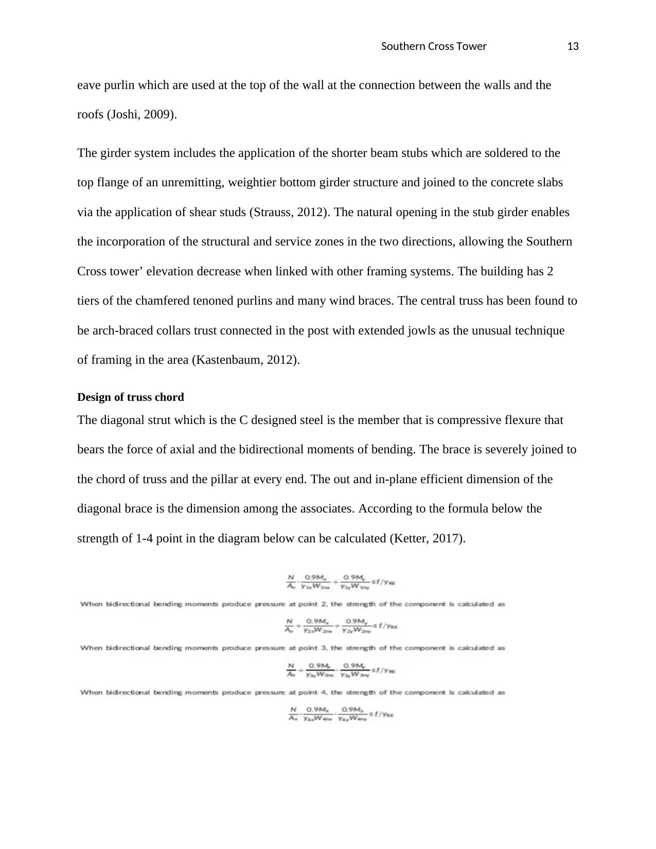
diagonal brace is the dimension among the associates. According to the formula below the
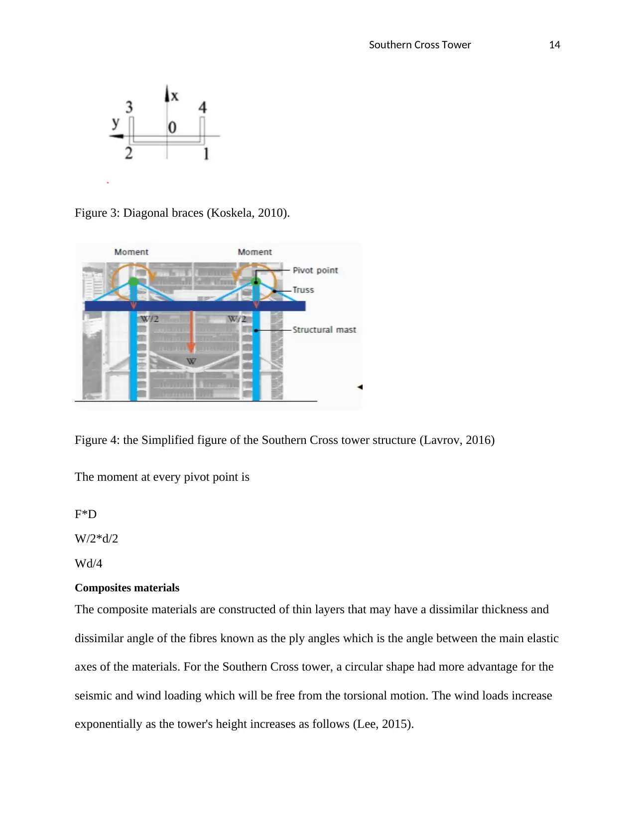
strength of 1-4 point in the diagram below can be calculated (Ketter, 2017).
Secure Best Marks with AI Grader
Need help grading? Try our AI Grader for instant feedback on your assignments.
Southern Cross Tower 14
Figure 3: Diagonal braces (Koskela, 2010).
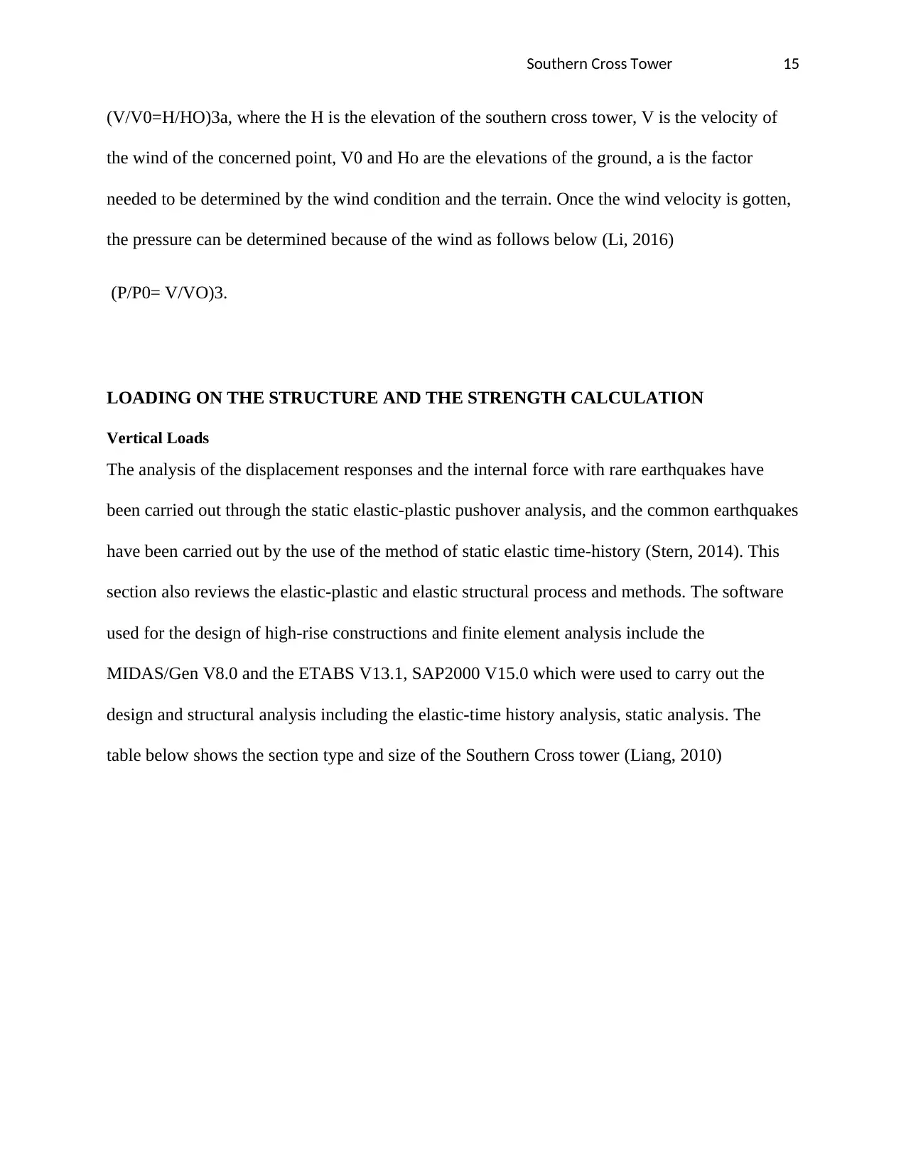
Figure 4: the Simplified figure of the Southern Cross tower structure (Lavrov, 2016)
The moment at every pivot point is
F*D
W/2*d/2
Wd/4
Composites materials
The composite materials are constructed of thin layers that may have a dissimilar thickness and
dissimilar angle of the fibres known as the ply angles which is the angle between the main elastic
axes of the materials. For the Southern Cross tower, a circular shape had more advantage for the
seismic and wind loading which will be free from the torsional motion. The wind loads increase
exponentially as the tower's height increases as follows (Lee, 2015).
Southern Cross Tower 15
(V/V0=H/HO)3a, where the H is the elevation of the southern cross tower, V is the velocity of
the wind of the concerned point, V0 and Ho are the elevations of the ground, a is the factor
needed to be determined by the wind condition and the terrain. Once the wind velocity is gotten,
the pressure can be determined because of the wind as follows below (Li, 2016)
(P/P0= V/VO)3.
LOADING ON THE STRUCTURE AND THE STRENGTH CALCULATION
Vertical Loads
The analysis of the displacement responses and the internal force with rare earthquakes have
been carried out through the static elastic-plastic pushover analysis, and the common earthquakes
have been carried out by the use of the method of static elastic time-history (Stern, 2014). This
section also reviews the elastic-plastic and elastic structural process and methods. The software
used for the design of high-rise constructions and finite element analysis include the
MIDAS/Gen V8.0 and the ETABS V13.1, SAP2000 V15.0 which were used to carry out the
design and structural analysis including the elastic-time history analysis, static analysis. The
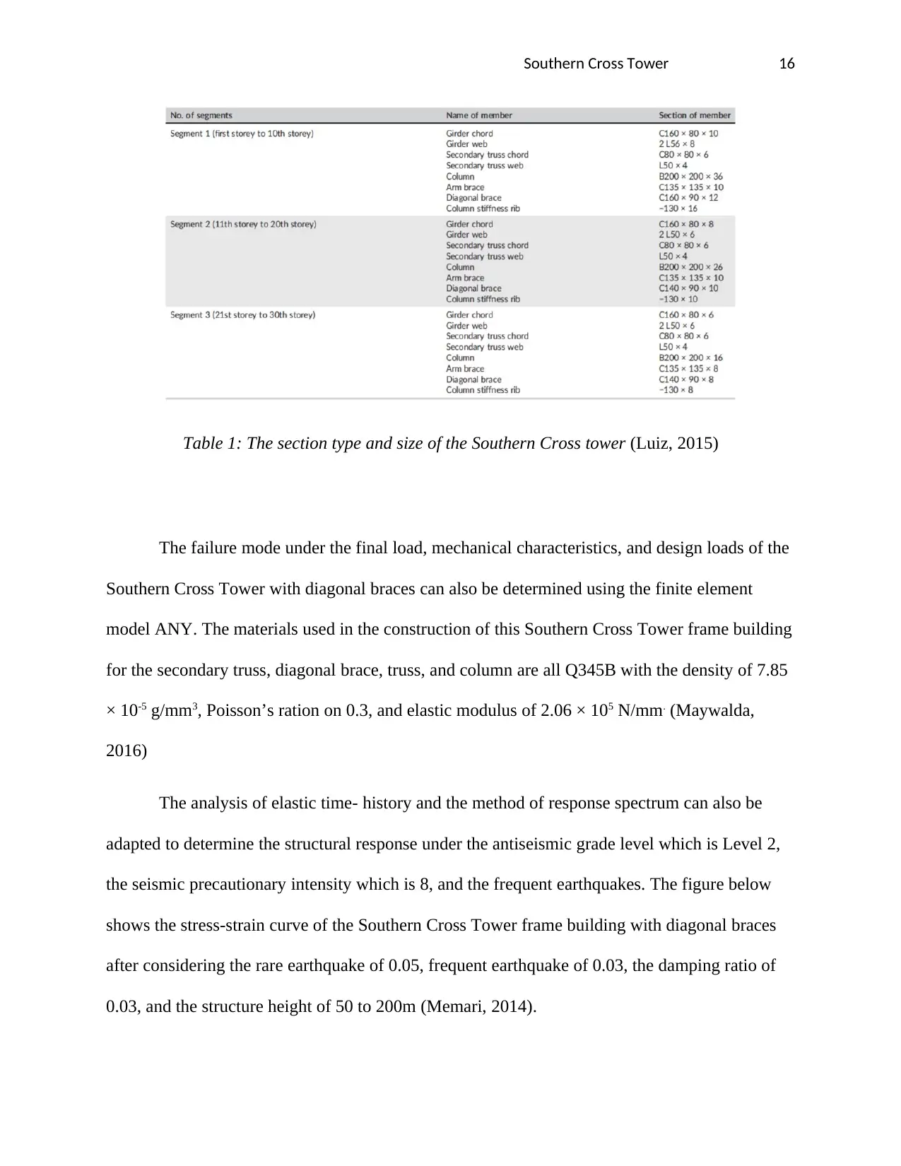
table below shows the section type and size of the Southern Cross tower (Liang, 2010)
Southern Cross Tower 16
Table 1: The section type and size of the Southern Cross tower (Luiz, 2015)
The failure mode under the final load, mechanical characteristics, and design loads of the
Southern Cross Tower with diagonal braces can also be determined using the finite element
model ANY. The materials used in the construction of this Southern Cross Tower frame building
for the secondary truss, diagonal brace, truss, and column are all Q345B with the density of 7.85
× 10-5 g/mm3, Poisson’s ration on 0.3, and elastic modulus of 2.06 × 10⁵ N/mm. (Maywalda,
2016)
The analysis of elastic time- history and the method of response spectrum can also be
adapted to determine the structural response under the antiseismic grade level which is Level 2,
the seismic precautionary intensity which is 8, and the frequent earthquakes. The figure below
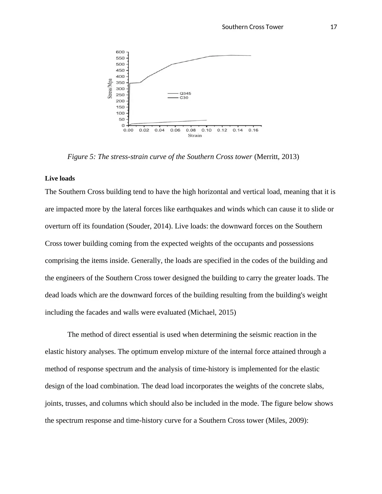
shows the stress-strain curve of the Southern Cross Tower frame building with diagonal braces
after considering the rare earthquake of 0.05, frequent earthquake of 0.03, the damping ratio of
0.03, and the structure height of 50 to 200m (Memari, 2014).
Paraphrase This Document
Need a fresh take? Get an instant paraphrase of this document with our AI Paraphraser
Southern Cross Tower 17
Figure 5: The stress-strain curve of the Southern Cross tower (Merritt, 2013)
Live loads
The Southern Cross building tend to have the high horizontal and vertical load, meaning that it is
are impacted more by the lateral forces like earthquakes and winds which can cause it to slide or
overturn off its foundation (Souder, 2014). Live loads: the downward forces on the Southern
Cross tower building coming from the expected weights of the occupants and possessions
comprising the items inside. Generally, the loads are specified in the codes of the building and
the engineers of the Southern Cross tower designed the building to carry the greater loads. The
dead loads which are the downward forces of the building resulting from the building's weight
including the facades and walls were evaluated (Michael, 2015)
The method of direct essential is used when determining the seismic reaction in the
elastic history analyses. The optimum envelop mixture of the internal force attained through a
method of response spectrum and the analysis of time-history is implemented for the elastic
design of the load combination. The dead load incorporates the weights of the concrete slabs,
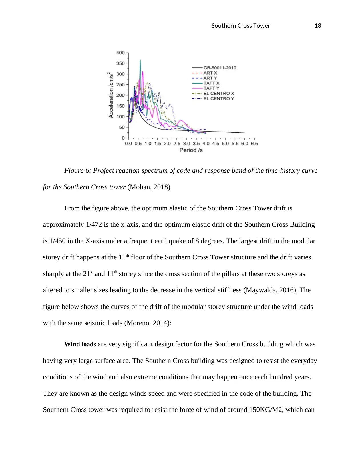
joints, trusses, and columns which should also be included in the mode. The figure below shows
the spectrum response and time-history curve for a Southern Cross tower (Miles, 2009):
Southern Cross Tower 18
Figure 6: Project reaction spectrum of code and response band of the time-history curve
for the Southern Cross tower (Mohan, 2018)
From the figure above, the optimum elastic of the Southern Cross Tower drift is
approximately 1/472 is the x-axis, and the optimum elastic drift of the Southern Cross Building
is 1/450 in the X-axis under a frequent earthquake of 8 degrees. The largest drift in the modular
storey drift happens at the 11th floor of the Southern Cross Tower structure and the drift varies
sharply at the 21st and 11th storey since the cross section of the pillars at these two storeys as
altered to smaller sizes leading to the decrease in the vertical stiffness (Maywalda, 2016). The
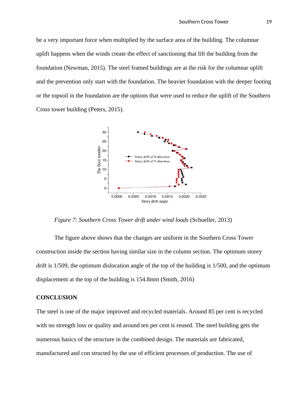
figure below shows the curves of the drift of the modular storey structure under the wind loads
with the same seismic loads (Moreno, 2014):
Wind loads are very significant design factor for the Southern Cross building which was
having very large surface area. The Southern Cross building was designed to resist the everyday
conditions of the wind and also extreme conditions that may happen once each hundred years.
They are known as the design winds speed and were specified in the code of the building. The
Southern Cross tower was required to resist the force of wind of around 150KG/M2, which can
Southern Cross Tower 19
be a very important force when multiplied by the surface area of the building. The columnar
uplift happens when the winds create the effect of sanctioning that lift the building from the
foundation (Newman, 2015). The steel framed buildings are at the risk for the columnar uplift
and the prevention only start with the foundation. The heavier foundation with the deeper footing
or the topsoil in the foundation are the options that were used to reduce the uplift of the Southern
Cross tower building (Peters, 2015).
Figure 7: Southern Cross Tower drift under wind loads (Schueller, 2013)
The figure above shows that the changes are uniform in the Southern Cross Tower
construction inside the section having similar size in the column section. The optimum storey
drift is 1/509, the optimum dislocation angle of the top of the building is 1/500, and the optimum
displacement at the top of the building is 154.8mm (Smith, 2016)
CONCLUSION
The steel is one of the major improved and recycled materials. Around 85 per cent is recycled
with no strength loss or quality and around ten per cent is reused. The steel building gets the
numerous basics of the structure in the combined design. The materials are fabricated,
manufactured and con structed by the use of efficient processes of production. The use of
Secure Best Marks with AI Grader
Need help grading? Try our AI Grader for instant feedback on your assignments.
Southern Cross Tower 20
materials is optimized highly in the Southern Cross tower and the wastes eliminated virtually.
The steel construction gives the low investment prices. Optimum cost of operation, and the
outstanding flexibility if the southern tower use with high-quality id he aesthetic, functionality
and fast times of construction. The high proportion of the offsite fabrication in the southern
tower building means that the conditions and controlled, safer and protected from the weather.
BIBLIOGRAPHY
Acton, .. A., n.d. Issues in Structural and Materials Engineering. Michigan2012: ScholarlyEditions.
Association, B. C. S., 2013. Historical Structural Steelwork Handbook. California: British Constructional
Steelwork Association.
Brannigan, F., 2012. Building Construction for the Fire Services. Toledo: Jones & Bartlett Learning.
Buckman, W., 2014. Under the Southern Cross Tower. Michigan: Book publishers' Press.
Buildings, T., 2015. Construction of Tall Buildings. Melbourne: Routledge.
Chung, K., 2013. Advances in Steel Structure. Toledo: Elsevier.
Council, I. C., 2010. International Building Codes. New York: International Code Council.
Deplazes, A., 2010. Constructing Architecture: Materials, Processes, Structures. Chicago: Springer Science
& Business Media.
Eisele, J., 2015. High-rise Manual: Typology and Design, Construction and Technology. Colorado:
Birkhäuser-Publishers for Architecture.
Southern Cross Tower 21
Engineers, A. S. o. C., 2017. Minimum Design Loads for Buildings and Other Structures. Sydney: American
Society of Civil Engineers.
Establishment, B. R., 2010. Wind and snow loading. Sydney: Construction Press.
Finnerty, A., 2013. The Architecture of East Australia: An. Tasmania: Edition Axel Menges.
Goldsmith, M., 2015. Technique and aesthetics in the design of tall buildings. New York: Institute for the
Study of the High-Rise Habitat.
Gong, Z., 2010. A Quantitative Approach to the Assessment of the Environmental Impact of Building
Materials. Beijing: Management Science and Engineering.
Habitat, C. o. T. B. a. U., 2011. Structural design, codes, and special building projects. New York: Council
on Tall Buildings and Urban Habitat.
Hemsley, J., 2010. Design Applications of Raft Foundations. Michigan: Thomas Telford.
Hicks, S., 2015. Comparative structure cost of modern commercial buildings. Paris: Steel Construction
Institute.
Huang, D., 2014. Advanced Engineering and Technology. Hong Kong: CRC Press.
Huberman, 2011. A life-cycle energy analysis of building materials in Australia. Beijing: Energy Build.
Joseph, L., 2017. Outrigger Design for High-Rise Buildings. Sydney: CRC Press.
Joshi, S., 2009. Product environmental life-cycle assessment using input-output techniques. Perth: J. Ind.
Ecol.
J, P., 2013. Structures and Architecture. Colorado: CRC Press.
Kastenbaum, S., 2012. Modular Construction: The Future of High-Rise Building. Toledo: from
thinkwingradio.com.
Ketter, R., 2017. Structural analysis and design. Paris: McGraw-Hill.
Koskela, L., 2010. The Foundations of Lean Construction.” Design and Construction: Building in Value, R.
Best, and G. de Valence, eds., Butterworth-Heinemann. Oxford: Elsevier.
Lavrov, P., 2016. High-rise buildings: an erroneous vector of housing construction. Michigan: Bulletin of
Civil Engineers.
Lee, R., 2015. Building Maintenance Management. New York: Wiley.
Liang, Q. Q., 2010. Performance-Based Optimization of Structures. Perth: CRC Press.
Li, G.-Q., 2016. Advanced Analysis and Design of Steel Frames. Paris: John Wiley & Sons.
Luiz, F., 2015. Modern Architecture. Toledo: University of Texas Press.
Maywalda, C., 2016. Sustainability – The Art of Modern Architecture. Perth: Procedia Engineering.
Memari, 2014. Residential and Commercial Building Construction. Mumbai: J. Archit. Eng.
Southern Cross Tower 22
Merritt, F., 2013. Building Design and Construction Handbook, Perth: McGraw Hill Professional.
Michael, D., 2015. Skyscraper rivals. Michigan: Princeton Architectural Press.
Miles, M., 2009. Real Estate Development: Principles and Process. Washington D.C.: Urban Land
Institute.
Mohan, R., 2018. Recent Advances in Structural Engineering. Melbourne: Springer.
Moreno, J., 2014. Analysis and Design of High-Rise Concrete Buildings. New York: American Concrete
Institute.
Newman, A., 2015. Steel Building Systems Design and Specifications. Colorado: McGraw Hill Professional.
Peters, R., 2015. Framing Basics. California: Sterling Publishing Company.
Schueller, W., 2013. The vertical building structure. Toledo: Van Nostrand Reinhold.
Smith, B. S., 2016. Tall building structures: analysis and design. Michigan: Wiley.
Souder, C., 2014. Temporary Structure Design. Perth: John Wiley & Sons.
Stern, A. H., 2014. Southern Cross Tower. Victoria: University of Alabama Press.
Strauss, A., 2012. Life-Cycle and Sustainability of Civil Infrastructure Systems. Colorado: CRC Press.
Taranath, B., 2016. Tall Building Design: Steel, Concrete, and Composite Systems. chicago: CRC Press.
Tatum, C., 2009. Constructability improvement using prefabrication, preassembly, and modularization.
Texas: Bureau of Engineering Research, University of Texas.
Thurakit, K., 2014. Thailand Real Estate News. Thailand:
http://www.manager.co.th/daily/viewnews.aspx?NewsID=9560000100604.
Trabucco, D., 2010. Damping Technologies for Tall Buildings: Theory, Design Guidance and Case Studies.
Paris: Elsevier Science.
1 out of 22
Related Documents
Your All-in-One AI-Powered Toolkit for Academic Success.
+13062052269
info@desklib.com
Available 24*7 on WhatsApp / Email
Unlock your academic potential
© 2024 | Zucol Services PVT LTD | All rights reserved.