Spectrum Analyzer Project - Analyzing Modulated Signals and Time Domain Measurements
VerifiedAdded on 2021/06/11
|6
|1228
|185
AI Summary
Spectrum analyzers are tools used to measure the periodic waveform spectrum. Learn about the working of spectrum analyzers, ways to analyze modulated signals, measurements of noise and time domain, and sensitivity. Get detailed insights on the subject and course code if mentioned, course name if mentioned, and college/university if mentioned.
Contribute Materials
Your contribution can guide someone’s learning journey. Share your
documents today.

Spectrum analyzer project
Secure Best Marks with AI Grader
Need help grading? Try our AI Grader for instant feedback on your assignments.
Analyzer of spectrum
Spectrum analyzers are tools used to measure the periodic waveform spectrum. A super
heterodyne receptor is the most frequent form of spectrum analyzer. A Fast Fourier Transform
(FFT) spectrum analyzer is another sort of spectrum analyzer that is becoming popular.
Spectrum analyzers are used to indicate in the frequency domain the frequency and amplitude of
the signals. Efficient information transmission is achieved by a process called as modulation.
This approach changes the normally low frequency information transmission to a higher
frequency by the use of a third, modulating signal. But why do the original signal modulate? The
first two arguments are:
(1) modulation methods enable simultaneous transmission to a higher frequency and carrier of
two or more low frequency or base band signals.
2) Small physical-size high-frequency antennas are more electrically efficient. In this section,
three common modulation formats are considered:
• Modulation of amplitude or AM.
• Modulation of frequency or FM.
• Modulation of the pulses or PM.
Spectrum Analyzer Work
The difference frequency is really the frequency of interest in a spectrum analyzer. The mixer
changed our RF input to an IF (Intermediate Frequency) signals, which can now be filtered,
amplified and detected by the analyzer to show the signal on the screen.
Ways to analyses modulated signal
The spectrum analyzer output is an X-Y track on the display, so let's examine what information
we obtain from that. The display is mapped to a grid with 10 main horizontal divisions and 10
main vertical divisions in general. In frequency that goes from left to right, the horizontal axis is
linearly calibrated. Frequency setting is a two-step procedure. We first alter the centerline
frequency of the graph using the center frequency slider. Then we modify the frequency range
(range) throughout the 10 divisions by controlling the frequency range. These settings are
separate, so we don't change the frequency range if we change the central frequency.
Alternatively, instead of selecting center frequency, we may specify the start and stop
frequencies. In each situation, the absolute frequency of each signal presented and the relative
frequency difference between any two signals may be determined.
The following details have been provided for FM calculations
i-e
Frequency = 35.14 MHz
Strip width = 10 kHz
Module = DRM
When there is an interfering system, the quantity of interfering power must be known. The
system may function correctly or not depending on the interfering power level. In addition, if the
level of interference power is high enough to reduce the quality of the system under
investigation, knowledge of the amount of interference is important in order to develop a suitable
solution. In the spectrum assigned to the DRM service (Digital Radio Mondiale).
A spectrum analyzer consists of multiple procedures which adjust the fluctuations in envelope-
detected amplitude.
The 3 ways are utilised here
Measurements of noise
Provide optimal analyzer performance for detecting phase noise:
If a signal's phase sound is assessed using a spectrum analyzer, ensure that the local oscillator's
noise level in the spectrum analyzer is about 6 dB greater than the expected signal under test. If
not, the spectrum analyzer phase noise will damage the result. If the extreme circumstance is
better than the spectrum analyzer's local oscillator, the spectrum analyzer's phase-noise is
assessed.
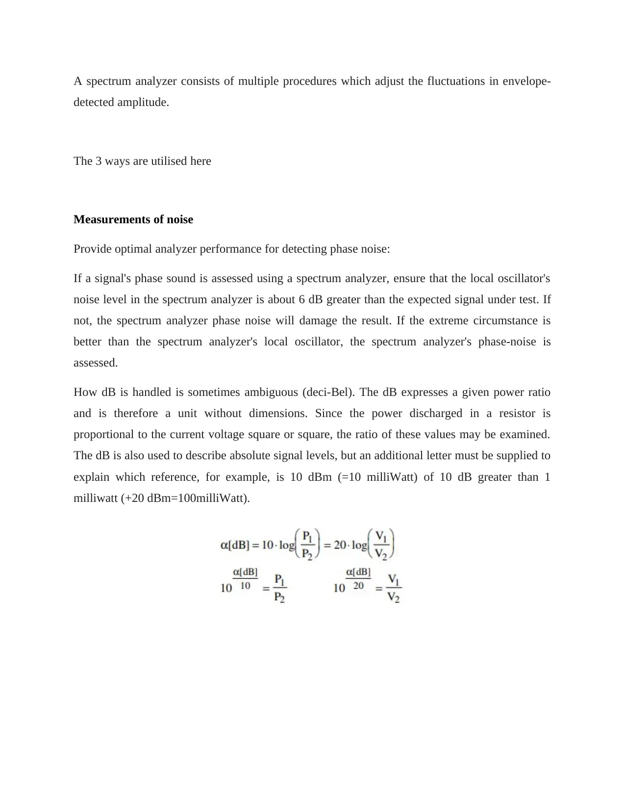
How dB is handled is sometimes ambiguous (deci-Bel). The dB expresses a given power ratio
and is therefore a unit without dimensions. Since the power discharged in a resistor is
proportional to the current voltage square or square, the ratio of these values may be examined.
The dB is also used to describe absolute signal levels, but an additional letter must be supplied to
explain which reference, for example, is 10 dBm (=10 milliWatt) of 10 dB greater than 1
milliwatt (+20 dBm=100milliWatt).
Secure Best Marks with AI Grader
Need help grading? Try our AI Grader for instant feedback on your assignments.
Measurements of the time domain
Using the Vector Network Analyzer Time Domain option, "low pass" or "band-pass" mode is
offered. The low pass mode can only be utilised for equidistant sampling in the frequency field
(equidistant to DC), since the Fourier Transform generates a line spectrum with equidistant line
distance, including frequency zero. This shows that the instrument must first determine the
correct frequency for low-pass mode for a specified frequency range and data points (done by
using the soft-key: set frequency Low-pass). Calibration may be done after predetermined
frequency. For a linear time-invariant system, frequency and time domain measurements
(excluding signal-to-noise) are almost equivalent and may be translated together by the Fourier
transformation.
The Fourier transforms a spectrum with consistent density throughout a given frequency range
(rectangular spectrum). This feature displays undesirable "side lollipops" and hence applies
weighting [=window] in the frequency domain before entering FFT. This weighting function is
generally Gaussian or sin2 and may be used to significantly minimise side lobes in temporal
field. Use the pulse and step function in low-pass mode. The step function is just part of the pulse
response. Gating is not a linear technique when using the gating function, hence gating may
introduce bogus frequency components that are not present before gating. The spectral lines
(frequency domain data points) need not be equidistant to DC in band pass mode, but just in the
interface frequency. For the same bandwidth, the comparable time domain response is twice
longer than in low-pass mode, and we frequently have intricate time domain signals. In complex
mixer terminology, these difficult signals are similar to the I and Q signals (I=in phase and
Q=square). Use "real" or "imaginary" soft-keys to show them immediately in the format menu.
The true component is what you perceive at a fast range, i.e. a Gaussian envelope RF signal. The
phrase band-pass response in linear magnitude notation is "modulus of a carrier's complex
envelope modulated signal. Note that time domain mode may also be used to VNA CW
excitation, but then analyse a DUT response that slows down time variations (up to the IF
bandwidth of 3 KHz).
Sensitivity
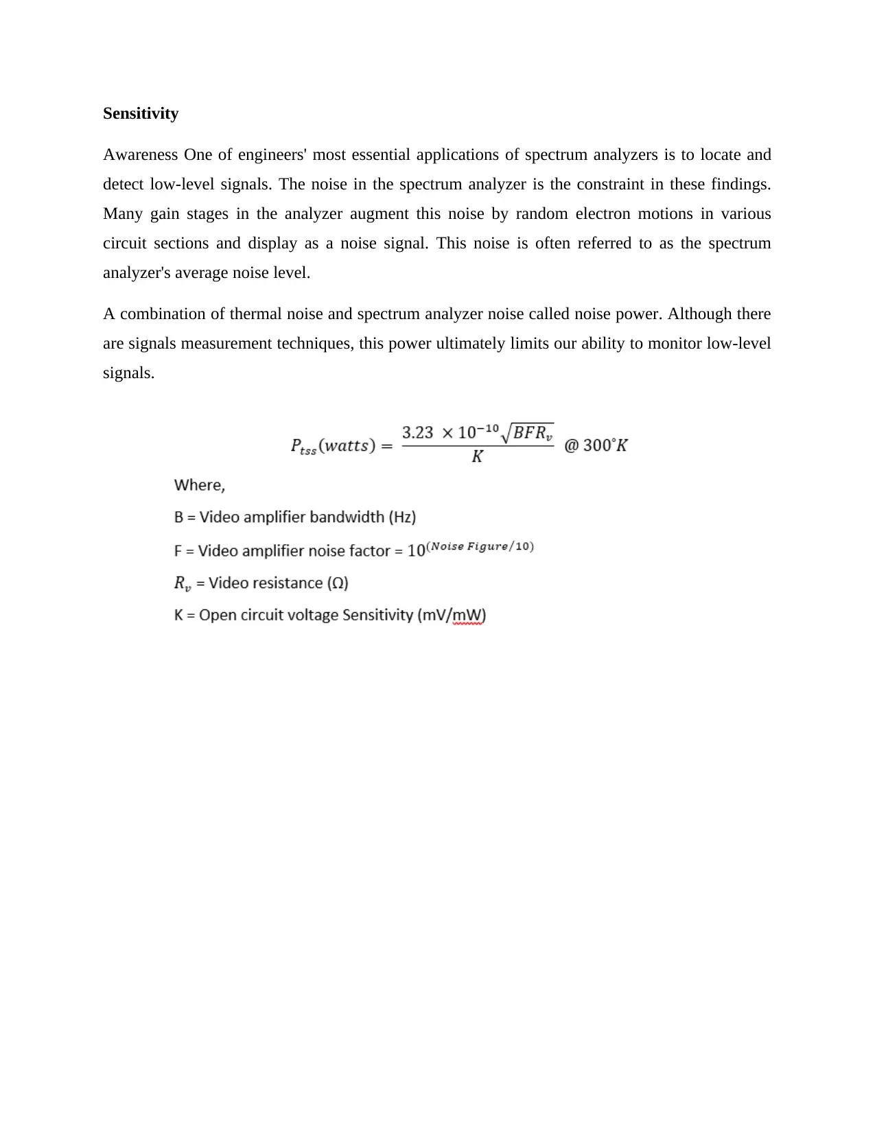
Awareness One of engineers' most essential applications of spectrum analyzers is to locate and
detect low-level signals. The noise in the spectrum analyzer is the constraint in these findings.
Many gain stages in the analyzer augment this noise by random electron motions in various
circuit sections and display as a noise signal. This noise is often referred to as the spectrum
analyzer's average noise level.
A combination of thermal noise and spectrum analyzer noise called noise power. Although there
are signals measurement techniques, this power ultimately limits our ability to monitor low-level
signals.
1 out of 6
Your All-in-One AI-Powered Toolkit for Academic Success.
+13062052269
info@desklib.com
Available 24*7 on WhatsApp / Email
![[object Object]](/_next/static/media/star-bottom.7253800d.svg)
Unlock your academic potential
© 2024 | Zucol Services PVT LTD | All rights reserved.
