Design and Fabrication of Square Ring Microstrip Patch Antenna for RADAR
VerifiedAdded on 2023/06/04
|9
|1695
|99
AI Summary
This project involves designing, integrating, fabricating and implementing Square Ring Microstrip Patch Antennas for RADAR. It also includes researching and studying the total effect of the antenna dimensions and variation of the substrate materials on the bandwidth. The project was completed by a team of engineers, with the Senior Electronics Engineer responsible for proposing the design and executing the simulation using CST Microwave Studio. The Network Analyzer was used for testing the microstrip patch antenna. The project aimed to provide a compact design of the square ring microstrip patch antenna with a resonant frequency of 6 GHz for RADAR.
Contribute Materials
Your contribution can guide someone’s learning journey. Share your
documents today.
CE 3.1 Project Information
Name of the project: Design and Fabrication of Square Ring Microstrip Patch
Antenna
Location of the project: Please fill
Project Duration: Please fill
Organization: Please fill
Role and Designation during the time: Senior Electronics Engineer
CE 3.2 Project Background
CE 3.2.1 Characteristics of the project
Microstrip antennas are such antennas that are fabricated with the help of microstrip
technique on PCB. These microstrip antennas are utilized at the microwave frequencies. In
this project, I have designed as well as fabricated the square ring microstrip patch antennas. I
have provided this design of the square ring microstrip antenna, which is optimal for
RADAR. During the project, I have used the increase in bandwidth and gain of the microstrip
patch, operating at 6.0GHz. I even had to study the entire effect of the antenna dimensions as
well as variation of substrate materials on the bandwidth. Since, the frequency operation of
the microstrip antenna is between 2GHz and 11GHz, I have done the project for Worldwide
Interoperability for Microwave Access (RADAR). Moreover, I have also used CST
microwave studio for this 3D EM simulation of the high frequency elements. I have even
utilized the Network Analyzer for testing my project of the respective square ring microstrip
patch antenna.
Secure Best Marks with AI Grader
Need help grading? Try our AI Grader for instant feedback on your assignments.
CE 3.2.2 Objectives developed for the project
This project of the Design as well as Fabrication of Square Ring Microstrip Patch
Antenna was completed to properly design, integrate as well as implement the Square Ring
Microstrip Patch Antenna. I have used the specified resonant frequency of this microstrip
patch antenna of 6GHz for RADAR. Hence, for completing this project and providing better
efficiency and effectiveness, few objectives were developed by me and these are provided
below:
To design, integrate, fabricate and implement these Square Ring Microstrip Patch
Antennas.
To execute the project of microstrip patch antennas that operates at the resonance
frequency of 6 GHz for Worldwide Interoperability for Microwave Access (RADAR).
To research and study the total effect of the antenna dimensions and variation of the
substrate materials on the bandwidth.
To use CST microwave studio as one of the major tools for the 3D EM simulation of
the high frequency elements.
To test and analyze this particular square ring micro strip patch antenna with the help
of Network Analyzer.
To compare and contrast my obtained results with the previous theoretical researches.
CE 3.2.3 My area of work
I was hired as the Senior Electronics Engineer within the project. As I had enough
experience, I could easily propose a design for my microstrip patch antenna. Being one of the
responsible team members, I was able to execute my duties and responsibilities within the
project successfully. I had even better idea of CST microwave studio and hence this 3D EM
simulation of the higher frequency elements. I was also assigned for solving the various
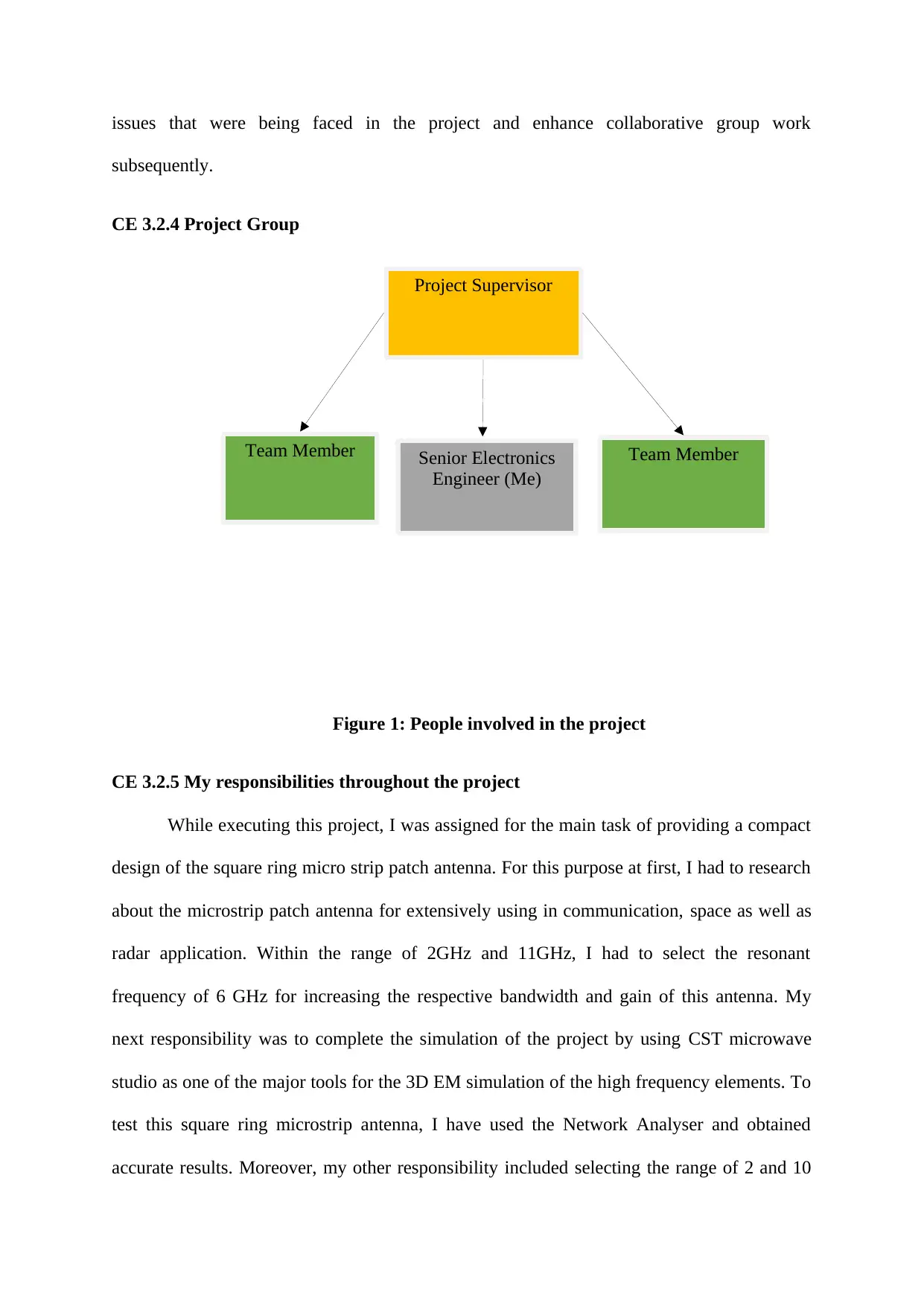
Project Supervisor
Team Member Senior Electronics
Engineer (Me)
Team Member
issues that were being faced in the project and enhance collaborative group work
subsequently.
CE 3.2.4 Project Group
Figure 1: People involved in the project
CE 3.2.5 My responsibilities throughout the project
While executing this project, I was assigned for the main task of providing a compact
design of the square ring micro strip patch antenna. For this purpose at first, I had to research
about the microstrip patch antenna for extensively using in communication, space as well as
radar application. Within the range of 2GHz and 11GHz, I had to select the resonant
frequency of 6 GHz for increasing the respective bandwidth and gain of this antenna. My
next responsibility was to complete the simulation of the project by using CST microwave
studio as one of the major tools for the 3D EM simulation of the high frequency elements. To
test this square ring microstrip antenna, I have used the Network Analyser and obtained
accurate results. Moreover, my other responsibility included selecting the range of 2 and 10
on the basis of radar application. I have also used several algorithms for calculation of the
inner and outer edges.
CE 3.3 Distinctive Activity
CE 3.3.1 Comprehending the Theory of Project
For the designing of square ring, I increased the slot of narrow width that is embedded
into the ground plane. For the core purpose of computing the radiation pattern of square ring
antenna, I calculated the Lθ and Lϕ separately from inner and outer edges. Moreover, the
microstrip line feeding technique, I connected the conducting strip to the edge of their
microstrip patch. For avoiding the higher impedance of 50 ohm, I have used sections of
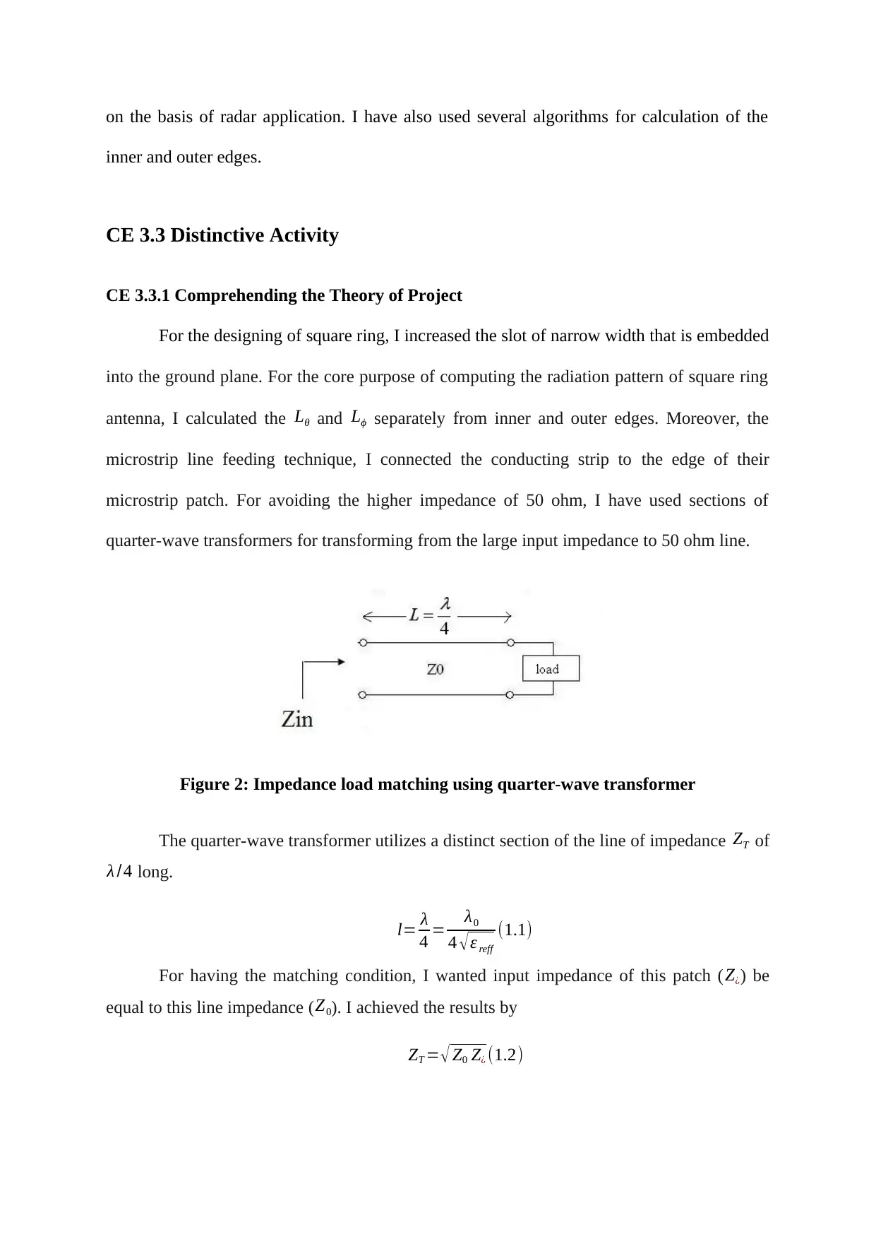
quarter-wave transformers for transforming from the large input impedance to 50 ohm line.
Figure 2: Impedance load matching using quarter-wave transformer
The quarter-wave transformer utilizes a distinct section of the line of impedance ZT of
λ /4 long.
l= λ
4 = λ0
4 √ ε reff
(1.1)
For having the matching condition, I wanted input impedance of this patch (Z¿) be
equal to this line impedance (Z0). I achieved the results by
ZT = √ Z0 Z¿ (1.2)
Paraphrase This Document
Need a fresh take? Get an instant paraphrase of this document with our AI Paraphraser
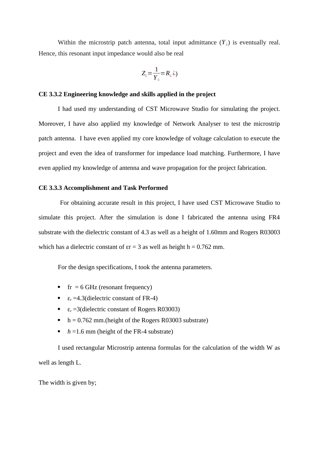
Within the microstrip patch antenna, total input admittance (Y ¿) is eventually real.
Hence, this resonant input impedance would also be real
Z¿= 1
Y ¿
=R¿ ¿)
CE 3.3.2 Engineering knowledge and skills applied in the project
I had used my understanding of CST Microwave Studio for simulating the project.
Moreover, I have also applied my knowledge of Network Analyser to test the microstrip
patch antenna. I have even applied my core knowledge of voltage calculation to execute the
project and even the idea of transformer for impedance load matching. Furthermore, I have
even applied my knowledge of antenna and wave propagation for the project fabrication.
CE 3.3.3 Accomplishment and Task Performed
For obtaining accurate result in this project, I have used CST Microwave Studio to
simulate this project. After the simulation is done I fabricated the antenna using FR4
substrate with the dielectric constant of 4.3 as well as a height of 1.60mm and Rogers R03003
which has a dielectric constant of εr = 3 as well as height h = 0.762 mm.
For the design specifications, I took the antenna parameters.
fr = 6 GHz (resonant frequency)
εr =4.3(dielectric constant of FR-4)
εr =3(dielectric constant of Rogers R03003)
h = 0.762 mm.(height of the Rogers R03003 substrate)
h =1.6 mm (height of the FR-4 substrate)
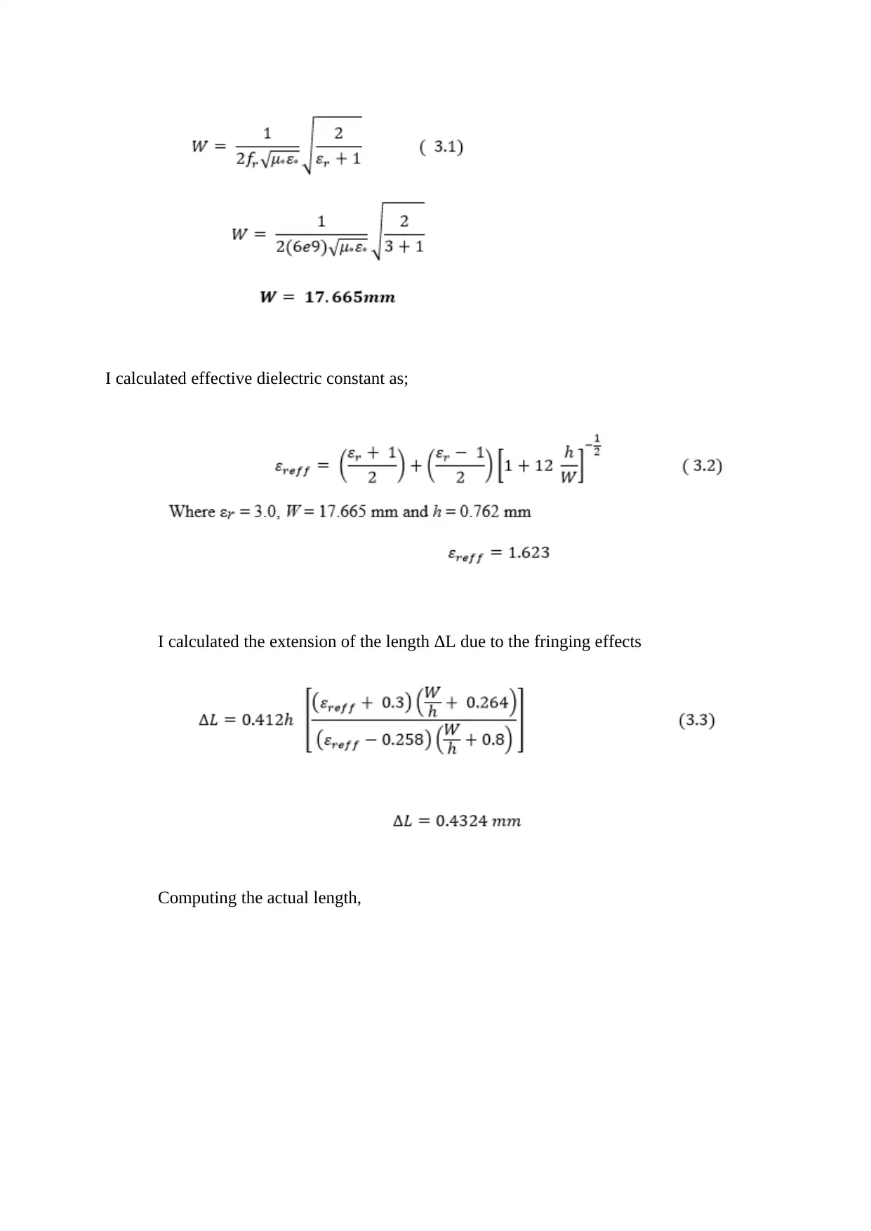
I used rectangular Microstrip antenna formulas for the calculation of the width W as
well as length L.
The width is given by;
I calculated effective dielectric constant as;
I calculated the extension of the length ΔL due to the fringing effects
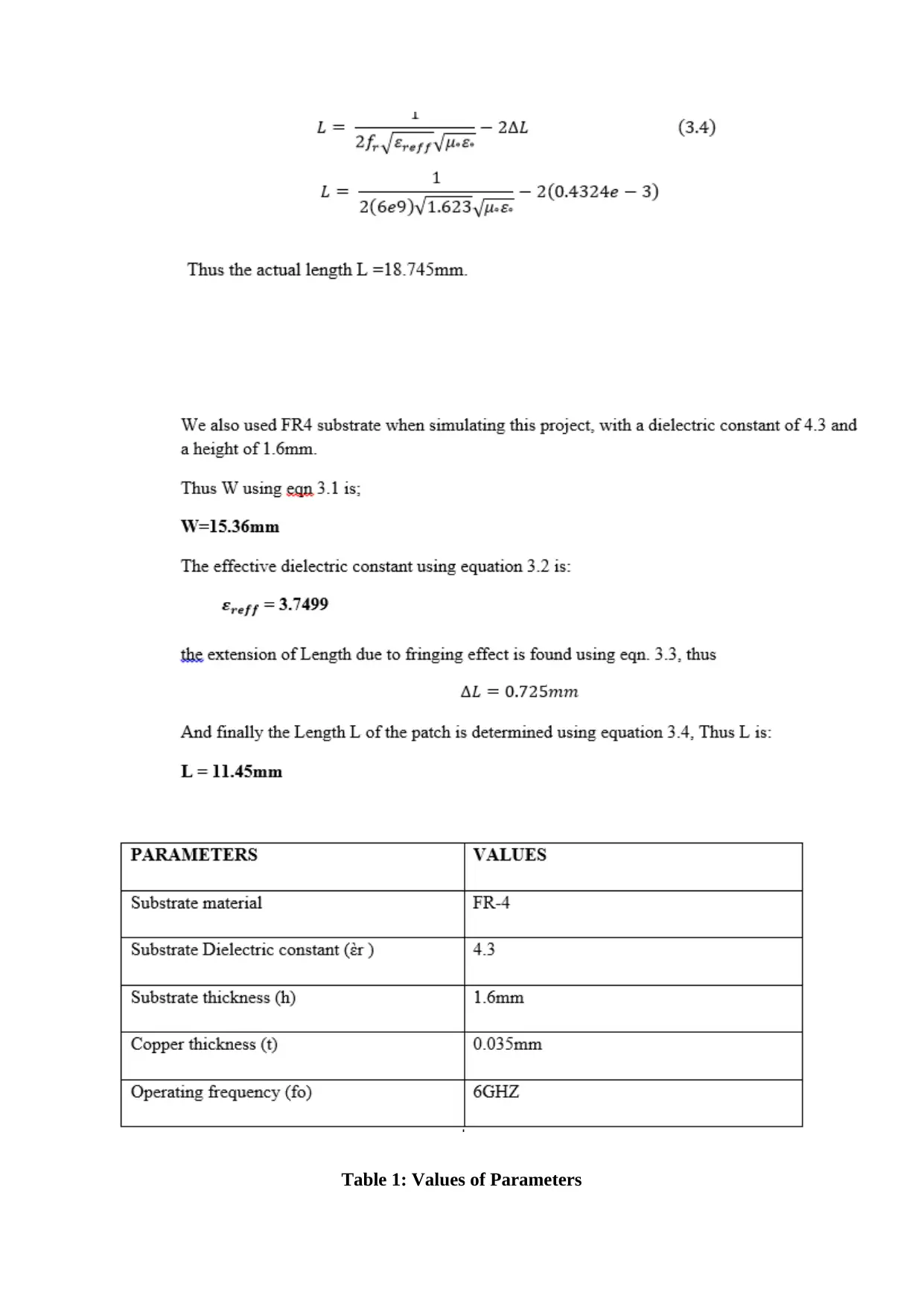
Computing the actual length,
I calculated the extension of the length ΔL due to the fringing effects
Computing the actual length,
Table 1: Values of Parameters
Secure Best Marks with AI Grader
Need help grading? Try our AI Grader for instant feedback on your assignments.
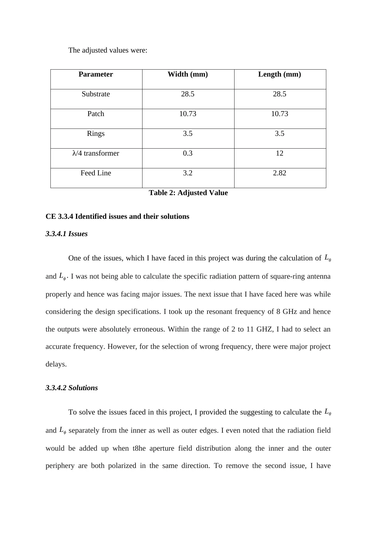
The adjusted values were:
Parameter Width (mm) Length (mm)
Substrate 28.5 28.5
Patch 10.73 10.73
Rings 3.5 3.5
λ/4 transformer 0.3 12
Feed Line 3.2 2.82
Table 2: Adjusted Value
CE 3.3.4 Identified issues and their solutions
3.3.4.1 Issues
One of the issues, which I have faced in this project was during the calculation of Lθ
and Lϕ . I was not being able to calculate the specific radiation pattern of square-ring antenna
properly and hence was facing major issues. The next issue that I have faced here was while
considering the design specifications. I took up the resonant frequency of 8 GHz and hence
the outputs were absolutely erroneous. Within the range of 2 to 11 GHZ, I had to select an
accurate frequency. However, for the selection of wrong frequency, there were major project
delays.
3.3.4.2 Solutions
To solve the issues faced in this project, I provided the suggesting to calculate the Lθ
and Lϕ separately from the inner as well as outer edges. I even noted that the radiation field
would be added up when t8he aperture field distribution along the inner and the outer
periphery are both polarized in the same direction. To remove the second issue, I have
provided the solution of selecting the resonant frequency of 6 GHz and the dielectric constant
of 4.3. Hence our issues were resolved.
CE 3.3.5 Plan to produce creative and innovative work
My main plan was producing an innovative as well as creative effort by effectively
working together as a group. I also sub divided our works properly and ensured that the
individual parts are completed with efficiency.
CE 3.3.6 Collaborative Work
I and my project members completed the work by working collaboratively. We
organized several workshops for identifying our flaws within the project and then executed
the project perfectly. Moreover, I even arranged group meetings for this work.
CE 3.4 Project Review
CE 3.4.1 Project Overview
I have efficiently ordered each and every material needed for the project. I even
documented the results during integrating continuity tests. I have used my knowledge of CST
microwave studio for properly simulating the project and network analyser to test the project
results.
CE 3.4.2 My Contribution to work
I have successfully made this design of micro strip patch antenna in this project, since
I was the senior electronics engineer. Moreover, I even calculated the design parameters like
output voltage, frequency and then completed the simluation with CST Microwave Studio. I
have also used Network Analyser for the testing purpose.
1 out of 9
Related Documents
Your All-in-One AI-Powered Toolkit for Academic Success.
+13062052269
info@desklib.com
Available 24*7 on WhatsApp / Email
Unlock your academic potential
© 2024 | Zucol Services PVT LTD | All rights reserved.