Traffic Light Controller Design: ELEC2141 Assignment Solution

Verified

Added on  2023/04/06

|13
|839
|100
Project
AI Summary
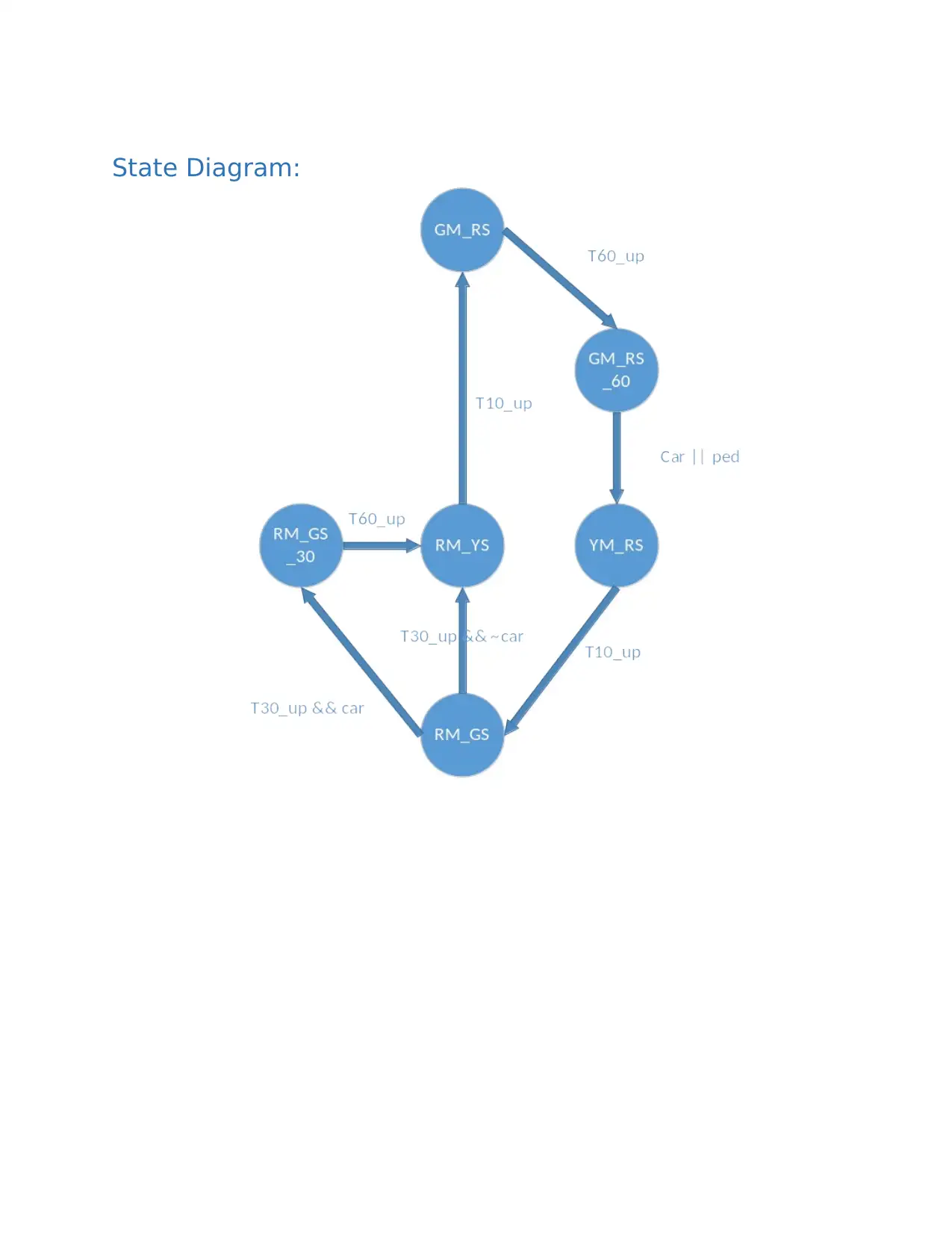
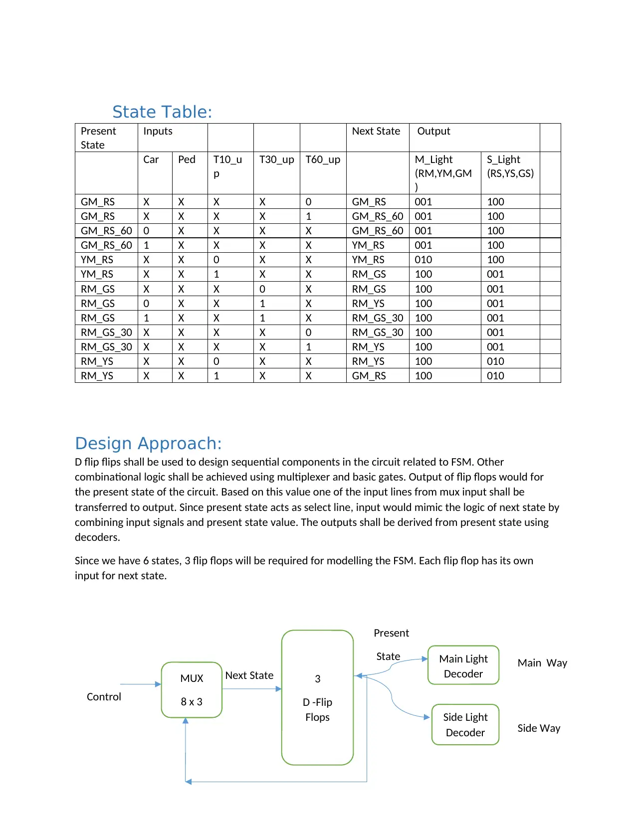
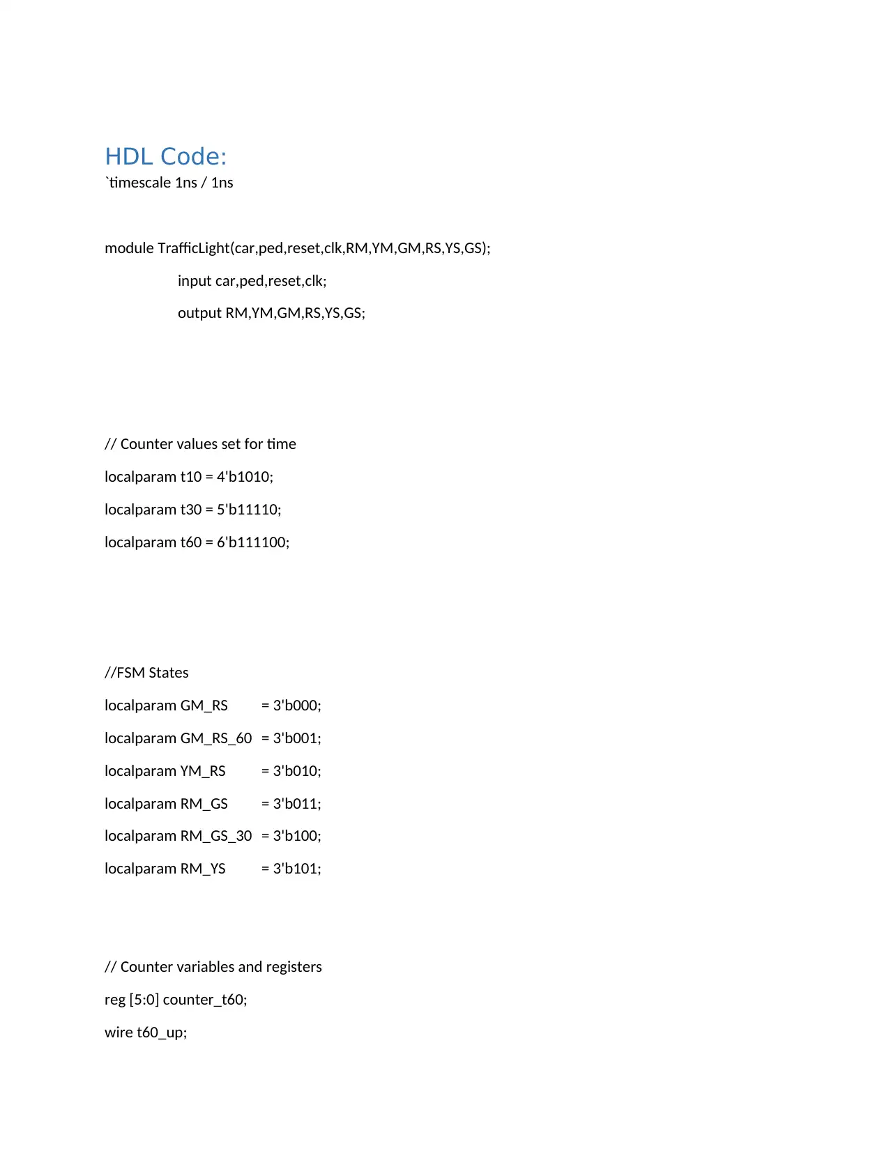
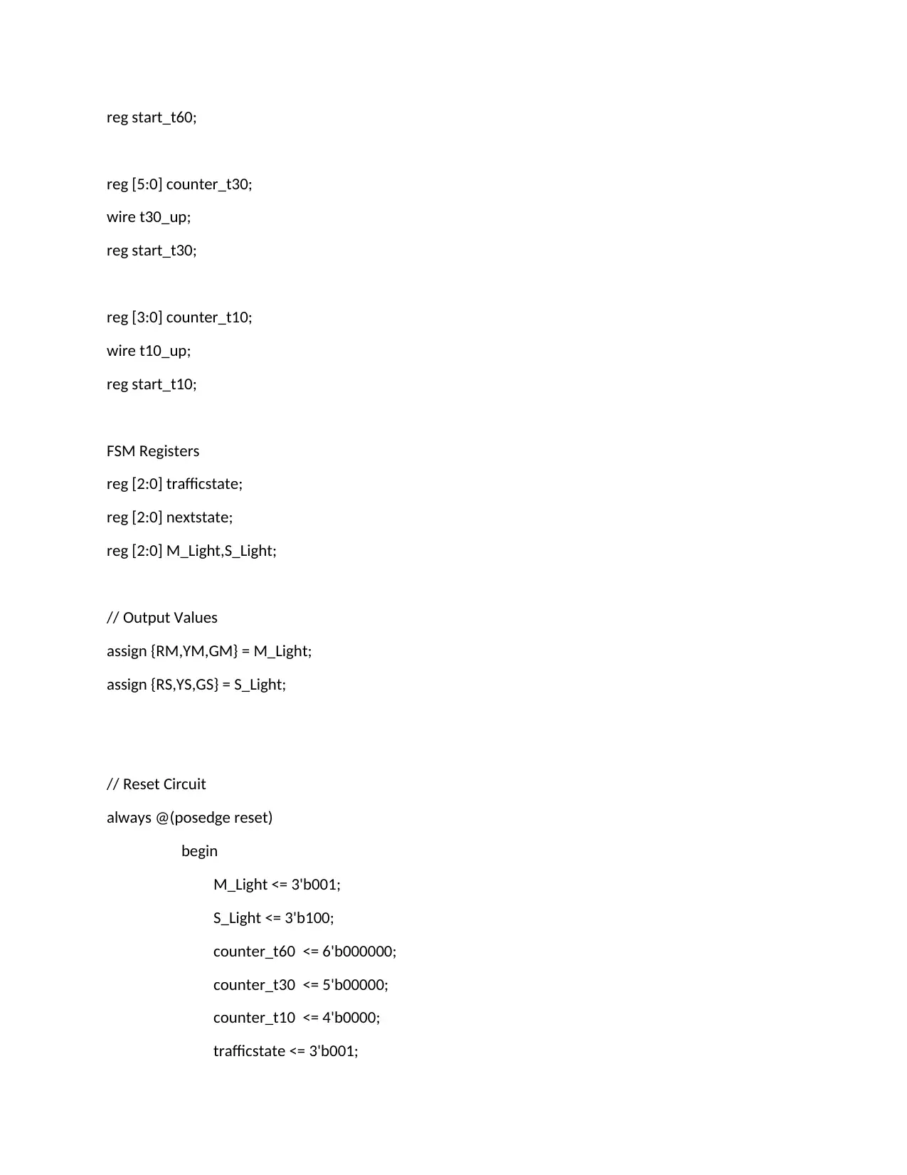
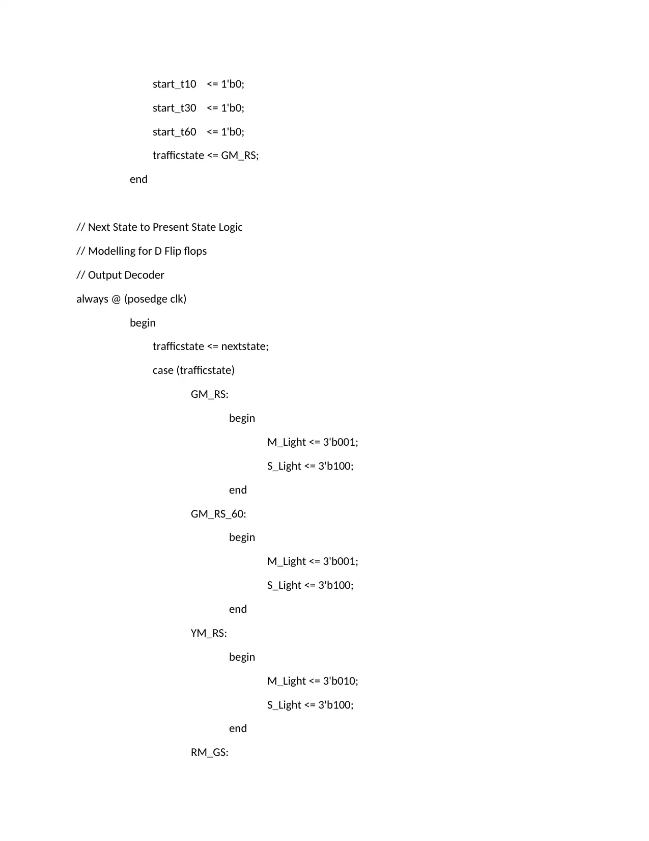
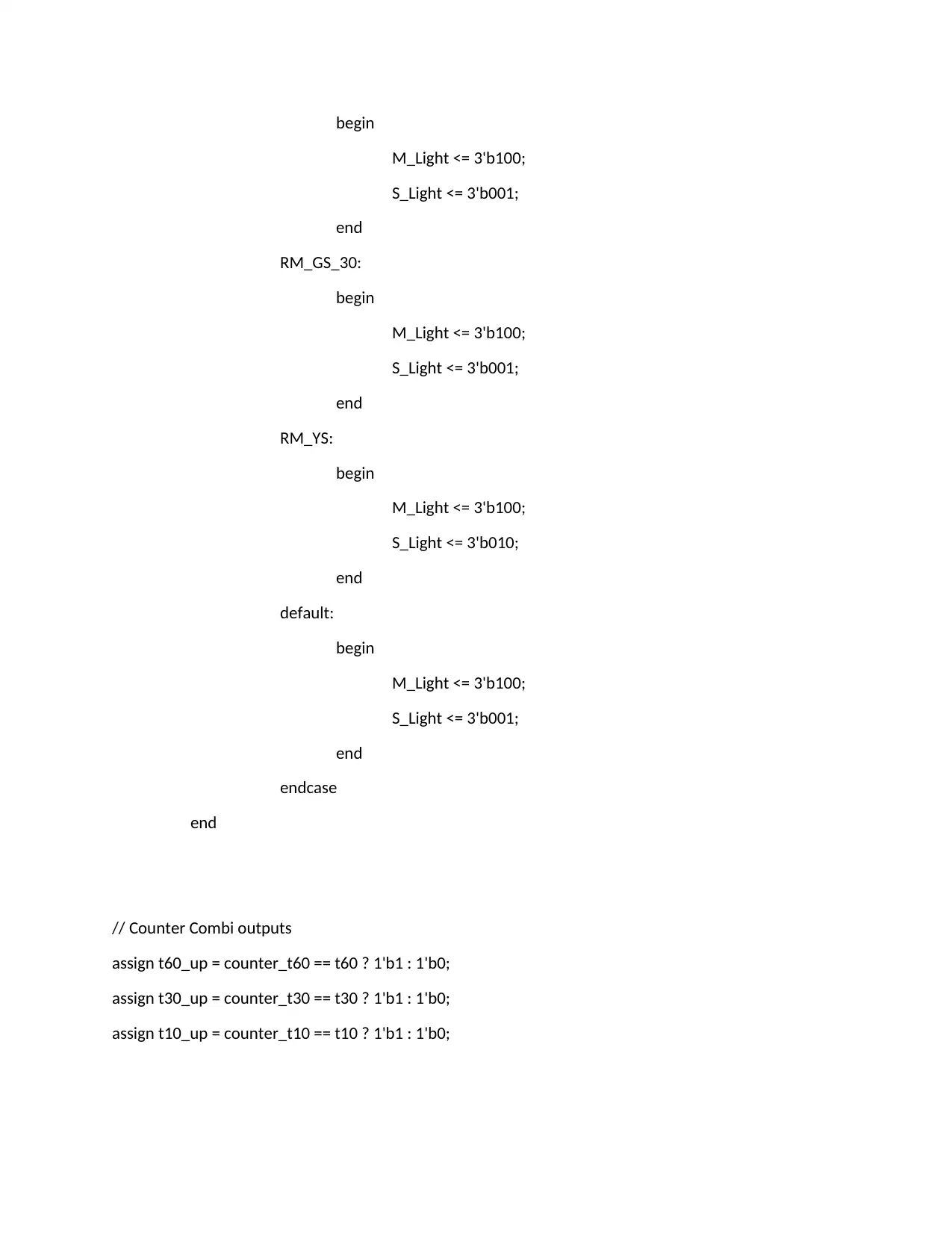
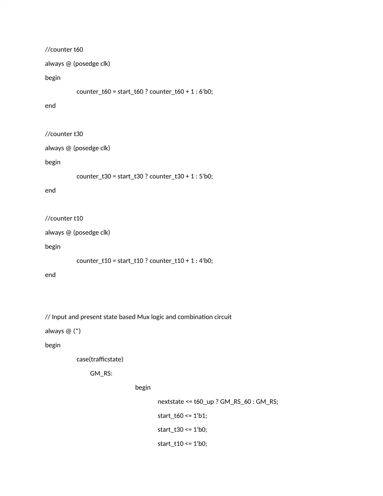
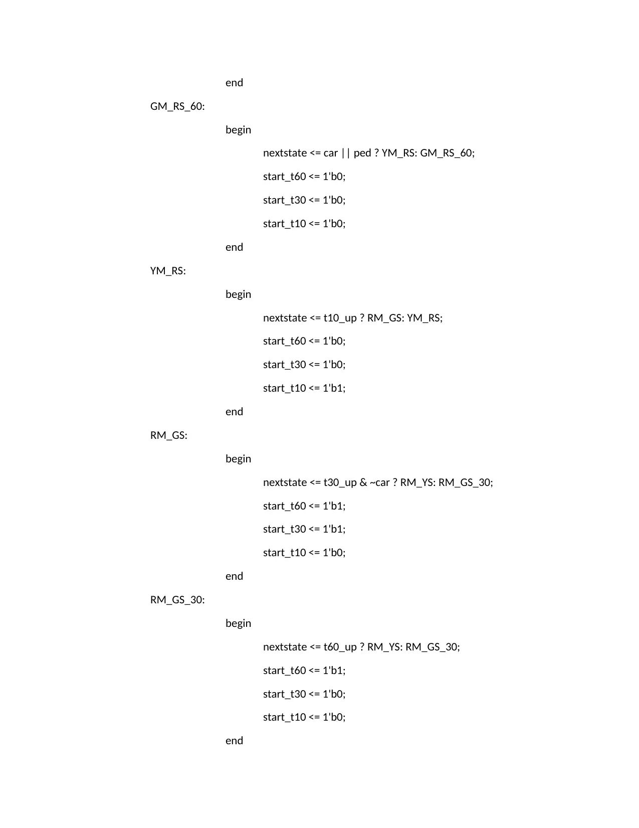
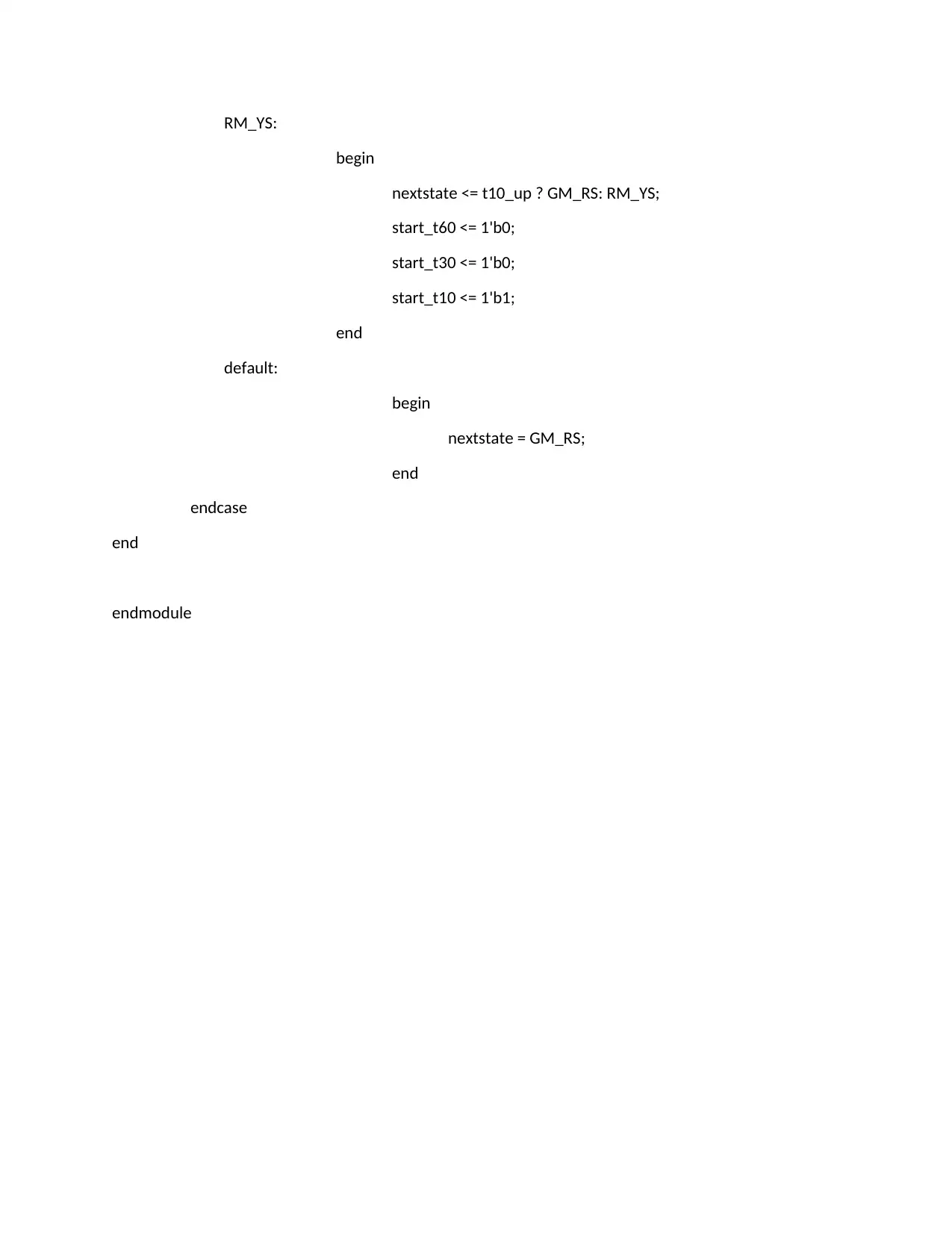
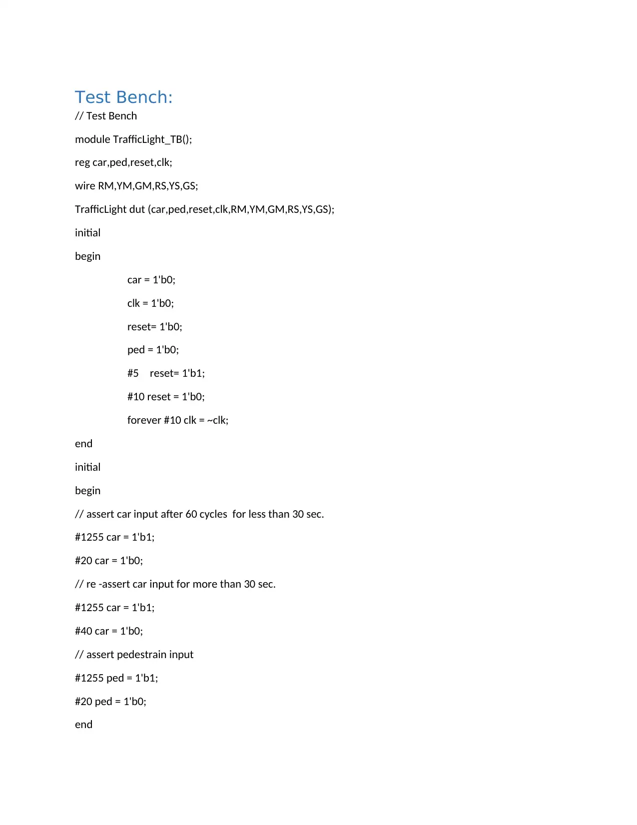
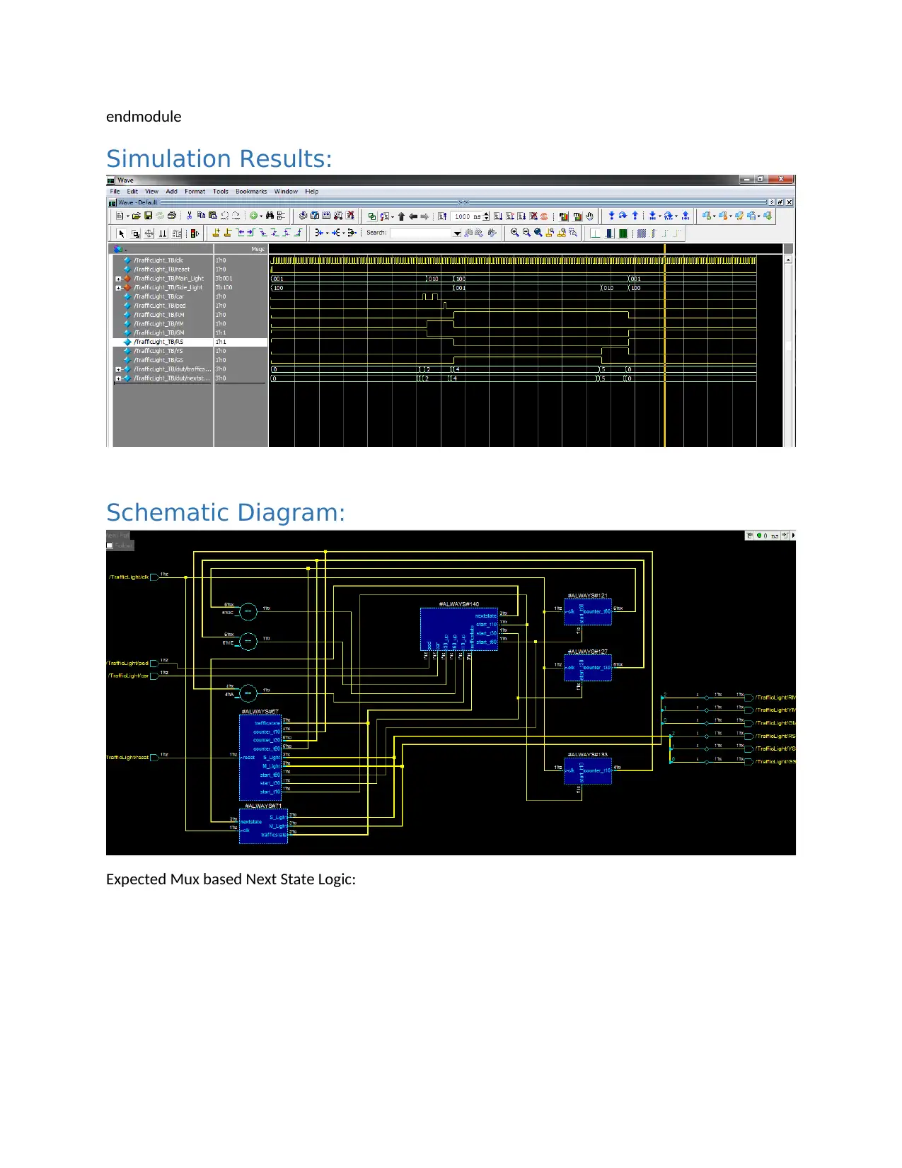
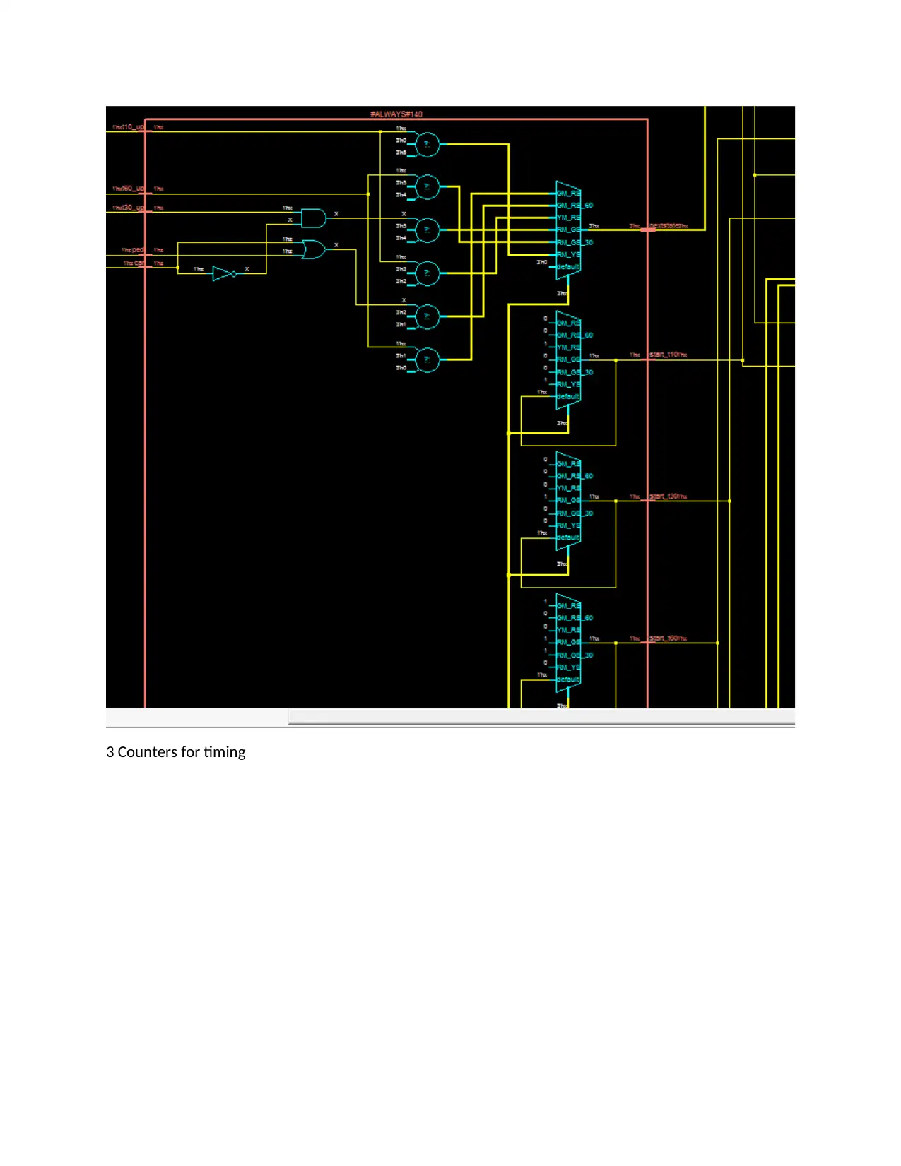
This document presents a detailed solution for a traffic light controller design, addressing the requirements of the ELEC2141 Digital Circuit Design assignment. The solution begins with a state diagram and state table, followed by a design approach utilizing D flip-flops for sequential components and multiplexers with basic gates for combinational logic. The assignment includes the HDL code in Verilog, defining states, counters, and logic for the traffic light's operation, along with a test bench for simulation and verification. The test bench simulates various scenarios, including car and pedestrian inputs. The simulation results, schematic diagram, and expected MUX-based next-state logic are also provided, ensuring a comprehensive understanding of the traffic light controller's functionality. The assignment is a complete project solution, incorporating all necessary components for a thorough design and implementation of the traffic light controller.
Document Page
State Diagram:
tabler-icon-diamond-filled.svg

Secure Best Marks with AI Grader

Need help grading? Try our AI Grader for instant feedback on your assignments.
Document Page
State Table:
Present
State
Inputs Next State Output
Car Ped T10_u
p
T30_up T60_up M_Light
(RM,YM,GM
)
S_Light
(RS,YS,GS)
GM_RS X X X X 0 GM_RS 001 100
GM_RS X X X X 1 GM_RS_60 001 100
GM_RS_60 0 X X X X GM_RS_60 001 100
GM_RS_60 1 X X X X YM_RS 001 100
YM_RS X X 0 X X YM_RS 010 100
YM_RS X X 1 X X RM_GS 100 001
RM_GS X X X 0 X RM_GS 100 001
RM_GS 0 X X 1 X RM_YS 100 001
RM_GS 1 X X 1 X RM_GS_30 100 001
RM_GS_30 X X X X 0 RM_GS_30 100 001
RM_GS_30 X X X X 1 RM_YS 100 001
RM_YS X X 0 X X RM_YS 100 010
RM_YS X X 1 X X GM_RS 100 010
Design Approach:
D flip flips shall be used to design sequential components in the circuit related to FSM. Other
combinational logic shall be achieved using multiplexer and basic gates. Output of flip flops would for
the present state of the circuit. Based on this value one of the input lines from mux input shall be
transferred to output. Since present state acts as select line, input would mimic the logic of next state by
combining input signals and present state value. The outputs shall be derived from present state using
decoders.
Since we have 6 states, 3 flip flops will be required for modelling the FSM. Each flip flop has its own
input for next state.
3
D -Flip
Flops
Main Light
Decoder
Side Light
Decoder
MUX
8 x 3
Next State
Control
Present
State Main Way
Side Way
Document Page
HDL Code:
`timescale 1ns / 1ns
module TrafficLight(car,ped,reset,clk,RM,YM,GM,RS,YS,GS);
input car,ped,reset,clk;
output RM,YM,GM,RS,YS,GS;
// Counter values set for time
localparam t10 = 4'b1010;
localparam t30 = 5'b11110;
localparam t60 = 6'b111100;
//FSM States
localparam GM_RS = 3'b000;
localparam GM_RS_60 = 3'b001;
localparam YM_RS = 3'b010;
localparam RM_GS = 3'b011;
localparam RM_GS_30 = 3'b100;
localparam RM_YS = 3'b101;
// Counter variables and registers
reg [5:0] counter_t60;
wire t60_up;
Document Page
reg start_t60;
reg [5:0] counter_t30;
wire t30_up;
reg start_t30;
reg [3:0] counter_t10;
wire t10_up;
reg start_t10;
FSM Registers
reg [2:0] trafficstate;
reg [2:0] nextstate;
reg [2:0] M_Light,S_Light;
// Output Values
assign {RM,YM,GM} = M_Light;
assign {RS,YS,GS} = S_Light;
// Reset Circuit
always @(posedge reset)
begin
M_Light <= 3'b001;
S_Light <= 3'b100;
counter_t60 <= 6'b000000;
counter_t30 <= 5'b00000;
counter_t10 <= 4'b0000;
trafficstate <= 3'b001;
tabler-icon-diamond-filled.svg

Secure Best Marks with AI Grader

Need help grading? Try our AI Grader for instant feedback on your assignments.
Document Page
start_t10 <= 1'b0;
start_t30 <= 1'b0;
start_t60 <= 1'b0;
trafficstate <= GM_RS;
end
// Next State to Present State Logic
// Modelling for D Flip flops
// Output Decoder
always @ (posedge clk)
begin
trafficstate <= nextstate;
case (trafficstate)
GM_RS:
begin
M_Light <= 3'b001;
S_Light <= 3'b100;
end
GM_RS_60:
begin
M_Light <= 3'b001;
S_Light <= 3'b100;
end
YM_RS:
begin
M_Light <= 3'b010;
S_Light <= 3'b100;
end
RM_GS:
Document Page
begin
M_Light <= 3'b100;
S_Light <= 3'b001;
end
RM_GS_30:
begin
M_Light <= 3'b100;
S_Light <= 3'b001;
end
RM_YS:
begin
M_Light <= 3'b100;
S_Light <= 3'b010;
end
default:
begin
M_Light <= 3'b100;
S_Light <= 3'b001;
end
endcase
end
// Counter Combi outputs
assign t60_up = counter_t60 == t60 ? 1'b1 : 1'b0;
assign t30_up = counter_t30 == t30 ? 1'b1 : 1'b0;
assign t10_up = counter_t10 == t10 ? 1'b1 : 1'b0;
Document Page
//counter t60
always @ (posedge clk)
begin
counter_t60 = start_t60 ? counter_t60 + 1 : 6'b0;
end
//counter t30
always @ (posedge clk)
begin
counter_t30 = start_t30 ? counter_t30 + 1 : 5'b0;
end
//counter t10
always @ (posedge clk)
begin
counter_t10 = start_t10 ? counter_t10 + 1 : 4'b0;
end
// Input and present state based Mux logic and combination circuit
always @ (*)
begin
case(trafficstate)
GM_RS:
begin
nextstate <= t60_up ? GM_RS_60 : GM_RS;
start_t60 <= 1'b1;
start_t30 <= 1'b0;
start_t10 <= 1'b0;
tabler-icon-diamond-filled.svg

Paraphrase This Document

Need a fresh take? Get an instant paraphrase of this document with our AI Paraphraser
Document Page
end
GM_RS_60:
begin
nextstate <= car || ped ? YM_RS: GM_RS_60;
start_t60 <= 1'b0;
start_t30 <= 1'b0;
start_t10 <= 1'b0;
end
YM_RS:
begin
nextstate <= t10_up ? RM_GS: YM_RS;
start_t60 <= 1'b0;
start_t30 <= 1'b0;
start_t10 <= 1'b1;
end
RM_GS:
begin
nextstate <= t30_up & ~car ? RM_YS: RM_GS_30;
start_t60 <= 1'b1;
start_t30 <= 1'b1;
start_t10 <= 1'b0;
end
RM_GS_30:
begin
nextstate <= t60_up ? RM_YS: RM_GS_30;
start_t60 <= 1'b1;
start_t30 <= 1'b0;
start_t10 <= 1'b0;
end
Document Page
RM_YS:
begin
nextstate <= t10_up ? GM_RS: RM_YS;
start_t60 <= 1'b0;
start_t30 <= 1'b0;
start_t10 <= 1'b1;
end
default:
begin
nextstate = GM_RS;
end
endcase
end
endmodule
Document Page
Test Bench:
// Test Bench
module TrafficLight_TB();
reg car,ped,reset,clk;
wire RM,YM,GM,RS,YS,GS;
TrafficLight dut (car,ped,reset,clk,RM,YM,GM,RS,YS,GS);
initial
begin
car = 1'b0;
clk = 1'b0;
reset= 1'b0;
ped = 1'b0;
#5 reset= 1'b1;
#10 reset = 1'b0;
forever #10 clk = ~clk;
end
initial
begin
// assert car input after 60 cycles for less than 30 sec.
#1255 car = 1'b1;
#20 car = 1'b0;
// re -assert car input for more than 30 sec.
#1255 car = 1'b1;
#40 car = 1'b0;
// assert pedestrain input
#1255 ped = 1'b1;
#20 ped = 1'b0;
end
tabler-icon-diamond-filled.svg

Secure Best Marks with AI Grader

Need help grading? Try our AI Grader for instant feedback on your assignments.
Document Page
endmodule
Simulation Results:
Schematic Diagram:
Expected Mux based Next State Logic:
Document Page
3 Counters for timing
Document Page
chevron_up_icon
1 out of 13
circle_padding
hide_on_mobile
zoom_out_icon
[object Object]