Software Engineering: State Transition Diagram for Oral B Braun 5000
VerifiedAdded on 2022/09/07
|12
|1395
|19
Project
AI Summary
This report details the development of a state transition diagram for the Oral B Braun 5000 electric toothbrush. The analysis begins with an examination of the toothbrush's functionality, including its interaction with the SmartGuide, charging procedures, and various operational modes such as daily clean, whitening, and massage modes. Simulink is employed as a simulation environment in MATLAB to create and test the state transition diagram, ensuring the proper operation of the electric brush. The report includes a state transition table and diagram, illustrating the different states and transitions of the toothbrush. Testing involves creating signal blocks in Simulink to simulate user inputs and pressure, validating the transitions. The conclusion confirms that the specified functionality of the brush has been successfully tested, with the state transitions accurately implemented using Simulink. The SmartGuide plays a crucial role in facilitating these state transitions.
Running head: STATE TRANSITION DIAGRAM
Assignment 1: State Transition Diagram
Name of the Student
Name of the Instructor
Date
Assignment 1: State Transition Diagram
Name of the Student
Name of the Instructor
Date
Paraphrase This Document
Need a fresh take? Get an instant paraphrase of this document with our AI Paraphraser
1
STATE TRANSITION DIAGRAM
Table of Contents
Introduction......................................................................................................................................2
Oral B Braun 5000 functionality and smart guide...........................................................................2
Description of state transition diagram............................................................................................3
State model......................................................................................................................................4
State transition diagram...................................................................................................................4
State transition table........................................................................................................................6
Testing.............................................................................................................................................8
Conclusion.....................................................................................................................................10
Bibliography..................................................................................................................................11
2
STATE TRANSITION DIAGRAM
Introduction
The report is prepared for the development of a state transition diagram after analyzing
the functionality of Oral B toothbrush and verification of the inputs. There are different types of
operational modes of the tooth brush for example mechanism of live feedback integrated with the
IC of the toothbrush used for improvement of brushing experience with the use of smart guide
application. With the smart guide application the toothbrush can be controlled and set to use as
different modes and improve the assistance for the user. Simulink is used as a simulation
environment in MATLAB for the development of the state transition diagram and test it for
analyzing proper working of the electric brush. The graphs generated with the application of
Simulink is used for interpretation because they are simple and have thorough visualization of
the curve. The different states of the toothbrush is considered and some of the steps that are
mandatory is selected for the analysis of the transition. The operation of the provided oral B
5000 toothbrush is quite similar with most of the model. The toothbrush is considered as one of
the best electric brush of its class and it is also recommended by multiple dentist since it has the
ability to eliminate most of the dental problems after using it continuously for a week.
Oral B Braun 5000 functionality and smart guide
The oral b 5000 have the following functionality such as:
Simplified charging procedure of the electric toothbrush since the plug of the toothbrush
is needed to be plugged in to an electric socket and an indicator light shows the status of
charging. When the brush gets fully charged the green light glows and it can work for 2
days for a default brushing of 2 times a day.
⊘ This is a preview!⊘
Do you want full access?
Subscribe today to unlock all pages.

Trusted by 1+ million students worldwide
3
STATE TRANSITION DIAGRAM
Two modes are present in the brush i.e. two minute and professional mode. The
professional mode is used for changing the interval of time for brushing and can be used
with the other modes and operated for a period of 30 seconds. The daily cleaning mode
on the brush can be used for 45 sec and the green indicator in the brush starts flashing
after the expiry of the time and a shutter sound is played. For the two minute timer mode
the operation is similar but in this mode the time for brushing cannot be modified.
The experience of brushing can be fetched using a computer system at a real time by
connecting the Bluetooth sensor installed in the brush that sends continuous data. The
smart screen can also provide suggestion about brushing.
The most beneficial functionality is the additional pressure feature which is used for
detecting excess pressure applied by the user during brushing and lights the red light and
generates a warning message on the smart screen. The feature can improve the safety and
if the toothbrush operates in daily clean or deep clean mode it is switched to sensitive
mode.
Description of state transition diagram
State Input of signal for state
transition
State
OFF State n=0 or u<0 y= -1
Tongue Clean mode n=6 y=7
Daily clean mode n=1 y=2
ON state n>0 y= 1
Paraphrase This Document
Need a fresh take? Get an instant paraphrase of this document with our AI Paraphraser
4
STATE TRANSITION DIAGRAM
Whitening mode n=4 y=5
Waiting n>0 (2 sec duration) y= 0
Deep clean mode n=5 y=6
Massage mode n=3 y=4
Sensitive mode n=2, x=1 y=3
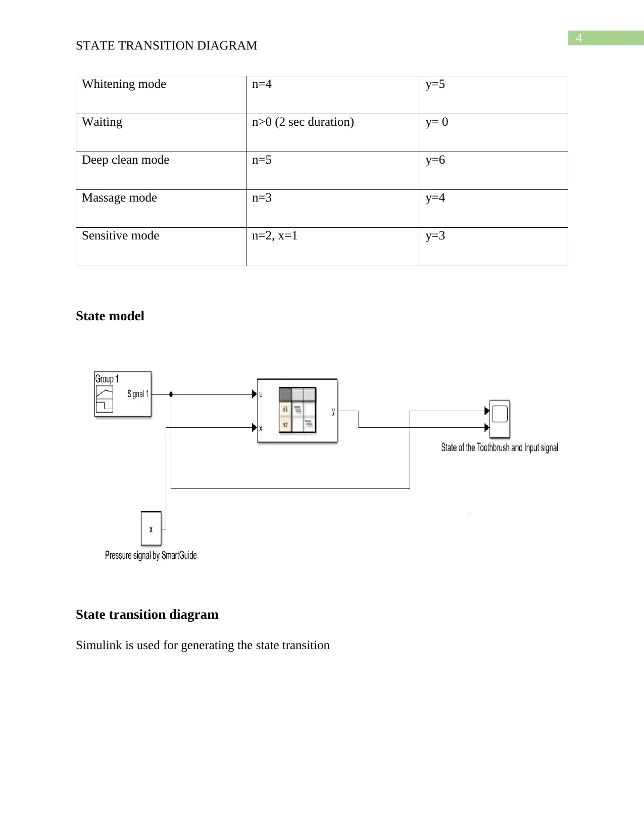
State model
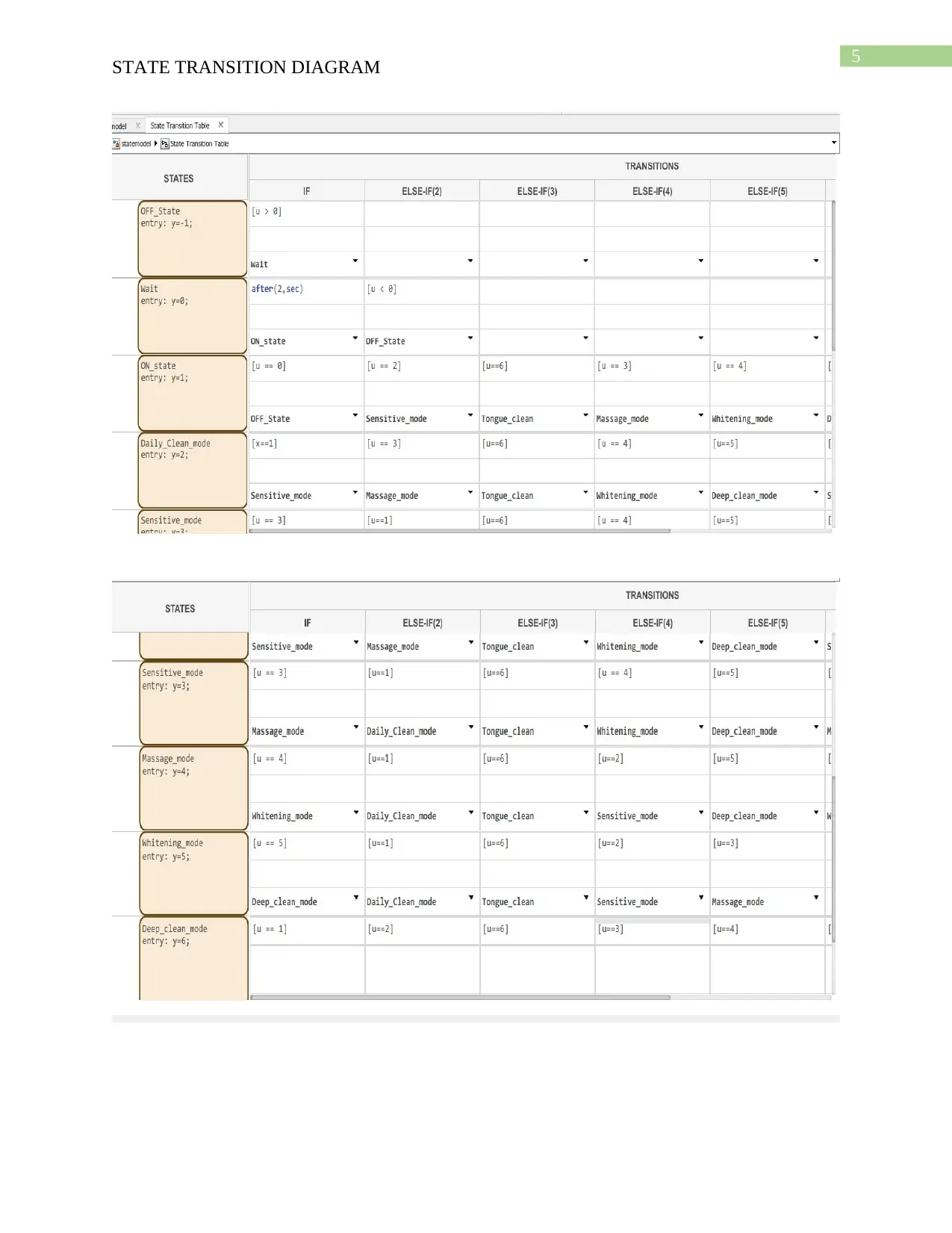
State transition diagram
Simulink is used for generating the state transition
STATE TRANSITION DIAGRAM
Whitening mode n=4 y=5
Waiting n>0 (2 sec duration) y= 0
Deep clean mode n=5 y=6
Massage mode n=3 y=4
Sensitive mode n=2, x=1 y=3
State model
State transition diagram
Simulink is used for generating the state transition
5
STATE TRANSITION DIAGRAM
STATE TRANSITION DIAGRAM
⊘ This is a preview!⊘
Do you want full access?
Subscribe today to unlock all pages.

Trusted by 1+ million students worldwide
6
STATE TRANSITION DIAGRAM
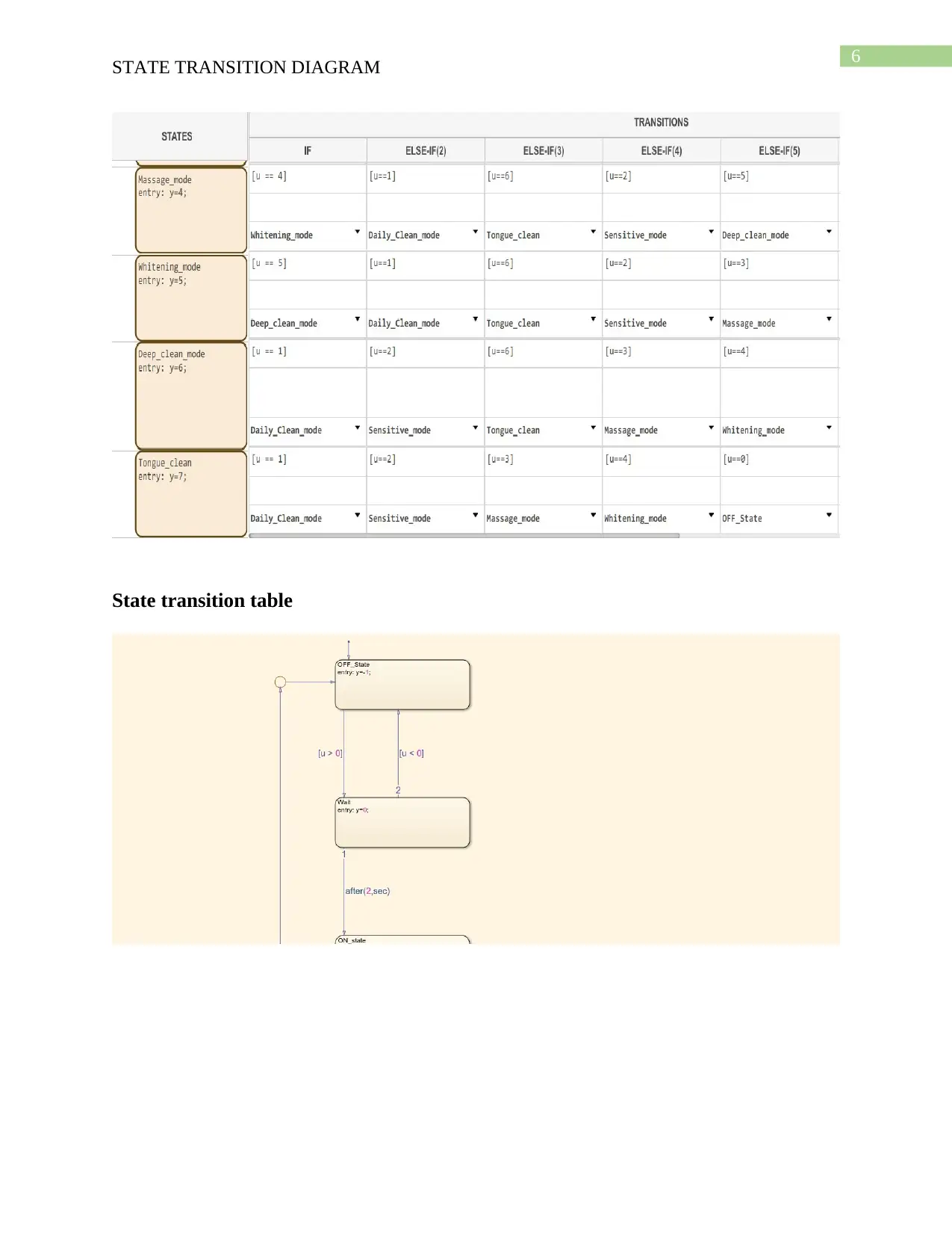
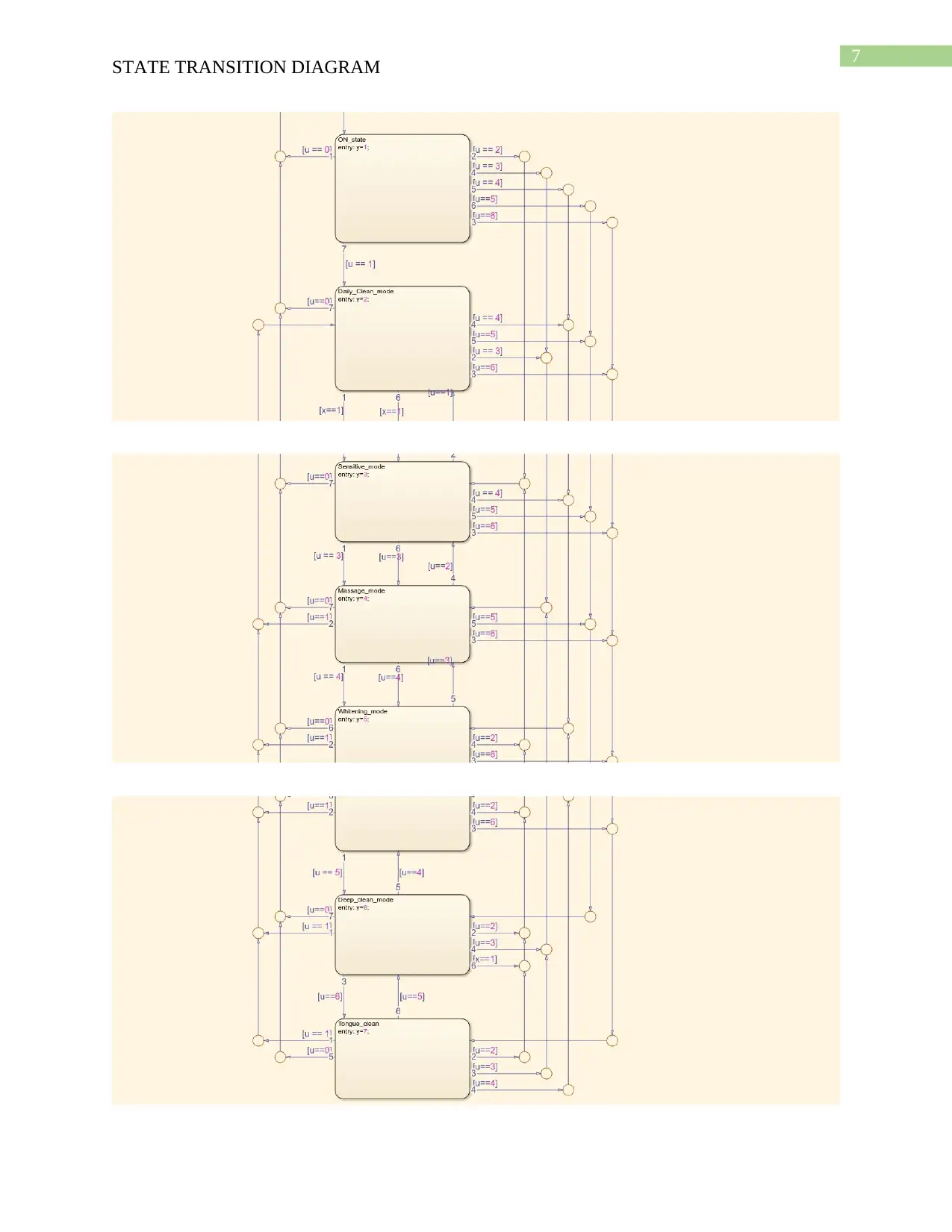
State transition table
STATE TRANSITION DIAGRAM
State transition table
Paraphrase This Document
Need a fresh take? Get an instant paraphrase of this document with our AI Paraphraser
7
STATE TRANSITION DIAGRAM
STATE TRANSITION DIAGRAM
8
STATE TRANSITION DIAGRAM
Testing
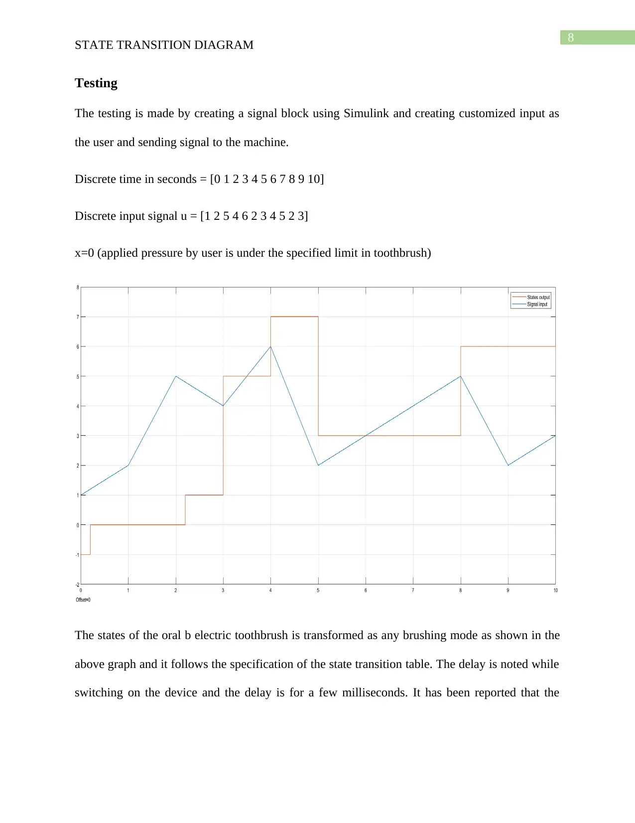
The testing is made by creating a signal block using Simulink and creating customized input as
the user and sending signal to the machine.
Discrete time in seconds = [0 1 2 3 4 5 6 7 8 9 10]
Discrete input signal u = [1 2 5 4 6 2 3 4 5 2 3]
x=0 (applied pressure by user is under the specified limit in toothbrush)
The states of the oral b electric toothbrush is transformed as any brushing mode as shown in the
above graph and it follows the specification of the state transition table. The delay is noted while
switching on the device and the delay is for a few milliseconds. It has been reported that the
⊘ This is a preview!⊘
Do you want full access?
Subscribe today to unlock all pages.

Trusted by 1+ million students worldwide
9
STATE TRANSITION DIAGRAM
delay is uniform and found to be minimum. The electric brush operates using the massage mode
that can be depicted as y=4 when the input is n=3.
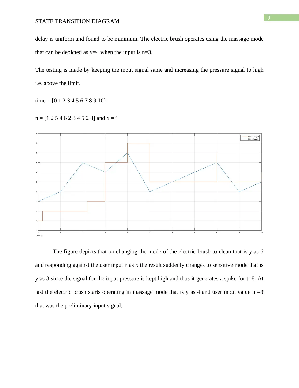
The testing is made by keeping the input signal same and increasing the pressure signal to high
i.e. above the limit.
time = [0 1 2 3 4 5 6 7 8 9 10]
n = [1 2 5 4 6 2 3 4 5 2 3] and x = 1
The figure depicts that on changing the mode of the electric brush to clean that is y as 6
and responding against the user input n as 5 the result suddenly changes to sensitive mode that is
y as 3 since the signal for the input pressure is kept high and thus it generates a spike for t=8. At
last the electric brush starts operating in massage mode that is y as 4 and user input value n =3
that was the preliminary input signal.
Paraphrase This Document
Need a fresh take? Get an instant paraphrase of this document with our AI Paraphraser
10
STATE TRANSITION DIAGRAM
Conclusion
The report on the oral B Braun 5000 electric tooth brush model concludes that all the
functionality specified for the brush has been tested and works fine. Multiple brushing modes are
identified and is considered as important stage. The state transition are tested using by creating
the model in Simulink and testing it with different inputs as a user. Pressure is applied arbitrarily
as an input in the Simulink model and the plot graphs are obtained that shows the transitions
following different rules that are specified in the state transition table. Thus it can be said that the
state transition has been successfully implemented using Simulink. The signal of pressure and
also the input from the user point of view are taken as random for testing the electric tooth brush
operation and brushing behavior. The external signal can be converted into values with the help
of the smart guide that acts as the main cause for state transition.
11
STATE TRANSITION DIAGRAM
Bibliography
[1]A. Gruca, A. Brachman, S. Kozielski and T. Czachórski, Man-machine interactions 4. .
[2]Y. Odeh, D. Tbaishat, S. Sharma, F. Aburub, A. Tbakhi and M. Odeh, 2018, November.
Using Business Process Models to Inform Deriving State Transition Diagrams: Applied to BMT
Lab in a Cancer Organization. In 2018 1st International Conference on Cancer Care Informatics
(CCI) (pp. 180-187). IEEE.
[3]E.V. Sunitha and P. Samuel, 2019. Automatic code generation from UML state chart
diagrams. IEEE Access, 7, pp.8591-8608.
[4]D. Kerr, 2016. Visualizing changes in strategy use across attempts via state diagrams: a case
study. International Journal of Computer Games Technology, 2016, p.4.
[5]D. Bergman, A.A. Cire, W.J. van Hoeve and J.N. Hooker, 2016. Discrete optimization with
decision diagrams. INFORMS Journal on Computing, 28(1), pp.47-66.
[6] J. Hooker, 2018. What Decision Diagrams Can Do for You.
[7] D. Bergman, A.A. Cire, W.J. Van Hoeve and J. Hooker, 2016. Decision diagrams for
optimization (Vol. 1). New York, NY: Springer International Publishing.
[8] C. Franco, and J. Pablo, 2017. Graph drawing strategies for large UML State Machine
diagrams (Master's thesis).
⊘ This is a preview!⊘
Do you want full access?
Subscribe today to unlock all pages.

Trusted by 1+ million students worldwide
1 out of 12
Related Documents
Your All-in-One AI-Powered Toolkit for Academic Success.
+13062052269
info@desklib.com
Available 24*7 on WhatsApp / Email
![[object Object]](/_next/static/media/star-bottom.7253800d.svg)
Unlock your academic potential
Copyright © 2020–2026 A2Z Services. All Rights Reserved. Developed and managed by ZUCOL.


