Engineering Science TMA: Analysis of Beams, Columns in Static Systems
VerifiedAdded on 2023/04/22
|13
|1584
|317
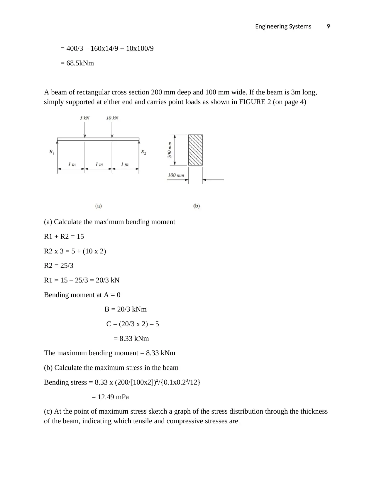
Homework Assignment
AI Summary
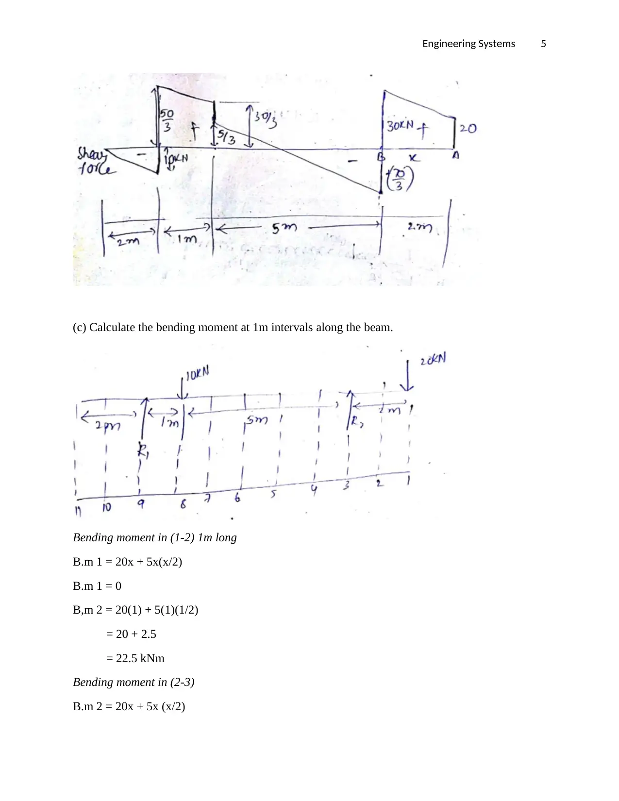
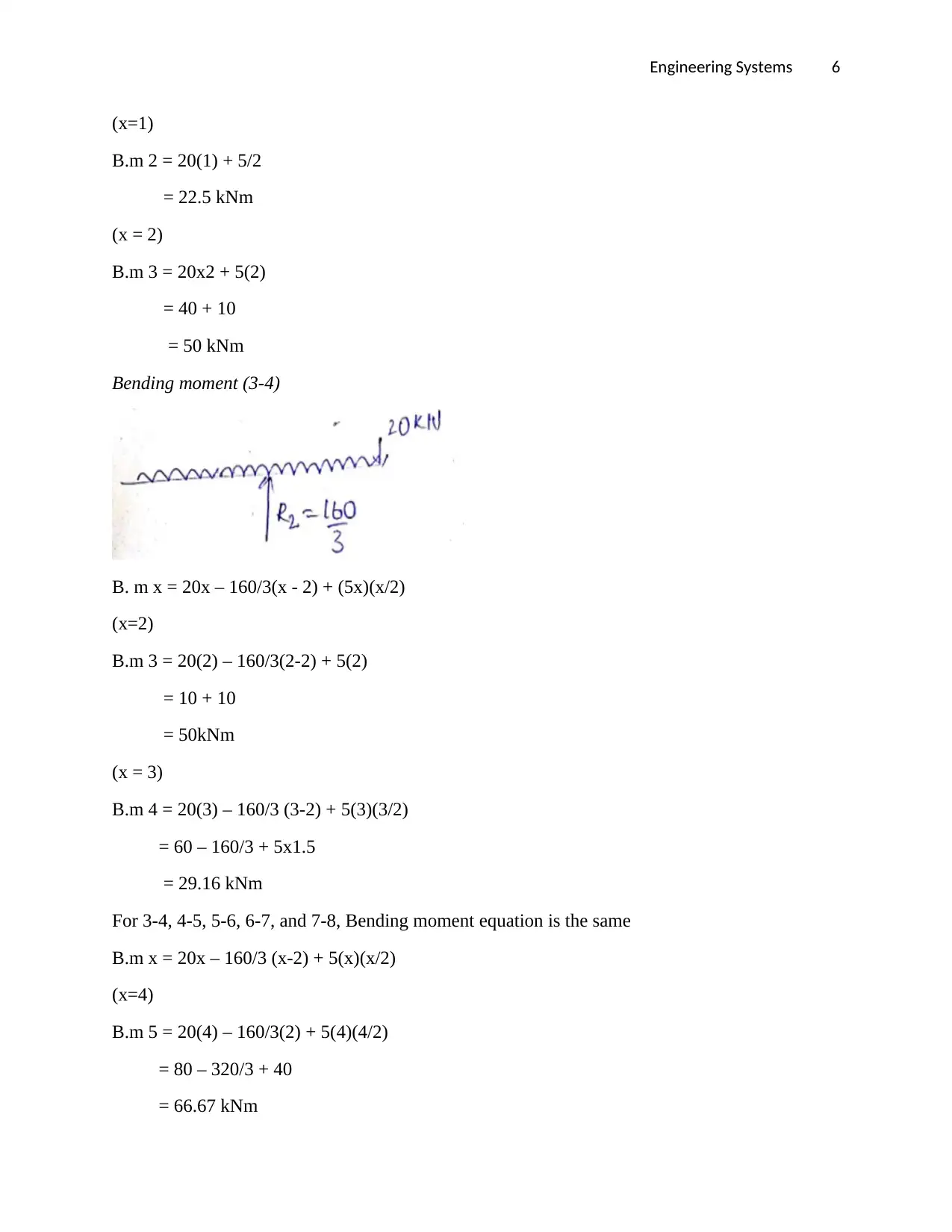
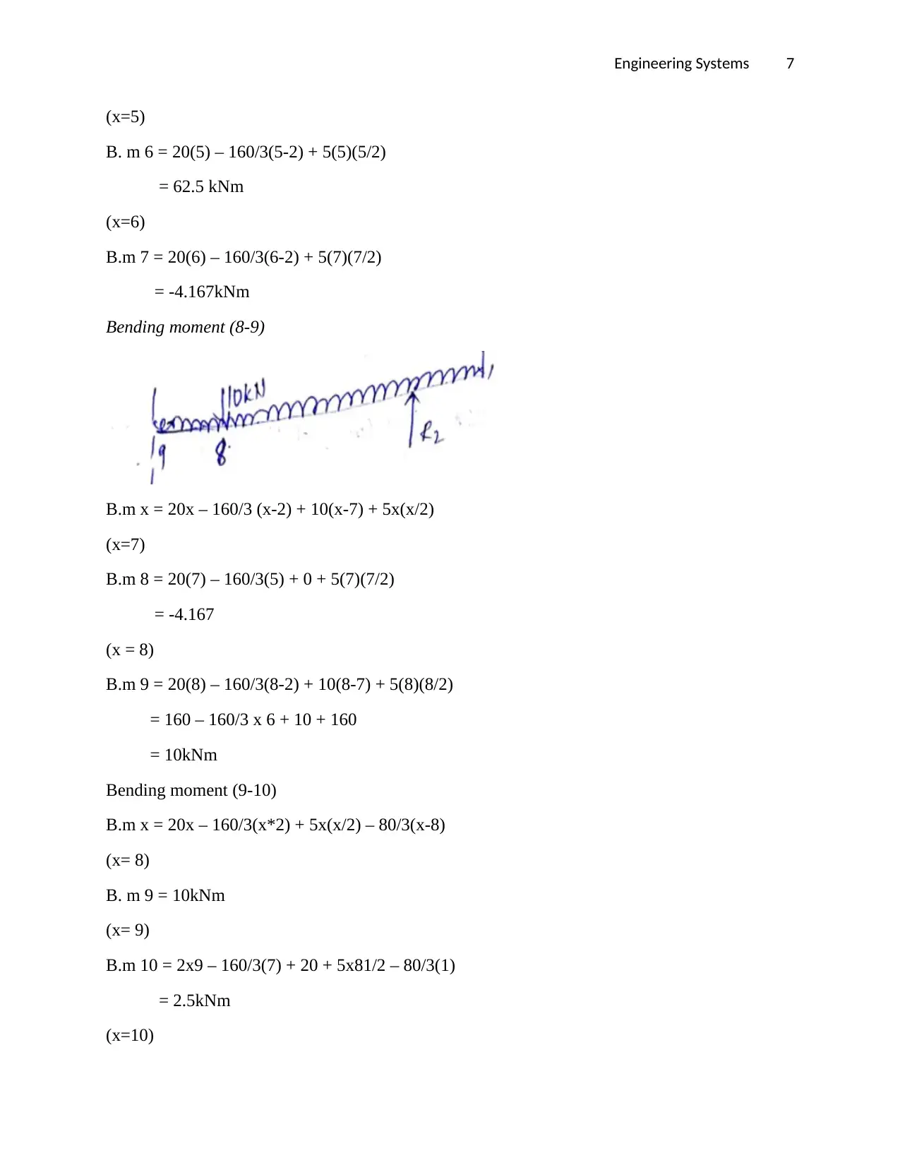
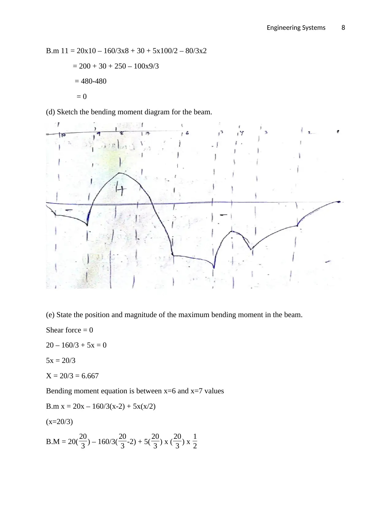
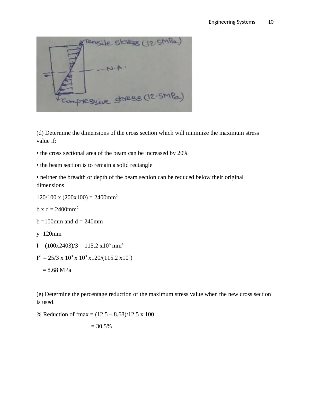
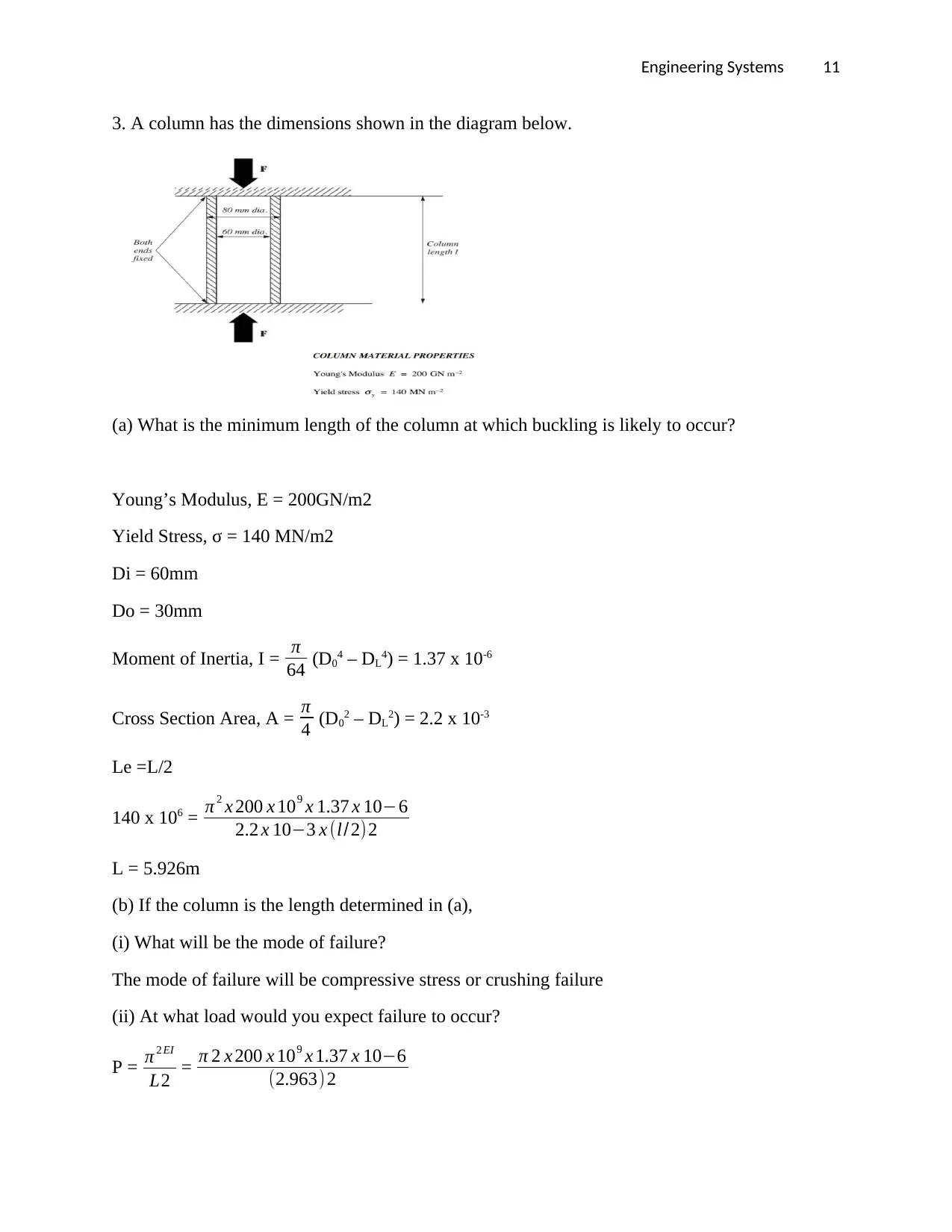
This document presents a detailed solution to an engineering assignment focused on static engineering systems. It includes calculations for vertical reactions at supports, shear force diagrams, bending moment calculations at 1m intervals, and bending moment diagrams for a loaded beam. The solution also covers the determination of maximum bending moment, maximum stress in a beam, and stress distribution through the beam's thickness. Furthermore, it addresses column buckling, including determining the minimum column length for buckling to occur, identifying the mode of failure, and calculating the expected failure load under different conditions. The document concludes with a bibliography, citing relevant resources on dynamics and control in mechanical engineering systems.
1 out of 13
Related Documents


Your All-in-One AI-Powered Toolkit for Academic Success.
+13062052269
info@desklib.com
Available 24*7 on WhatsApp / Email
![[object Object]](/_next/static/media/star-bottom.7253800d.svg)
Copyright © 2020–2026 A2Z Services. All Rights Reserved. Developed and managed by ZUCOL.