Homework Assignment: Shear and Moment Diagrams in Engineering Statics
VerifiedAdded on 2023/05/31
|10
|1235
|367
Homework Assignment
AI Summary
This document presents a complete solution to a statics homework assignment focusing on the construction of shear and moment diagrams for two different beam configurations. The solution includes free body diagrams, step-by-step calculations for shear forces and bending moments, and the resulting shear force and bending moment diagrams. The analysis covers distributed loads and point loads, detailing the determination of reaction forces, shear force values at various points along the beam, and the calculation of bending moments. The document offers a comprehensive guide to understanding and solving shear and moment diagram problems, crucial concepts in engineering mechanics.

University
Statics
By
Your Name
Date
Page 1 of 10
© <Your Name> 2018
Statics
By
Your Name
Date
Page 1 of 10
© <Your Name> 2018
Paraphrase This Document
Need a fresh take? Get an instant paraphrase of this document with our AI Paraphraser
Question 1
Answers
Free Body Diagram
The sum of clockwise moments is equal to the sum of anti-clockwise moments (Ramamurti,
2011). Thus the sum of the individual clockwise moments and the individual anticlockwise
moments adds up to zero.
∑ M A =0
30 Rr = [ 5 ft ( 10 ftx 2 kips ) +25 ft (10 ftx 2kips) ]
Rr = 600
30 =20 kips
Therefore, the reaction force on the right hand side is equal to 20kips.
∑ MD =0
30 Rl= [ 25 ft ( 2 kipsx 10 ft ) +5 ft (10 ft x 2 kips) ]
Rl= 600
30 =20 kips
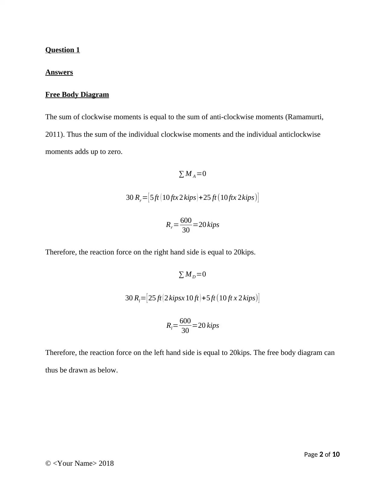
Therefore, the reaction force on the left hand side is equal to 20kips. The free body diagram can
thus be drawn as below.
Page 2 of 10
© <Your Name> 2018
Shear Force Diagram
Considering the first part of the beam AB. The shear force can be calculated as:
V ( X1 ) =+ RA −F1 ( X 1−0)
Where F1 is the distributed load. Therefore,
V ( 0 )=+ 20−2 ( 0−0 )=20 kips
V ( 10 )=+20−2 ( 10−0 )=0 kips
Considering the second part of the beam BC. The shear force can be calculated as follows:
V ( X2 ) =+ RA −F1 (10−0)
Thus,
V ( 10 )=+20−2 ( 10−0 )=0 kips
V ( 20 )=+20−2 ( 10−0 )=10 kips
Considering the third part of the beam CD. The shear forces can be calculated as follows:
V ( X3 ) =+ RA −F1 ( 10−0 )−F2( X3−20)
Thus,
Page 3 of 10
© <Your Name> 2018
⊘ This is a preview!⊘
Do you want full access?
Subscribe today to unlock all pages.

Trusted by 1+ million students worldwide
V ( 20 )=+20−2 ( 10−0 )−2 ( 20−20 )=Okips
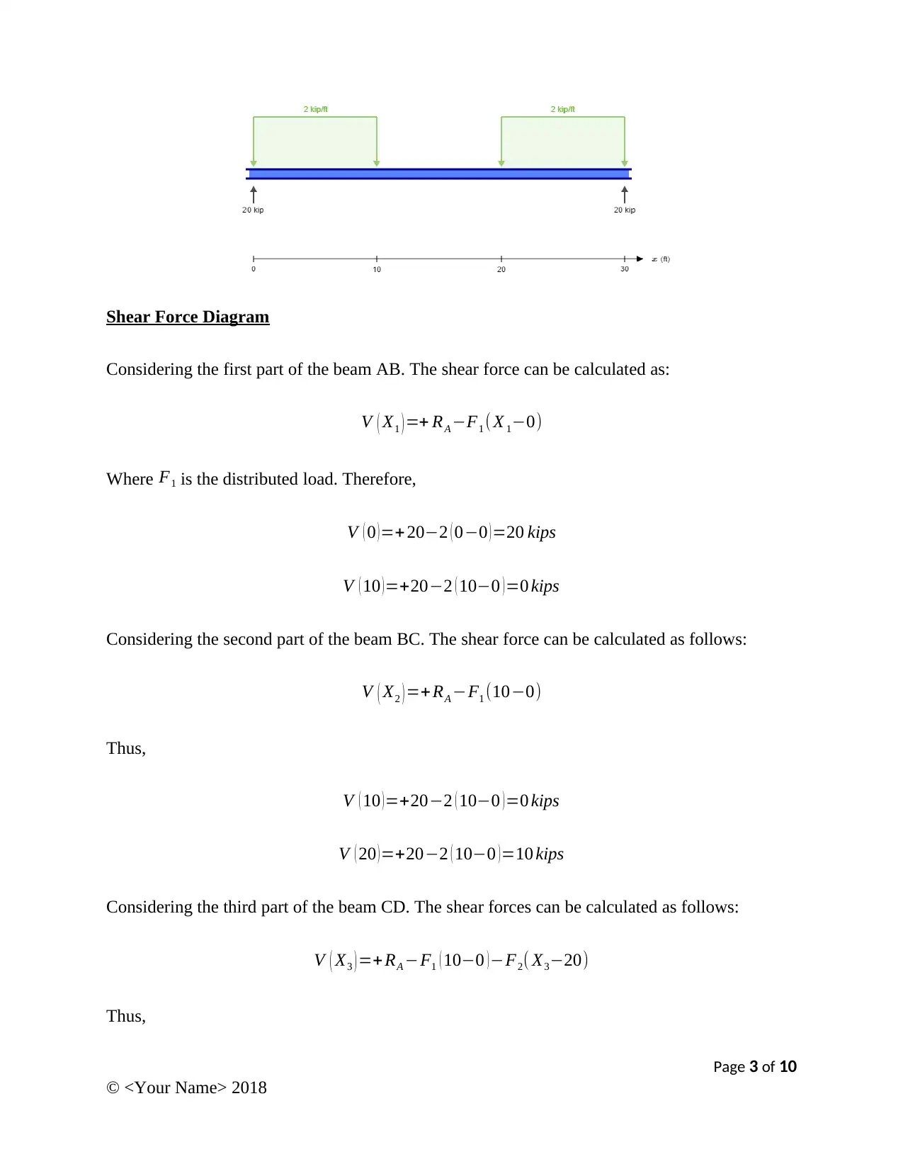
V ( 30 )=+20−2 ( 10−0 )−2 ( 30−20 )=−20 kips
With the above data, the shear force diagram is plotted as shown below:
Bending Moment Diagram
Considering the first part of the beam AB. The bending moments can be calculated as in the
equations below (Cleghorn and Dechev, 2016)
M ( X1 ) =+ R A ( X1 )−F1 ¿
Therefore,
M 1 ( 0 )=+20 ( 0 ) −2 ( ( 0−0 )2
2 )=0 kips−ft
M 1 ( 10 )=+20 ( 10 )−2 ( ( 10−0 )2
2 )=100 kips−ft
Considering the second part of the beam BC. The bending moments can be calculated as follows:
Page 4 of 10
© <Your Name> 2018
Paraphrase This Document
Need a fresh take? Get an instant paraphrase of this document with our AI Paraphraser
M ( X2 )=+ R A ( X2 ) −F1 (10−0)[ ( X2−10 ) + ( ( 10−0 )
2 )]
Therefore,
M 2 ( 10 ) =+20 ( 10 ) −2 ( 10 ) ( 0+5 ) =100 kip−ft
M 2 ( 20 ) =+20 ( 20 ) −2 ( 10 ) ( 10+5 ) =100 kip−ft
Considering the third part of the beam CD. The bending moments can be calculated as follows:
M ( X3 ) =+ R A ( X3 ) −F1 ( 10−0 ) [ ( X3−10 ) + ( ( 10−0 )
2 ) ] −F2 ( ( X3 −20 ) 2
2 )
Therefore,
M 3 ( 20 ) =+20 ( 20 ) −2 ( 10 ) ( 10+5 ) −2( ( 20−20 ) 2
2 )=100 kip−ft
M 3 ( 30 ) =+20 ( 30 ) −2 ( 10 ) ( 20+5 ) −2( ( 30−20 ) 2
2 )=0 kip−ft
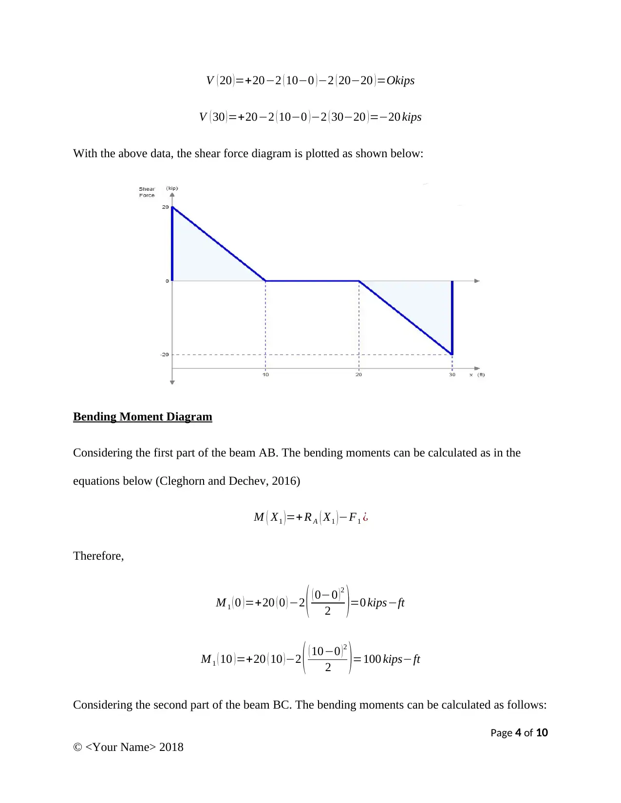
Using the values obtained above, the bending moment diagram can be plotted as below:
Page 5 of 10
© <Your Name> 2018
Question 2
Free Body Diagram
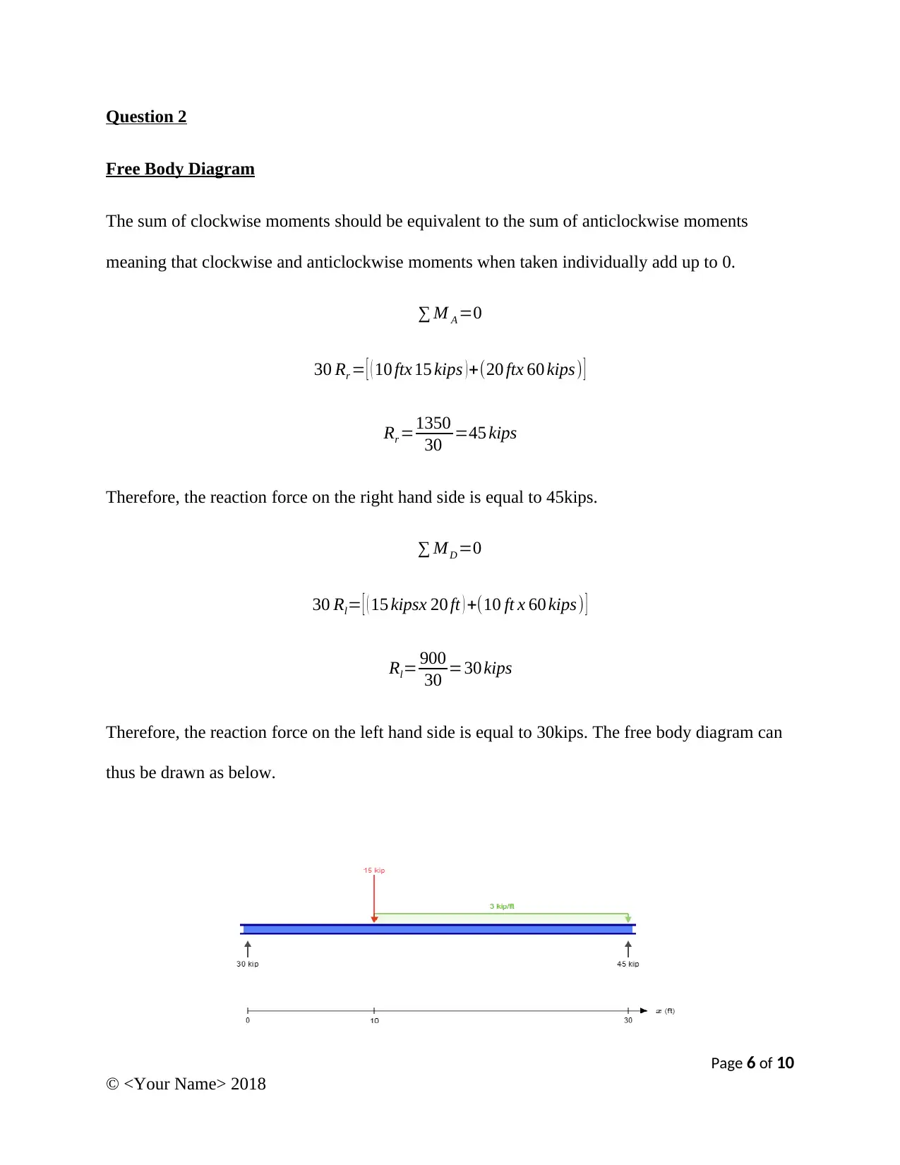
The sum of clockwise moments should be equivalent to the sum of anticlockwise moments
meaning that clockwise and anticlockwise moments when taken individually add up to 0.
∑ M A =0
30 Rr = [ ( 10 ftx 15 kips ) +(20 ftx 60 kips) ]
Rr =1350
30 =45 kips
Therefore, the reaction force on the right hand side is equal to 45kips.
∑ MD =0
30 Rl= [ ( 15 kipsx 20 ft ) +(10 ft x 60 kips) ]
Rl= 900
30 =30 kips
Therefore, the reaction force on the left hand side is equal to 30kips. The free body diagram can
thus be drawn as below.
Page 6 of 10
© <Your Name> 2018
⊘ This is a preview!⊘
Do you want full access?
Subscribe today to unlock all pages.

Trusted by 1+ million students worldwide
Shear Force Diagram
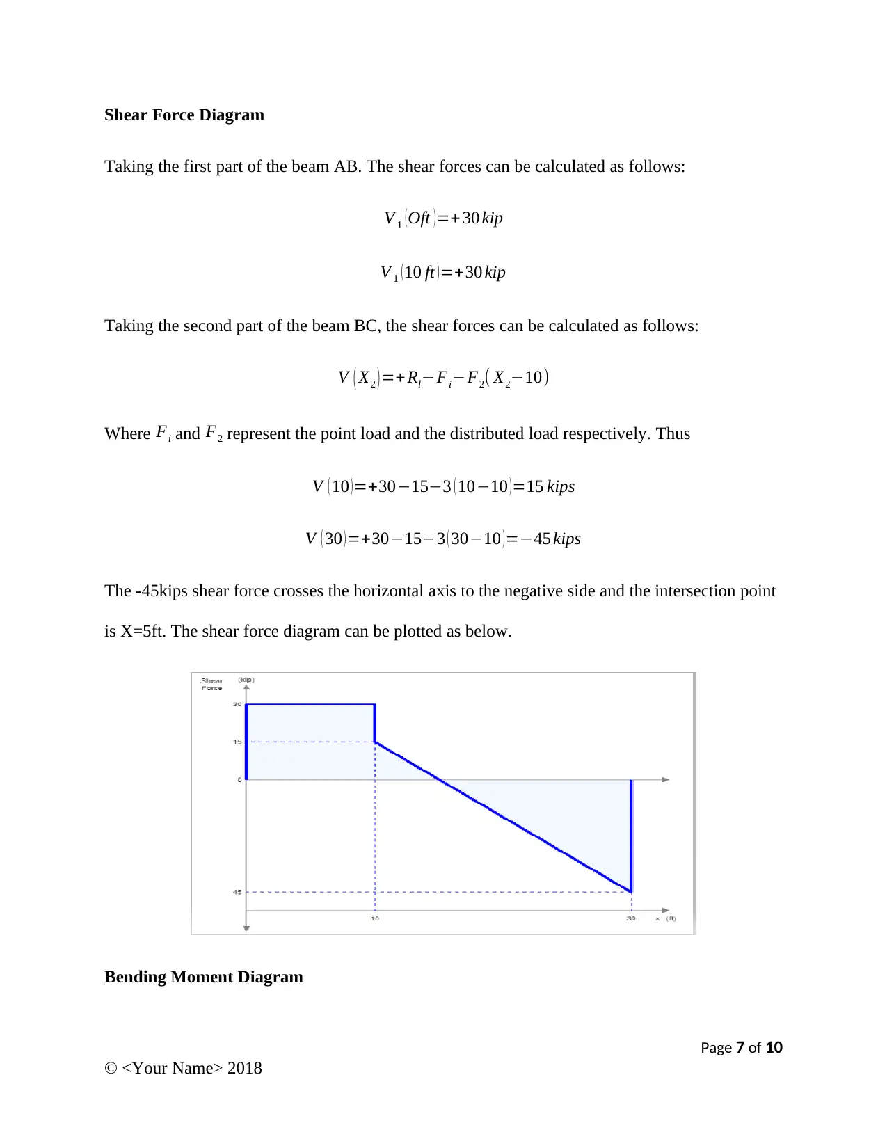
Taking the first part of the beam AB. The shear forces can be calculated as follows:
V 1 (Oft )=+ 30 kip
V 1 (10 ft )=+30 kip
Taking the second part of the beam BC, the shear forces can be calculated as follows:
V ( X2 ) =+ Rl−Fi−F2( X2−10)
Where Fi and F2 represent the point load and the distributed load respectively. Thus
V ( 10 ) =+30−15−3 ( 10−10 ) =15 kips
V ( 30 )=+30−15−3 ( 30−10 )=−45 kips
The -45kips shear force crosses the horizontal axis to the negative side and the intersection point
is X=5ft. The shear force diagram can be plotted as below.
Bending Moment Diagram
Page 7 of 10
© <Your Name> 2018
Paraphrase This Document
Need a fresh take? Get an instant paraphrase of this document with our AI Paraphraser
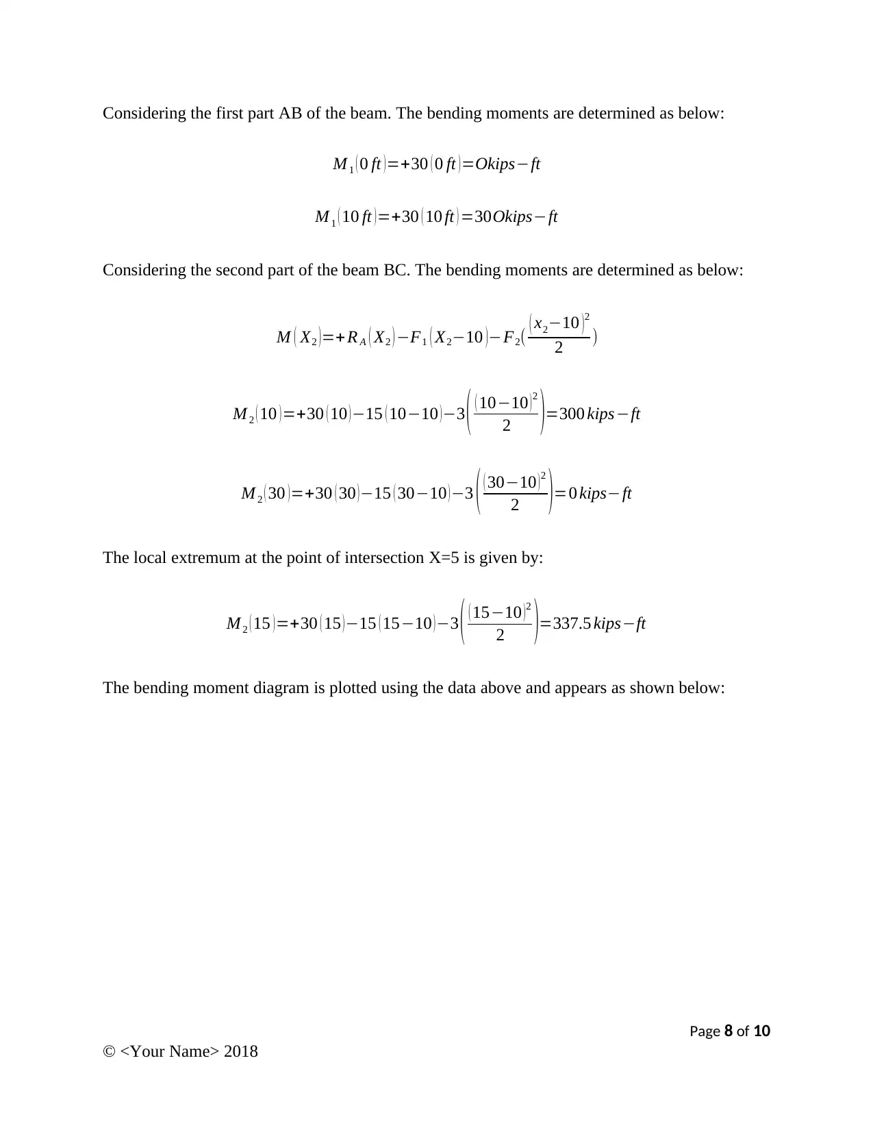
Considering the first part AB of the beam. The bending moments are determined as below:
M 1 ( 0 ft )=+30 ( 0 ft )=Okips−ft
M 1 ( 10 ft ) =+30 ( 10 ft ) =30Okips−ft
Considering the second part of the beam BC. The bending moments are determined as below:
M ( X2 )=+ R A ( X2 ) −F1 ( X2−10 )−F2( ( x2−10 )2
2 )
M 2 ( 10 )=+30 ( 10 )−15 ( 10−10 )−3 ( ( 10−10 )2
2 )=300 kips−ft
M 2 ( 30 ) =+30 ( 30 ) −15 ( 30−10 ) −3 ( ( 30−10 ) 2
2 )=0 kips−ft
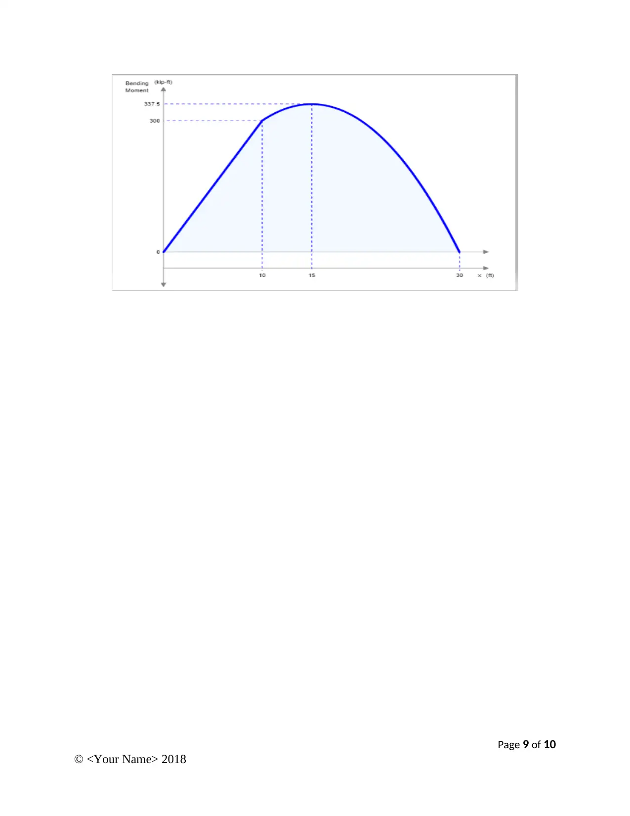
The local extremum at the point of intersection X=5 is given by:
M 2 ( 15 )=+30 ( 15 )−15 ( 15−10 )−3 ( ( 15−10 )2
2 )=337.5 kips−ft
The bending moment diagram is plotted using the data above and appears as shown below:
Page 8 of 10
© <Your Name> 2018
Page 9 of 10
© <Your Name> 2018
© <Your Name> 2018
⊘ This is a preview!⊘
Do you want full access?
Subscribe today to unlock all pages.

Trusted by 1+ million students worldwide
References
Cleghorn, W. L., and Dechev, N. 2016. Mechanics of machines. 2nd ed. Oxford: Oxford
University Press.
Ramamurti, V. 2011. Mechanics of machines. 3rd ed. New Delhi: Narosa Publishing House.
Page 10 of 10
© <Your Name> 2018
Cleghorn, W. L., and Dechev, N. 2016. Mechanics of machines. 2nd ed. Oxford: Oxford
University Press.
Ramamurti, V. 2011. Mechanics of machines. 3rd ed. New Delhi: Narosa Publishing House.
Page 10 of 10
© <Your Name> 2018
1 out of 10
Related Documents
Your All-in-One AI-Powered Toolkit for Academic Success.
+13062052269
info@desklib.com
Available 24*7 on WhatsApp / Email
![[object Object]](/_next/static/media/star-bottom.7253800d.svg)
Unlock your academic potential
Copyright © 2020–2025 A2Z Services. All Rights Reserved. Developed and managed by ZUCOL.


