Steam Turbine Power Plant: Layout, Circuits and Working
Added on 2023-05-29
20 Pages2097 Words311 Views
Steam Design Project

System Description:
A steam Turbine power plant is the system which is used for generating electrical energy from the
input heat energy. The gas turbines Power plants consist of four main circuits they are Ash and Coal
handling section, the Cooling water circuit, Air and Gas circuit and feed water and steam circuit’.1
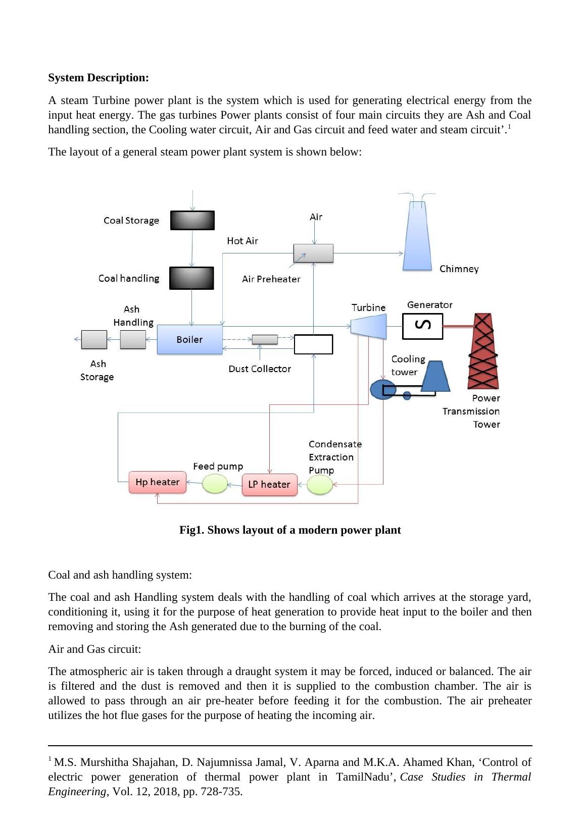
The layout of a general steam power plant system is shown below:
Fig1. Shows layout of a modern power plant
Coal and ash handling system:
The coal and ash Handling system deals with the handling of coal which arrives at the storage yard,
conditioning it, using it for the purpose of heat generation to provide heat input to the boiler and then
removing and storing the Ash generated due to the burning of the coal.
Air and Gas circuit:
The atmospheric air is taken through a draught system it may be forced, induced or balanced. The air
is filtered and the dust is removed and then it is supplied to the combustion chamber. The air is
allowed to pass through an air pre-heater before feeding it for the combustion. The air preheater
utilizes the hot flue gases for the purpose of heating the incoming air.
1 M.S. Murshitha Shajahan, D. Najumnissa Jamal, V. Aparna and M.K.A. Ahamed Khan, ‘Control of
electric power generation of thermal power plant in TamilNadu’, Case Studies in Thermal
Engineering, Vol. 12, 2018, pp. 728-735.
A steam Turbine power plant is the system which is used for generating electrical energy from the
input heat energy. The gas turbines Power plants consist of four main circuits they are Ash and Coal
handling section, the Cooling water circuit, Air and Gas circuit and feed water and steam circuit’.1
The layout of a general steam power plant system is shown below:
Fig1. Shows layout of a modern power plant
Coal and ash handling system:
The coal and ash Handling system deals with the handling of coal which arrives at the storage yard,
conditioning it, using it for the purpose of heat generation to provide heat input to the boiler and then
removing and storing the Ash generated due to the burning of the coal.
Air and Gas circuit:
The atmospheric air is taken through a draught system it may be forced, induced or balanced. The air
is filtered and the dust is removed and then it is supplied to the combustion chamber. The air is
allowed to pass through an air pre-heater before feeding it for the combustion. The air preheater
utilizes the hot flue gases for the purpose of heating the incoming air.
1 M.S. Murshitha Shajahan, D. Najumnissa Jamal, V. Aparna and M.K.A. Ahamed Khan, ‘Control of
electric power generation of thermal power plant in TamilNadu’, Case Studies in Thermal
Engineering, Vol. 12, 2018, pp. 728-735.
The air after completing the combustion becomes hot flue gas. The flue gas contains heat and some
quantity of ash. The flue gas is initially allowed to pass through the air preheater to exchange heat
with the inlet fresh air. Then the flue gas is passed through dust collectors in which most of the ash
and dust content of the flue air is removed. Then the flue air is allowed to exhaust to the atmosphere
via the chimney’.2
Feed water and Steam circuit:
The water follows a closed loop in this system. The condensed water from the condenser is allowed to
the boiler via economizer. The economizer uses the flue gases to preheat the feed water. The feed
water is then heated at the boiler the water is converted into steam. The generated steam is then
allowed to pass through the superheating boiler where the steam will be super-heated. Then the steam
is expanded in the Steam turbine. The expanded steam will have low velocity and low enthalpy. Then
the expanded steam is condensed in the condenser. There is always some form of water loss from the
circuit throughout the cycle so some fresh water is allowed inside the feed water pump to compensate
the loss’.2
Cooling water circuit:
The cooling water circuit consists of the water that is required to cool the steam flowing through the
condenser. The Water source is taken from large reservoirs such as lake, sea and rivers. The cooling
water may have an open loop circuit or closed loop circuit. In an open loop circuit the water taken
from the reservoir is allowed to flow out to the surrounding. In the case of a closed-loop system same
water is being circulated again and again inside the condenser the open loop system needs a separate
water cooling system such as an evaporative cooler’.4
General working:
The steam which is generated from the boiler is allowed to expand through the steam turbine which
in turn rotates the alternator. The conversion of the Mechanical energy into electrical energy is
achieved with the help of alternator. The steam turbine converts the steam energy into mechanical
energy. The steam-powered turbine works on the principle of baryon cycle.
2 M. K. Gupta and S. C. Kaushik, "Exergetic utilization of solar energy for feed water preheating in a
conventional thermal power plant", International Journal of Energy Research, Vol. 33, no. 6, 2009,
pp. 593-604.
4 A.N. Anozie and O.J. Odejobi, "The search for optimum condenser cooling water flow rate in a
thermal power plant", Applied Thermal Engineering, Vol. 31, no. 17-18, 2011, pp. 4083-4090.
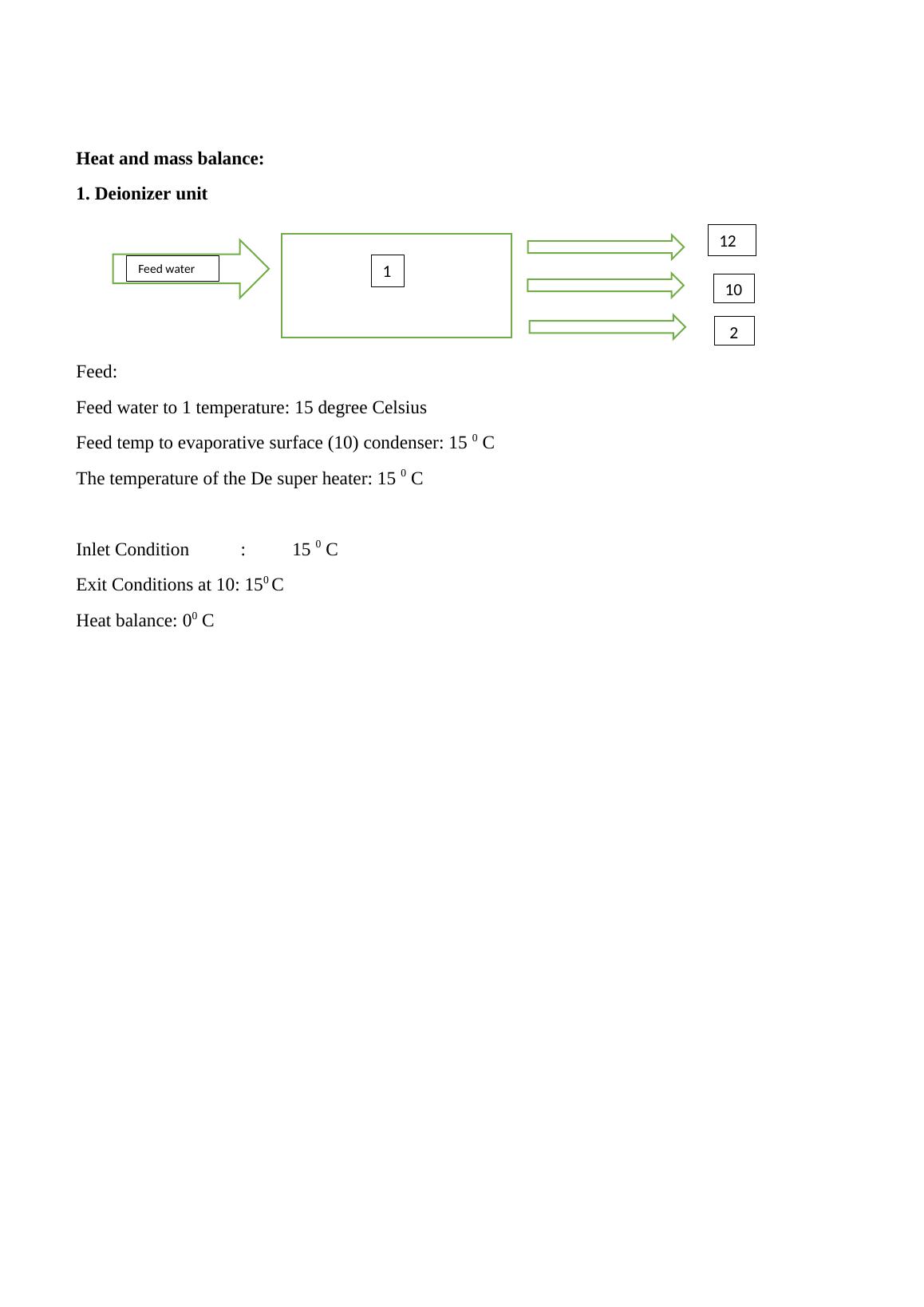
Heat and mass balance:
1. Deionizer unit
Feed:
Feed water to 1 temperature: 15 degree Celsius
Feed temp to evaporative surface (10) condenser: 15 0 C
The temperature of the De super heater: 15 0 C
Inlet Condition : 15 0 C
Exit Conditions at 10: 150 C
Heat balance: 00 C
12 12
10
2
Feed water 1
1. Deionizer unit
Feed:
Feed water to 1 temperature: 15 degree Celsius
Feed temp to evaporative surface (10) condenser: 15 0 C
The temperature of the De super heater: 15 0 C
Inlet Condition : 15 0 C
Exit Conditions at 10: 150 C
Heat balance: 00 C
12 12
10
2
Feed water 1
End of preview
Want to access all the pages? Upload your documents or become a member.
Related Documents
Engineering Research Method 2022lg...
|11
|1979
|17
Fly Ash Cement pva fibers Assignment PDFlg...
|9
|3059
|23
Improving Efficiency of Pressurized Boiler by Preheating Airlg...
|9
|1707
|352
Design Of Biomass Power Plant Report 2022lg...
|22
|3333
|46
Fundamentals of Thermodynamics and Heat Enginelg...
|8
|855
|68
Analysis of Organic Rankine Cyclelg...
|6
|2317
|424