EAT103 Lab Report: Stiffness of Materials & Moment of Inertia
VerifiedAdded on 2023/06/15
|10
|1615
|362
Report
AI Summary
This mechanical engineering lab report details experiments on the stiffness of materials and the moment of inertia of a flywheel. The stiffness experiment examines the deflection of aluminum, brass, and steel beams under load, comparing experimental and theoretical Young's moduli. Results indicate steel is the stiffest, followed by brass and aluminum. The moment of inertia experiment involves accelerating a flywheel with a falling mass, using Newtonian equations to determine its inertia. The report includes error analysis, discussing human errors and their impact on results. The linear relationship between material deflection and its nature is emphasized, with the Young's modulus serving as a key determinant of stiffness. Desklib provides access to similar reports and study resources for students.
UNIVERSITY AFFILIATION
DEPARTMENT OR FACULTY
MECHANICAL ENGINEERING
LAB REPORT
STUDENT NAME
STUDENT REGISTRATION NUMBER
&
GROUP MEMBERS
PROFESSOR (TUTOR)
DATE OF SUBMISSION
DEPARTMENT OR FACULTY
MECHANICAL ENGINEERING
LAB REPORT
STUDENT NAME
STUDENT REGISTRATION NUMBER
&
GROUP MEMBERS
PROFESSOR (TUTOR)
DATE OF SUBMISSION
Paraphrase This Document
Need a fresh take? Get an instant paraphrase of this document with our AI Paraphraser
ABSTRACT
This report aims at discussing the results obtained from the two experiments. The main findings of the lab
experiment were that the young modulus of the different materials differed despite using the same
measurements and load of materials. The theoretical values vary slightly from the experimental data. The
goal is the support structure is to be optimized for weight and stiffness or deflection. The deflection is
proportional to the load. The stiffness is the slope of the load-deflection curve. Stiffness is experienced in
tension and compression. The deflection in a cantilever beam with two supports on the bottom is
evaluated. The larger the area moment of inertia, the less a structure deflects or the more the stiffness
(Assets press Princeton). The area moment of inertia is an important parameter in determining the state of
stress in a part or component or structure. It is the resistance to buckling and the amount of deflection in a
beam. The area moment of inertia allows you to tell how stiff a structure is. The reference axis in the
beam is the centroidal axis. The deflection is set to be felt on the entire beam as the force is imparted at
the center. The elasticity module is a measure of material deformation under a load. A higher Value of E
implies that the structure deflects slightly (Youssefi and Anagnos).
Key words: Beam, Young’s Modulus, Moment of Inertia, stiffness, tension, compression, Newton law of
motion.
THEORY
Stiffness is a crucial property for many applications of materials. The stiffness of a structure depends on
both the properties of the material from which it is made and on the geometry of the structure. The
deflection of a simply supported beam,
The formula below applies to beams which are subjected to a central load acting at a right angle to their
length. The equation for the deflection of a beam supported between two points is given by:
∆= W L3
48 K
Where w is the load (N), Δ is deflection (m), L is the length (m), K is the flexural rigidity constant. K may
be calculated due to the second moment of area of the material, I, and the value of the Young’s Modulus
E.
K= E . I
Some of the theoretical standard values for materials:
Brass 105 Gpa
Aluminium 69 Gpa
Mild Steel 200 Gpa
The second moments of area (I) for solid and hollow beams is obtained as shown in the equation below.
For a solid beam of rectangular cross section:
I = b d3
12 [ m4 ]
LAB EXPERIMENT
EXPERIMENT 1: EAT103 – STIFFNESS OF MATERIALS
To achieve an understanding of the stiffness of different materials under load.
The apparatus ES4 uses an example of a very simple structure. It is comprised of a beam in three-point
bending. The apparatus explores beams of different material but identical dimensions and deflects by
different amounts for the same load, providing that their material property affects deflection. The
apparatus used is as illustrated below,
⊘ This is a preview!⊘
Do you want full access?
Subscribe today to unlock all pages.

Trusted by 1+ million students worldwide
Procedure
(i) Three beams of different material but of similar dimension were set up. The aluminum beam
weighed less than the other beams.
(ii) A dial caliper gauge was supplied with kid to accurately measure the beam dimensions. The
value of moment was computed and results recorded in a table.
(iii) The data was analyzed and plotted using excel where the gradient was obtained.
(iv) The same procedure was repeated for the other two beams
EXPERIMENT 2: EAT103- MOMENT OF
INERTIA OF A FLYWHEEL
To determine the moment of inertia of a
flywheel by accelerating it with a falling
mass.
Moment of inertia of a flywheel,
PROCEDURE:
1. The rate of descent for a particular mass
was measured as well as the
distance it fell.
Paraphrase This Document
Need a fresh take? Get an instant paraphrase of this document with our AI Paraphraser
2. The Newtonian equations were used to determine the moment of inertia of the flywheel by
plotting a graph.
3. Different masses were used for the different materials and the results were recorded in a
table.
RESULTS
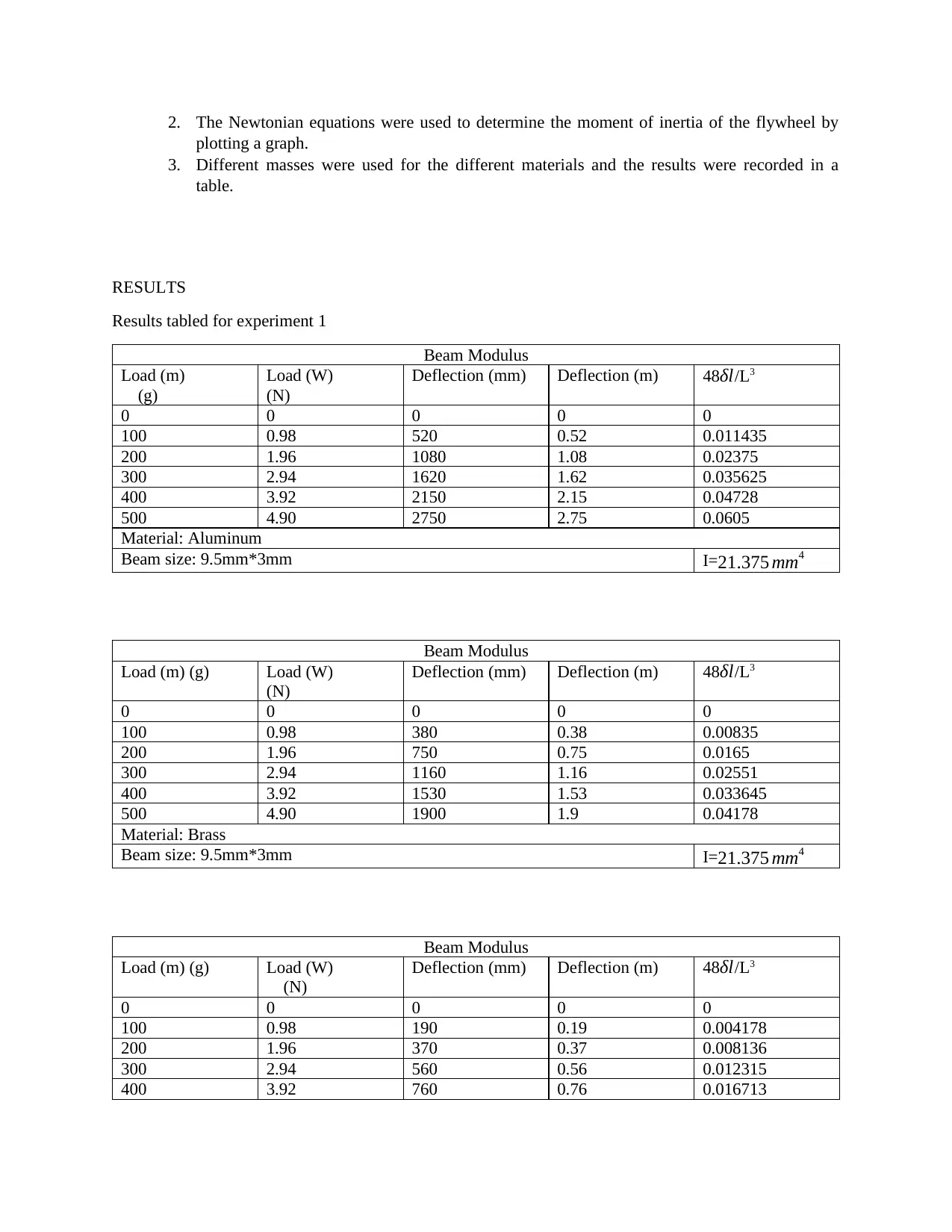
Results tabled for experiment 1
Beam Modulus
Load (m)
(g)
Load (W)
(N)
Deflection (mm) Deflection (m) 48δl/L3
0 0 0 0 0
100 0.98 520 0.52 0.011435
200 1.96 1080 1.08 0.02375
300 2.94 1620 1.62 0.035625
400 3.92 2150 2.15 0.04728
500 4.90 2750 2.75 0.0605
Material: Aluminum
Beam size: 9.5mm*3mm I=21.375 mm4
Beam Modulus
Load (m) (g) Load (W)
(N)
Deflection (mm) Deflection (m) 48δl/L3
0 0 0 0 0
100 0.98 380 0.38 0.00835
200 1.96 750 0.75 0.0165
300 2.94 1160 1.16 0.02551
400 3.92 1530 1.53 0.033645
500 4.90 1900 1.9 0.04178
Material: Brass
Beam size: 9.5mm*3mm I=21.375 mm4
Beam Modulus
Load (m) (g) Load (W)
(N)
Deflection (mm) Deflection (m) 48δl/L3
0 0 0 0 0
100 0.98 190 0.19 0.004178
200 1.96 370 0.37 0.008136
300 2.94 560 0.56 0.012315
400 3.92 760 0.76 0.016713
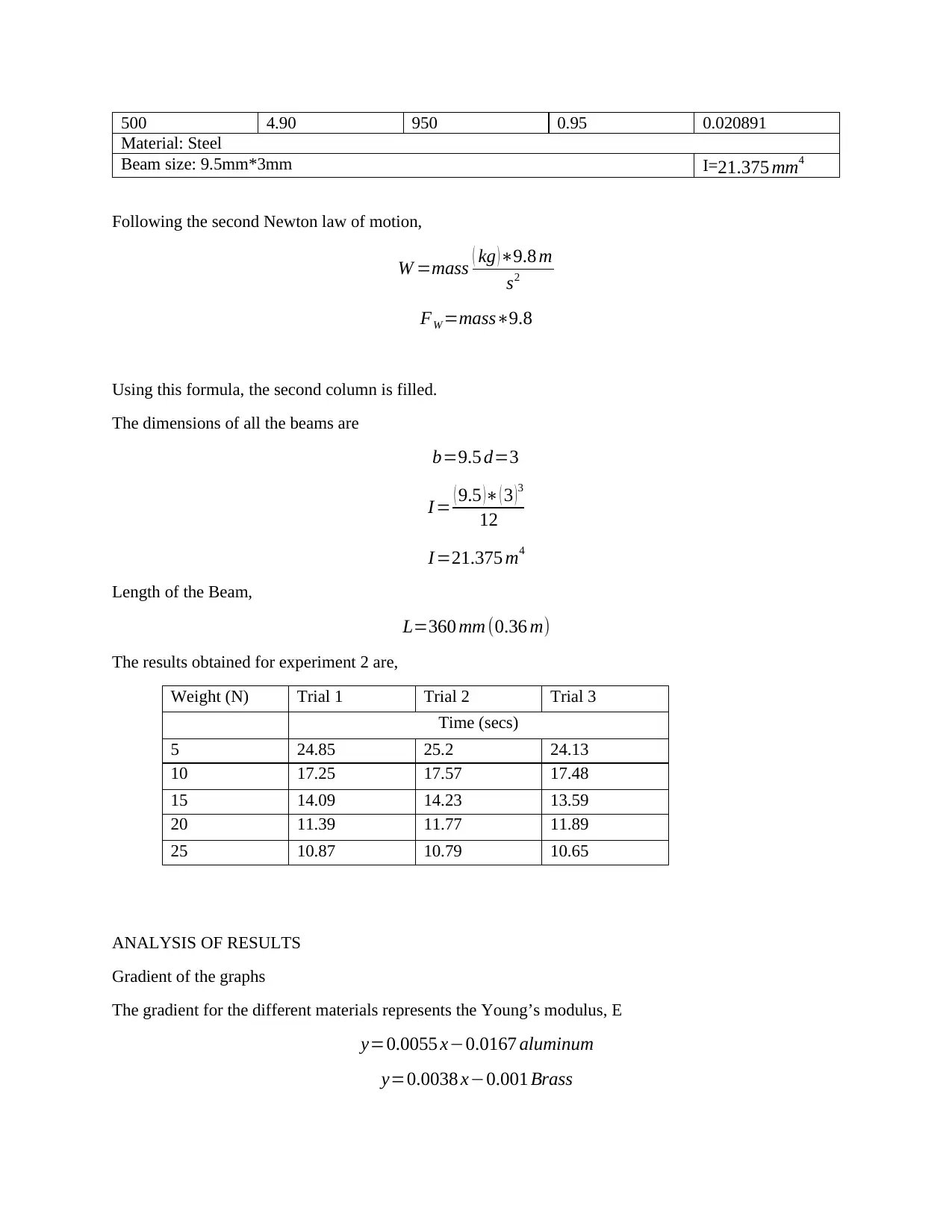
500 4.90 950 0.95 0.020891
Material: Steel
Beam size: 9.5mm*3mm I=21.375 mm4
Following the second Newton law of motion,
W =mass ( kg ) ∗9.8 m
s2
FW =mass∗9.8
Using this formula, the second column is filled.
The dimensions of all the beams are
b=9.5 d=3
I = ( 9.5 )∗ ( 3 )3
12
I =21.375 m4
Length of the Beam,
L=360 mm (0.36 m)
The results obtained for experiment 2 are,
Weight (N) Trial 1 Trial 2 Trial 3
Time (secs)
5 24.85 25.2 24.13
10 17.25 17.57 17.48
15 14.09 14.23 13.59
20 11.39 11.77 11.89
25 10.87 10.79 10.65
ANALYSIS OF RESULTS
Gradient of the graphs
The gradient for the different materials represents the Young’s modulus, E
y=0.0055 x−0.0167 aluminum
y=0.0038 x−0.001 Brass
⊘ This is a preview!⊘
Do you want full access?
Subscribe today to unlock all pages.

Trusted by 1+ million students worldwide
y=0.0019 x−0.0033 Steel
DISCUSSION
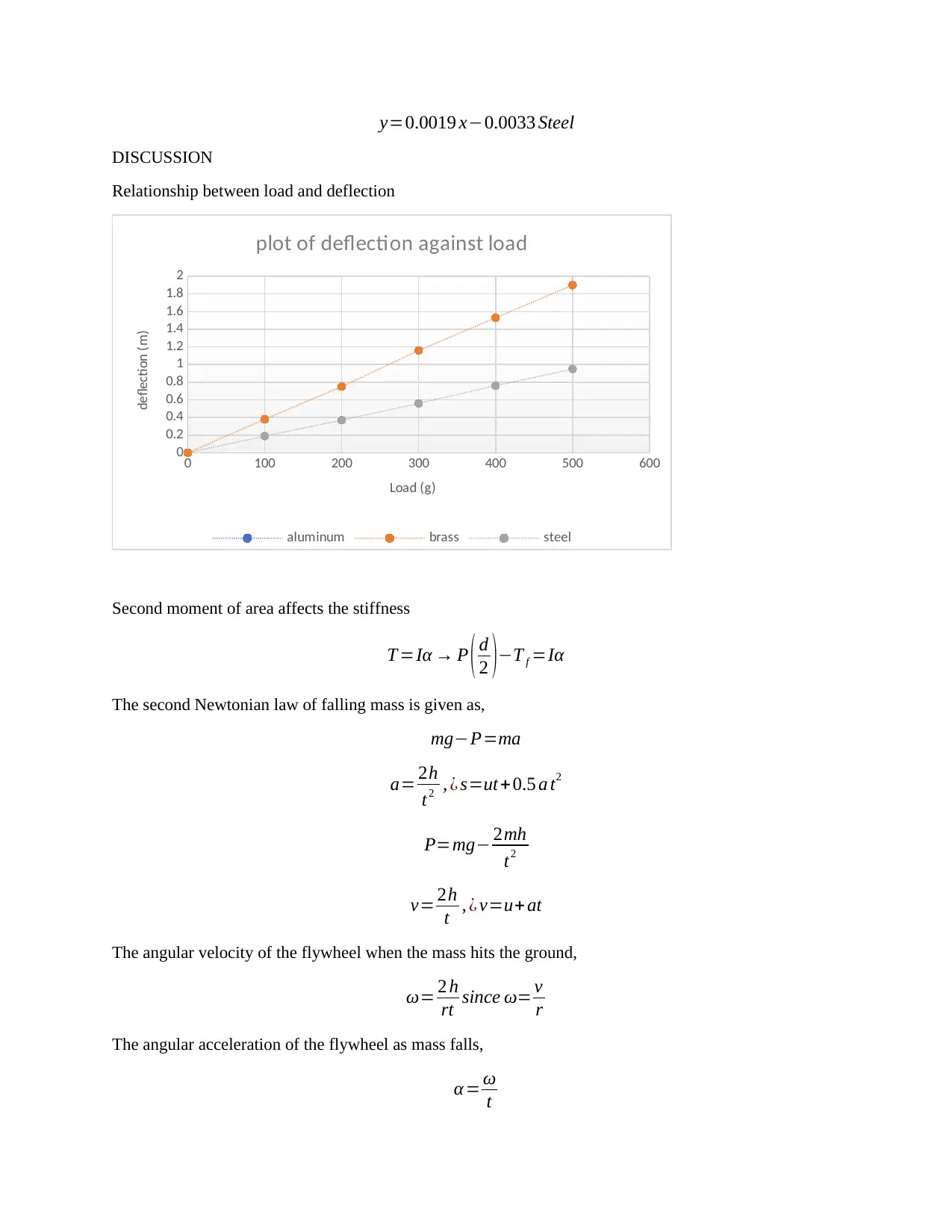
Relationship between load and deflection
0 100 200 300 400 500 600
0
0.2
0.4
0.6
0.8
1
1.2
1.4
1.6
1.8
2
plot of deflection against load
aluminum brass steel
Load (g)
deflection (m)
Second moment of area affects the stiffness
T =Iα → P ( d
2 )−T f =Iα
The second Newtonian law of falling mass is given as,
mg−P=ma
a= 2h
t2 , ¿ s=ut+ 0.5 a t2
P=mg− 2mh
t2
v= 2h
t , ¿ v=u+ at
The angular velocity of the flywheel when the mass hits the ground,
ω= 2 h
rt since ω= v
r
The angular acceleration of the flywheel as mass falls,
α = ω
t
Paraphrase This Document
Need a fresh take? Get an instant paraphrase of this document with our AI Paraphraser
α= 2h
t 2 r
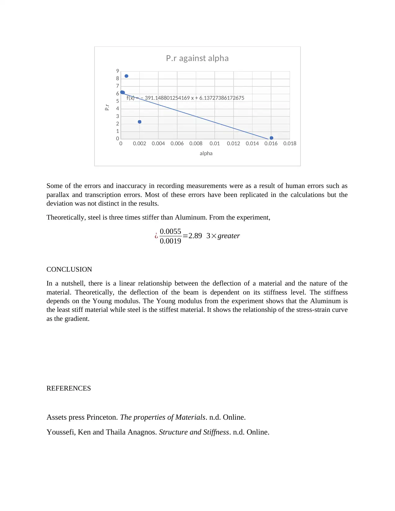
P . r=Iα+ T f
The equation is re-written in the linear equation format,
P . r=Iα+T f → y=mx+c
From the plot,
T f −isthe y−intercept
I =gradient of the plot →inertia of the flywheel
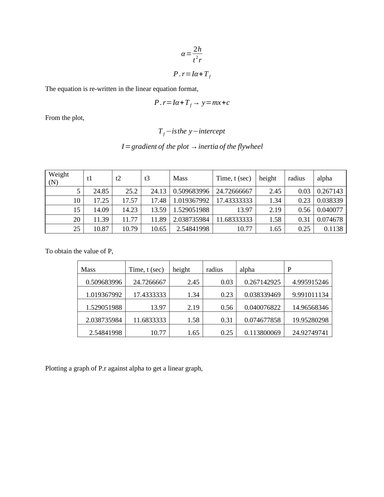
Weight
(N) t1 t2 t3 Mass Time, t (sec) height radius alpha
5 24.85 25.2 24.13 0.509683996 24.72666667 2.45 0.03 0.267143
10 17.25 17.57 17.48 1.019367992 17.43333333 1.34 0.23 0.038339
15 14.09 14.23 13.59 1.529051988 13.97 2.19 0.56 0.040077
20 11.39 11.77 11.89 2.038735984 11.68333333 1.58 0.31 0.074678
25 10.87 10.79 10.65 2.54841998 10.77 1.65 0.25 0.1138
To obtain the value of P,
Mass Time, t (sec) height radius alpha P
0.509683996 24.7266667 2.45 0.03 0.267142925 4.995915246
1.019367992 17.4333333 1.34 0.23 0.038339469 9.991011134
1.529051988 13.97 2.19 0.56 0.040076822 14.96568346
2.038735984 11.6833333 1.58 0.31 0.074677858 19.95280298
2.54841998 10.77 1.65 0.25 0.113800069 24.92749741
Plotting a graph of P.r against alpha to get a linear graph,
CONCLUSION
Some of the errors and inaccuracy in recording measurements were as a result of human errors such as
parallax and transcription errors. Most of these errors have been replicated in the calculations but the
deviation was not distinct in the results.
Theoretically, steel is three times stiffer than Aluminum. From the experiment,
¿ 0.0055
0.0019 =2.89 3×greater
CONCLUSION
In a nutshell, there is a linear relationship between the deflection of a material and the nature of the
material. Theoretically, the deflection of the beam is dependent on its stiffness level. The stiffness
depends on the Young modulus. The Young modulus from the experiment shows that the Aluminum is
the least stiff material while steel is the stiffest material. It shows the relationship of the stress-strain curve
as the gradient.
REFERENCES
Assets press Princeton. The properties of Materials. n.d. Online.
Youssefi, Ken and Thaila Anagnos. Structure and Stiffness. n.d. Online.
0 0.002 0.004 0.006 0.008 0.01 0.012 0.014 0.016 0.018
0
1
2
3
4
5
6
7
8
9
f(x) = − 391.148801254169 x + 6.13727386172675
P.r against alpha
alpha
P.r
⊘ This is a preview!⊘
Do you want full access?
Subscribe today to unlock all pages.

Trusted by 1+ million students worldwide

1 out of 10
Related Documents
Your All-in-One AI-Powered Toolkit for Academic Success.
+13062052269
info@desklib.com
Available 24*7 on WhatsApp / Email
![[object Object]](/_next/static/media/star-bottom.7253800d.svg)
Unlock your academic potential
Copyright © 2020–2025 A2Z Services. All Rights Reserved. Developed and managed by ZUCOL.


