Design of the mezzanine floor system for seasoned hard wood
VerifiedAdded on 2022/08/01
|13
|519
|213
AI Summary
just entering the data which is there in paper into word.
Contribute Materials
Your contribution can guide someone’s learning journey. Share your
documents today.
Structural Design
Design of timber structure
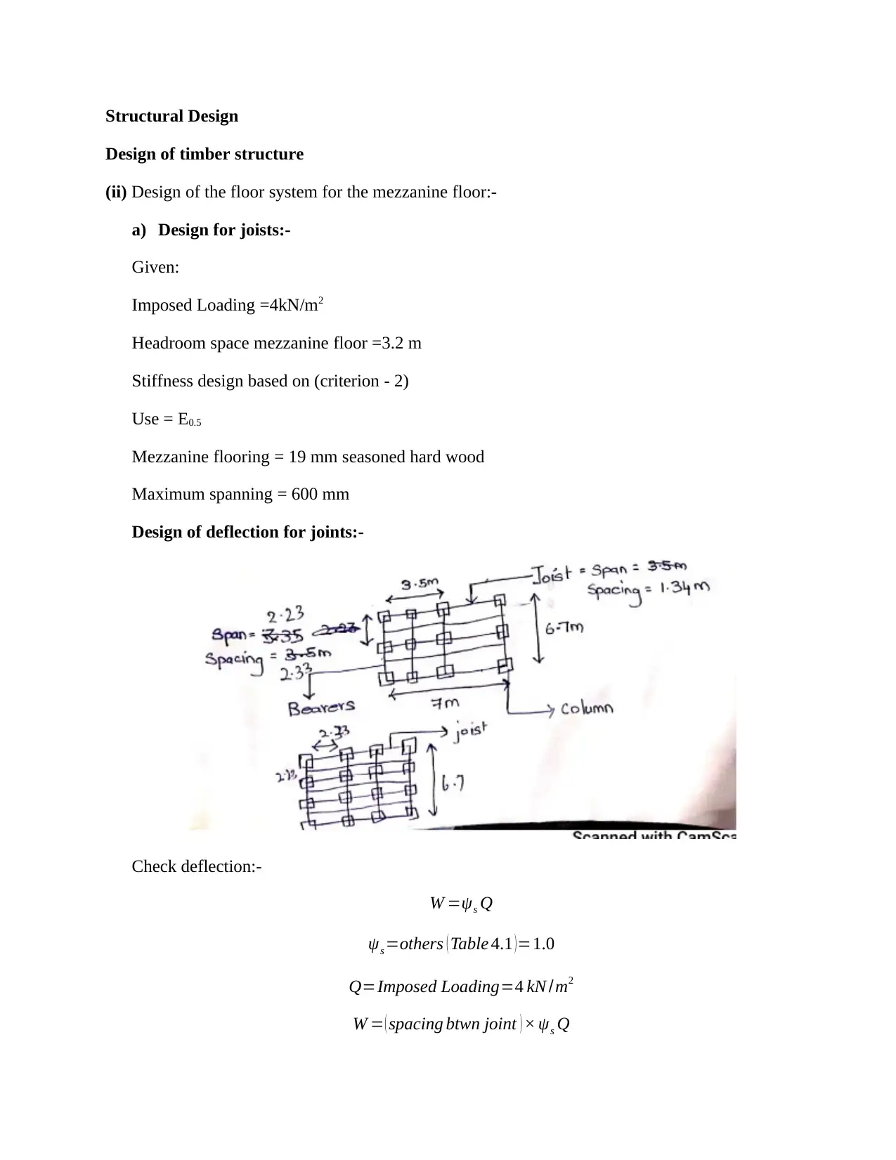
(ii) Design of the floor system for the mezzanine floor:-
a) Design for joists:-
Given:
Imposed Loading =4kN/m2
Headroom space mezzanine floor =3.2 m
Stiffness design based on (criterion - 2)
Use = E0.5
Mezzanine flooring = 19 mm seasoned hard wood
Maximum spanning = 600 mm
Design of deflection for joints:-
Check deflection:-
W =ψs Q
ψs =others ( Table 4.1 )=1.0
Q=Imposed Loading=4 kN /m2
W = ( spacing btwn joint ) × ψs Q
Design of timber structure
(ii) Design of the floor system for the mezzanine floor:-
a) Design for joists:-
Given:
Imposed Loading =4kN/m2
Headroom space mezzanine floor =3.2 m
Stiffness design based on (criterion - 2)
Use = E0.5
Mezzanine flooring = 19 mm seasoned hard wood
Maximum spanning = 600 mm
Design of deflection for joints:-
Check deflection:-
W =ψs Q
ψs =others ( Table 4.1 )=1.0
Q=Imposed Loading=4 kN /m2
W = ( spacing btwn joint ) × ψs Q
Secure Best Marks with AI Grader
Need help grading? Try our AI Grader for instant feedback on your assignments.
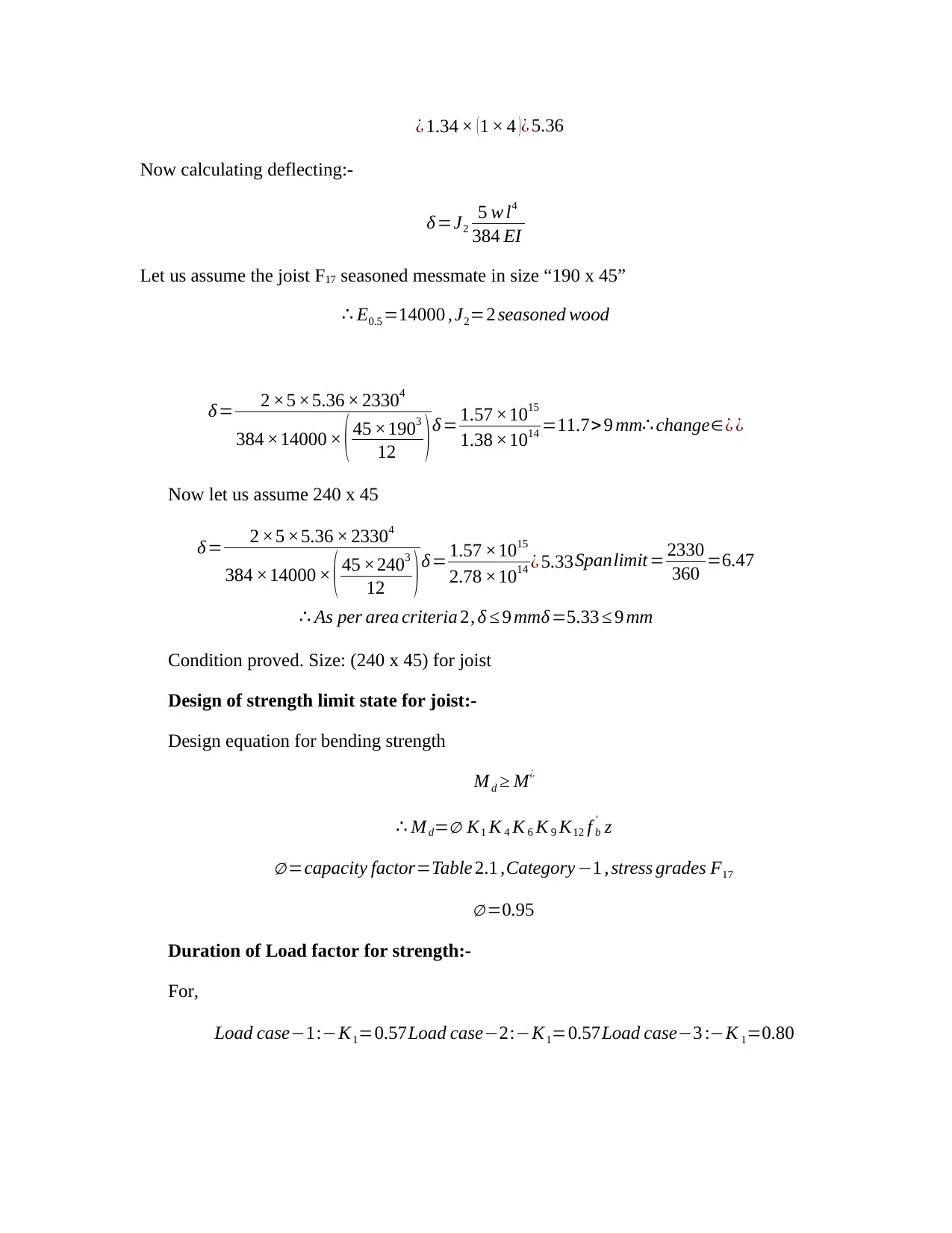
¿ 1.34 × (1 × 4 )¿ 5.36
Now calculating deflecting:-
δ =J2
5 w l4
384 EI
Let us assume the joist F17 seasoned messmate in size “190 x 45”
∴ E0.5 =14000 , J2=2 seasoned wood
δ = 2 ×5 ×5.36 × 23304
384 ×14000 × ( 45 ×1903
12 )δ = 1.57 ×10¹⁵
1.38 ×1014 =11.7>9 mm∴ change∈¿ ¿
Now let us assume 240 x 45
δ= 2 ×5 ×5.36 × 23304
384 ×14000 × ( 45 ×2403
12 ) δ = 1.57 ×10¹⁵
2.78 ×10¹⁴ ¿ 5.33Spanlimit = 2330
360 =6.47
∴ As per area criteria 2, δ ≤ 9 mmδ =5.33 ≤ 9 mm
Condition proved. Size: (240 x 45) for joist
Design of strength limit state for joist:-
Design equation for bending strength
M d ≥ M¿
∴ M d=∅ K1 K 4 K 6 K 9 K12 f b
' z
∅ =capacity factor=Table 2.1 ,Category −1 , stress grades F17
∅ =0.95
Duration of Load factor for strength:-
For,
Load case−1:−K1=0.57Load case−2:−K1=0.57 Load case−3 :−K 1=0.80
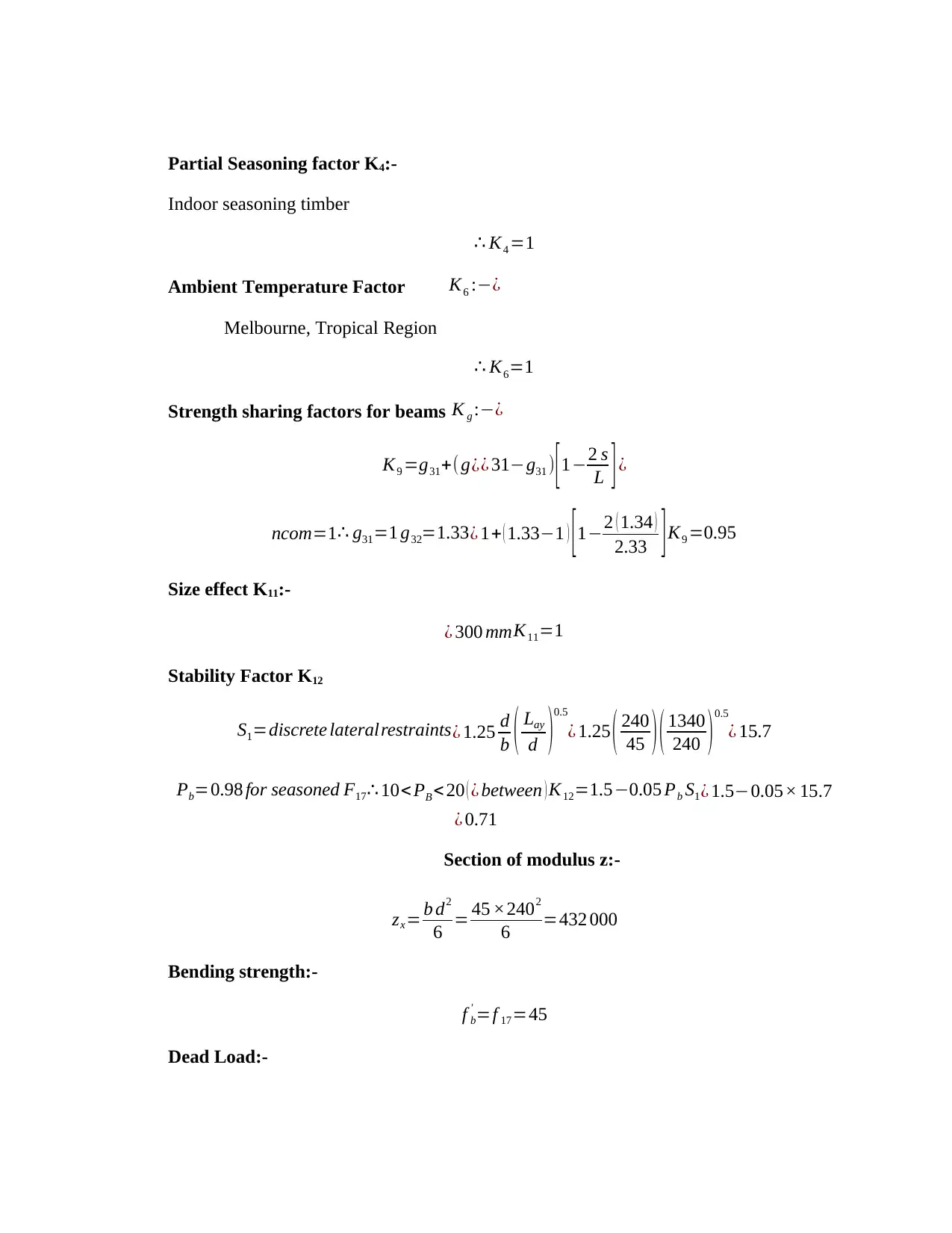
Partial Seasoning factor K4:-
Indoor seasoning timber
∴ K4 =1
Ambient Temperature Factor K6 :−¿
Melbourne, Tropical Region
∴ K6=1
Strength sharing factors for beams K g :−¿
K9 =g31+(g¿¿ 31−g31 ) [1−2 s
L ]¿
ncom=1∴ g31=1 g32=1.33¿ 1+ ( 1.33−1 ) [1−2 ( 1.34 )
2.33 ]K9 =0.95
Size effect K11:-
¿ 300 mm K11=1
Stability Factor K12
S1=discrete lateralrestraints¿ 1.25 d
b ( Lay
d )0.5
¿ 1.25 ( 240
45 )( 1340
240 ) 0.5
¿ 15.7
Pb=0.98 for seasoned F17∴ 10< PB < 20 ( ¿ between ) K12=1.5−0.05 Pb S1 ¿ 1.5−0.05× 15.7
¿ 0.71
Section of modulus z:-
zx= b d2
6 = 45 ×2402
6 =432 000
Bending strength:-
f b
' =f 17=45
Dead Load:-
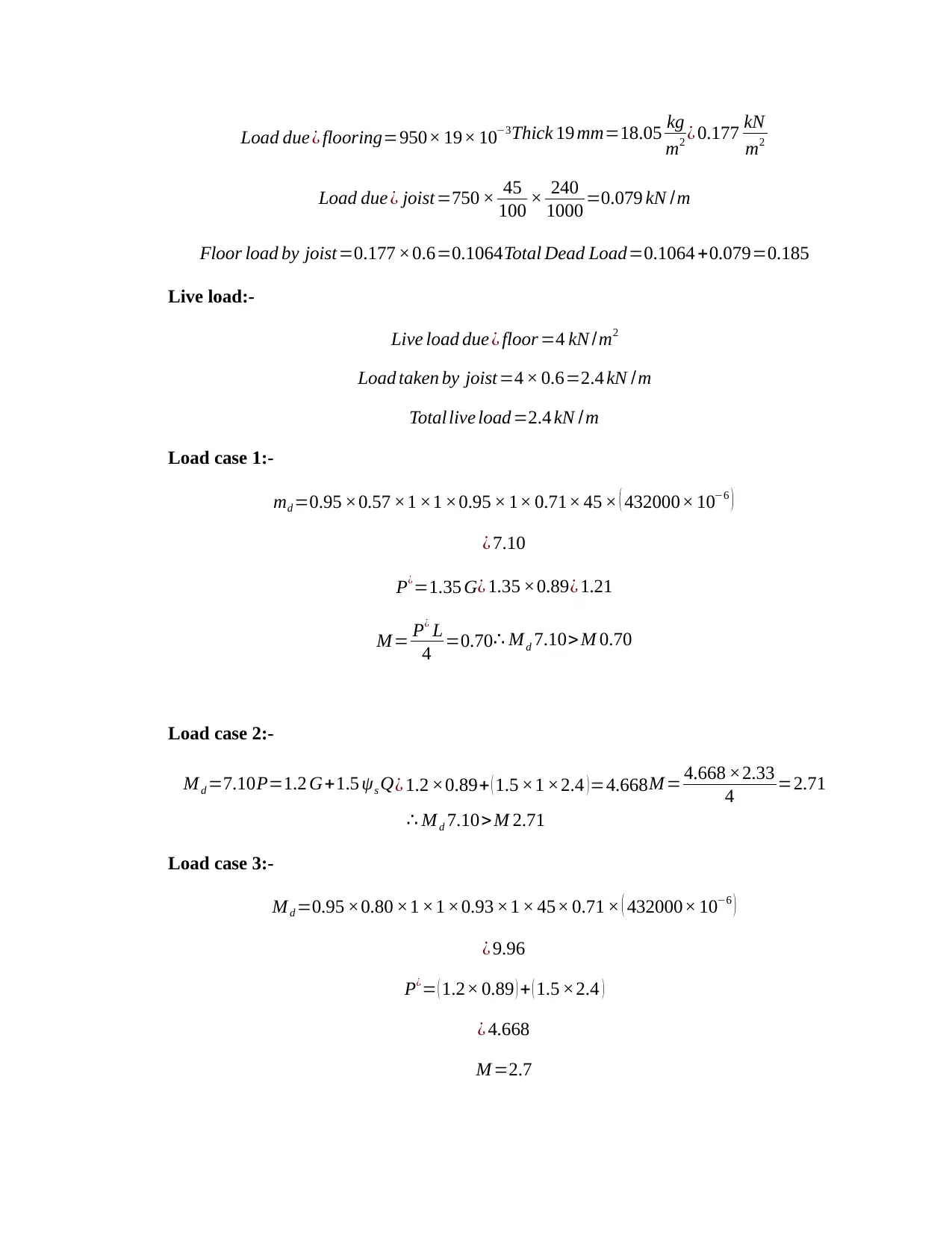
Load due ¿ flooring=950× 19× 10−3Thick 19 mm=18.05 kg
m2 ¿ 0.177 kN
m2
Load due ¿ joist=750 × 45
100 × 240
1000 =0.079 kN /m
Floor load by joist=0.177 ×0.6=0.1064Total Dead Load=0.1064 +0.079=0.185
Live load:-
Live load due ¿ floor =4 kN /m2
Load taken by joist=4 × 0.6=2.4 kN /m
Total live load=2.4 kN / m
Load case 1:-
md =0.95 ×0.57 ×1 ×1 ×0.95 × 1× 0.71× 45 × ( 432000× 10−6 )
¿ 7.10
P¿=1.35 G¿ 1.35 ×0.89 ¿ 1.21
M= P¿ L
4 =0.70 ∴ Md 7.10> M 0.70
Load case 2:-
M d =7.10 P=1.2 G+1.5 ψs Q ¿ 1.2 ×0.89+ ( 1.5 ×1 ×2.4 ) =4.668M = 4.668 ×2.33
4 =2.71
∴ M d 7.10> M 2.71
Load case 3:-
M d =0.95 ×0.80 ×1 ×1 ×0.93 ×1 × 45× 0.71 × ( 432000× 10−6 )
¿ 9.96
P¿= ( 1.2× 0.89 ) + ( 1.5 ×2.4 )
¿ 4.668
M =2.7
Secure Best Marks with AI Grader
Need help grading? Try our AI Grader for instant feedback on your assignments.
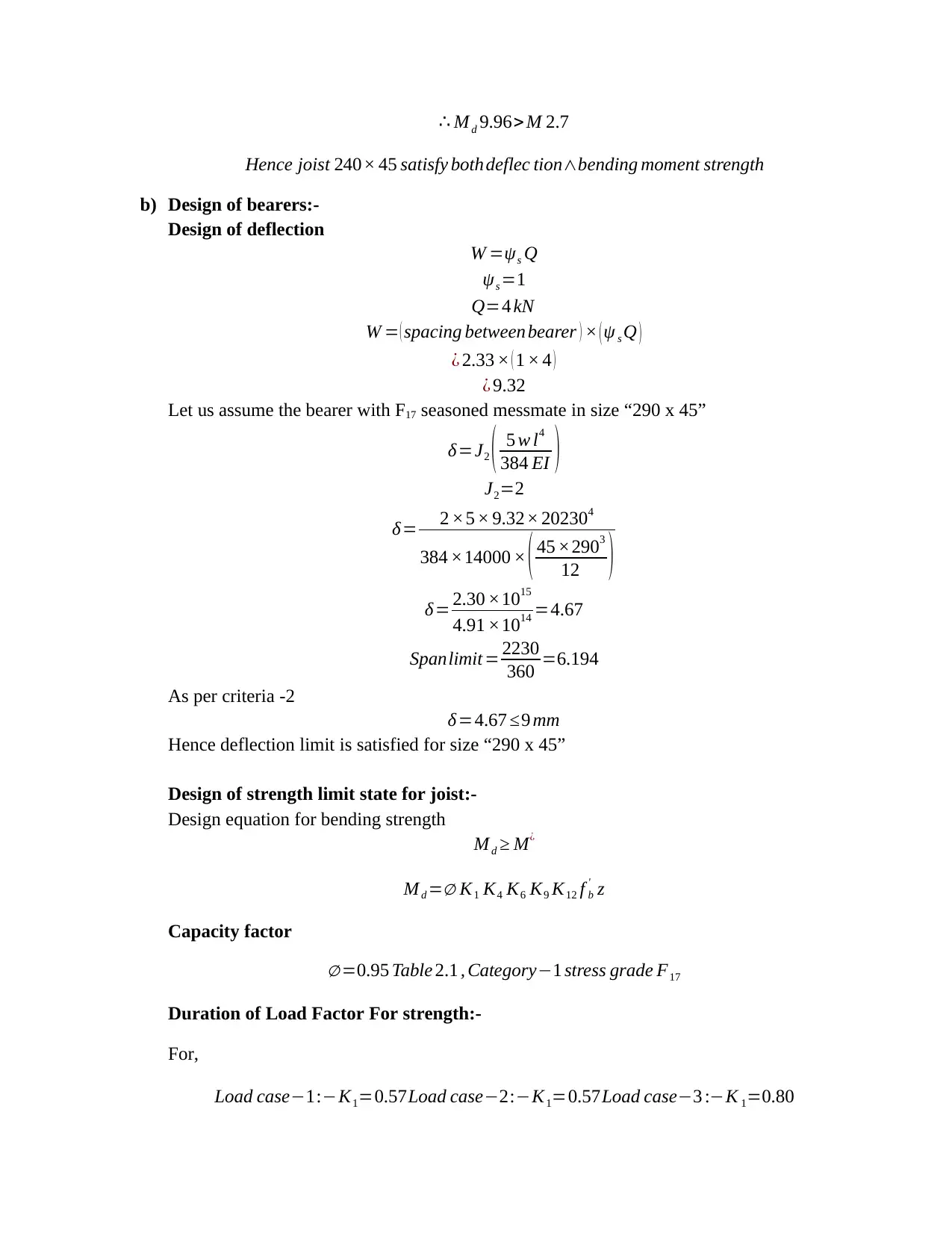
∴ M d 9.96> M 2.7
Hence joist 240× 45 satisfy bothdeflec tion∧bending moment strength
b) Design of bearers:-
Design of deflection
W =ψs Q
ψs =1
Q=4 kN
W = ( spacing between bearer ) × ( ψ s Q )
¿ 2.33 × ( 1 × 4 )
¿ 9.32
Let us assume the bearer with F17 seasoned messmate in size “290 x 45”
δ=J2 ( 5 w l4
384 EI )
J2=2
δ= 2 ×5 × 9.32× 202304
384 ×14000 × ( 45 ×2903
12 )
δ = 2.30 ×10¹⁵
4.91 ×1014 =4.67
Spanlimit = 2230
360 =6.194
As per criteria -2
δ=4.67 ≤9 mm
Hence deflection limit is satisfied for size “290 x 45”
Design of strength limit state for joist:-
Design equation for bending strength
M d ≥ M¿
M d =∅ K1 K4 K6 K9 K12 f b
' z
Capacity factor
∅ =0.95 Table 2.1 , Category−1 stress grade F17
Duration of Load Factor For strength:-
For,
Load case−1:−K1=0.57Load case−2:−K1=0.57 Load case−3 :−K 1=0.80
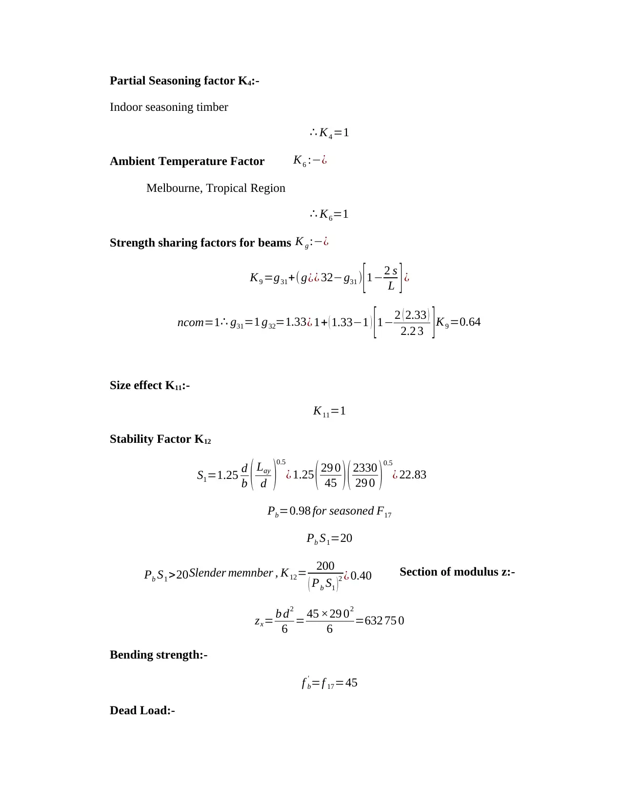
Partial Seasoning factor K4:-
Indoor seasoning timber
∴ K4 =1
Ambient Temperature Factor K6 :−¿
Melbourne, Tropical Region
∴ K6=1
Strength sharing factors for beams K g :−¿
K9 =g31+(g¿¿ 32−g31 ) [ 1−2 s
L ] ¿
ncom=1 ∴ g31=1 g32=1.33¿ 1+ ( 1.33−1 ) [1−2 ( 2.33 )
2.2 3 ] K9 =0.64
Size effect K11:-
K11=1
Stability Factor K12
S1=1.25 d
b ( Lay
d )
0.5
¿ 1.25 ( 29 0
45 )( 2330
29 0 )0.5
¿ 22.83
Pb=0.98 for seasoned F17
Pb S1=20
Pb S1 >20 Slender memnber , K12= 200
( Pb S1 ) 2 ¿ 0.40 Section of modulus z:-
zx= b d2
6 = 45 ×29 02
6 =632 75 0
Bending strength:-
f b
' =f 17=45
Dead Load:-
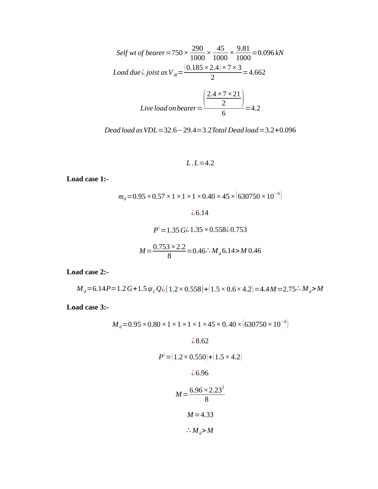
Self wt of bearer=750 × 290
1000 × 45
1000 × 9.81
1000 =0.096 kN
Load due ¿ joist as V dl= ( 0.185 ×2.4 ) × 7× 3
2 =4.662
Live load on bearer= ( 2.4 ×7 ×21
2 )
6 =4.2
Dead load as VDL=32.6−29.4=3.2 Total Dead load=3.2+0.096
L . L=4.2
Load case 1:-
md =0.95 ×0.57 ×1 ×1 ×1 ×0.40 × 45 × ( 630750 ×10−6 )
¿ 6.14
P¿=1.35 G¿ 1.35 ×0.558¿ 0.753
M = 0.753 ×2.2
8 =0.46 ∴ Md 6.14> M 0.46
Load case 2:-
M d =6.14 P=1.2 G+1.5 ψL Q¿( 1.2× 0.558)+ ( 1.5 × 0.6× 4.2 ) =4.4 M =2.75 ∴ M d > M
Load case 3:-
M d =0.95 ×0.80 ×1 ×1 ×1 ×1 ×45 × 0. 40 × ( 630750 ×10−6 )
¿ 8.62
P¿= ( 1.2× 0.550 ) + ( 1.5 × 4.2 )
¿ 6.96
M = 6.96 ×2.232
8
M =4.33
∴ Md > M
Paraphrase This Document
Need a fresh take? Get an instant paraphrase of this document with our AI Paraphraser
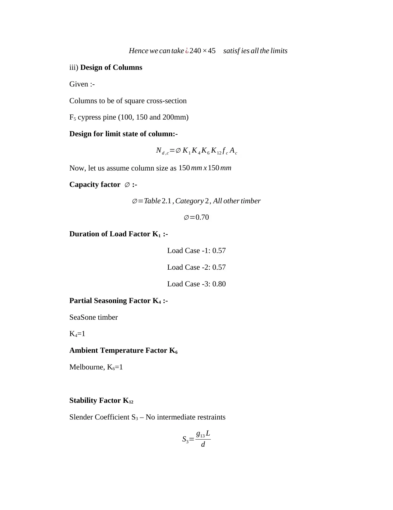
Hence we can take ¿ 240 ×45 satisf ies all the limits
iii) Design of Columns
Given :-
Columns to be of square cross-section
F5 cypress pine (100, 150 and 200mm)
Design for limit state of column:-
Nd ,c=∅ K1 K 4 K6 K12 f c Ac
Now, let us assume column size as 150 mm x 150 mm
Capacity factor ∅ :-
∅ =Table 2.1 , Category 2, All other timber
∅ =0.70
Duration of Load Factor K1 :-
Load Case -1: 0.57
Load Case -2: 0.57
Load Case -3: 0.80
Partial Seasoning Factor K4 :-
SeaSone timber
K4=1
Ambient Temperature Factor K6
Melbourne, K6=1
Stability Factor K12
Slender Coefficient S3 – No intermediate restraints
S3= g13 L
d
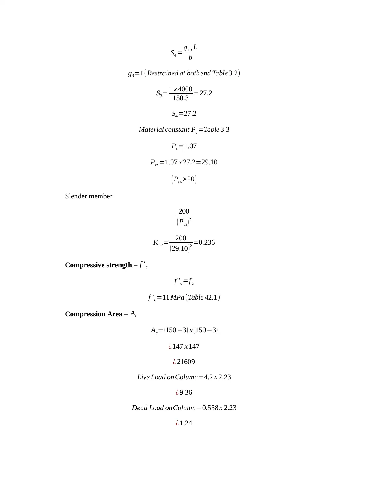
S4 = g13 L
b
g3=1( Restrained at both end Table 3.2)
S3= 1 x 4000
150.3 =27.2
S4 =27.2
Material constant Pc=Table 3.3
Pc=1.07
Pcs =1.07 x 27.2=29.10
( Pcs > 20 )
Slender member
200
( Pcs )2
K12= 200
( 29.10 ) 2 =0.236
Compressive strength – f 'c
f ' c=f s
f 'c=11 MPa (Table 42.1)
Compression Area – Ac
Ac= (150−3 ) x ( 150−3 )
¿ 147 x 147
¿ 21609
Live Load on Column=4.2 x 2.23
¿ 9.36
Dead Load onColumn=0.558 x 2.23
¿ 1.24
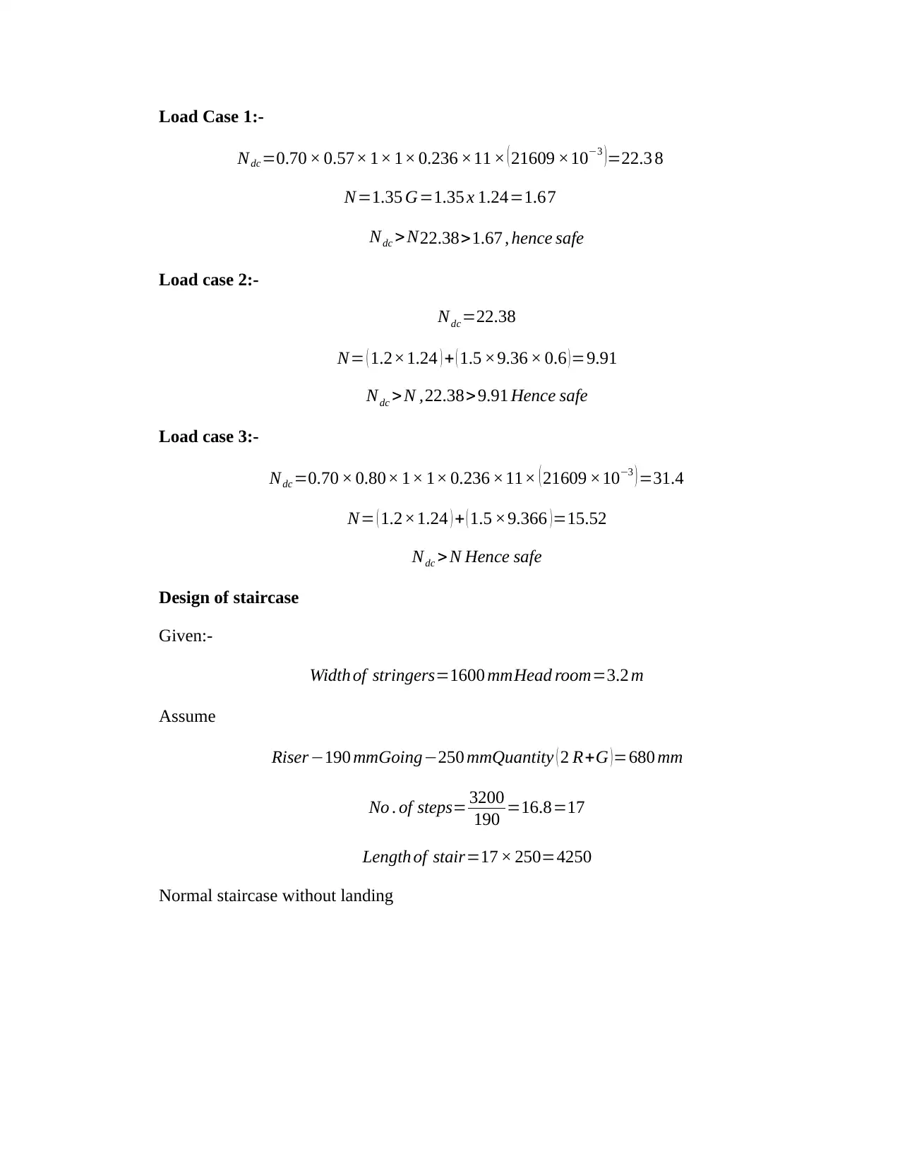
Load Case 1:-
Ndc=0.70 × 0.57× 1× 1× 0.236 ×11 × ( 21609 ×10−3 )=22.3 8
N=1.35 G=1.35 x 1.24=1.67
Ndc >N22.38>1.67 , hence safe
Load case 2:-
Ndc=22.38
N= ( 1.2×1.24 ) + ( 1.5 ×9.36 × 0.6 )=9.91
Ndc >N ,22.38> 9.91 Hence safe
Load case 3:-
Ndc =0.70 × 0.80× 1× 1× 0.236 ×11× ( 21609 ×10−3 ) =31.4
N= ( 1.2×1.24 ) + ( 1.5 ×9.366 ) =15.52
Ndc > N Hence safe
Design of staircase
Given:-
Width of stringers=1600 mmHead room=3.2 m
Assume
Riser−190 mm Going−250 mmQuantity ( 2 R+G )=680 mm
No . of steps= 3200
190 =16.8=17
Length of stair=17 × 250=4250
Normal staircase without landing
Secure Best Marks with AI Grader
Need help grading? Try our AI Grader for instant feedback on your assignments.
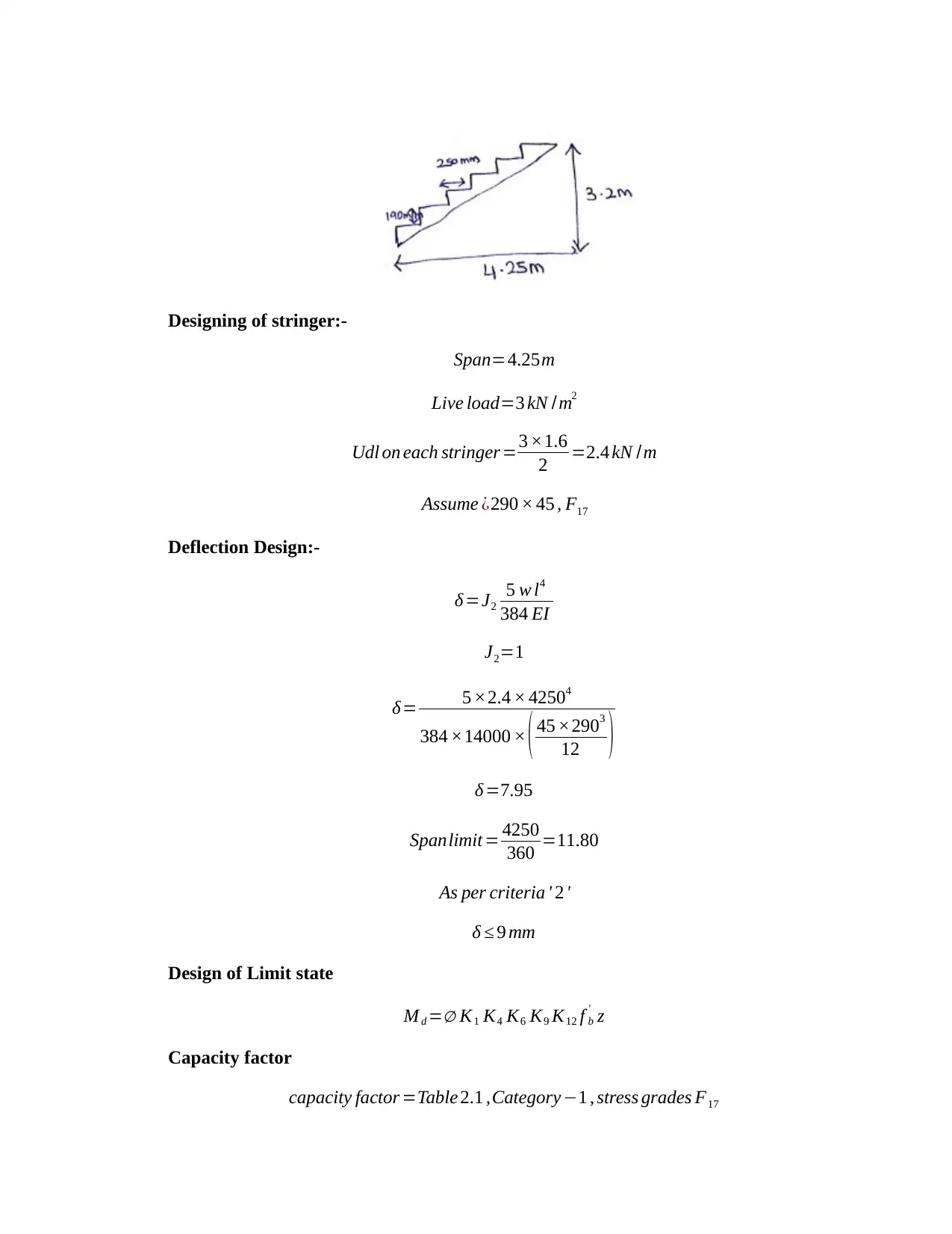
Designing of stringer:-
Span=4.25m
Live load=3 kN /m2
Udl on each stringer=3 ×1.6
2 =2.4 kN /m
Assume ¿290 × 45 , F17
Deflection Design:-
δ =J2
5 w l4
384 EI
J2=1
δ= 5 ×2.4 × 42504
384 ×14000 × ( 45 ×2903
12 )
δ =7.95
Spanlimit = 4250
360 =11.80
As per criteria ' 2 '
δ ≤ 9 mm
Design of Limit state
M d =∅ K1 K4 K6 K9 K12 f b
' z
Capacity factor
capacity factor =Table 2.1 ,Category −1 , stress grades F17
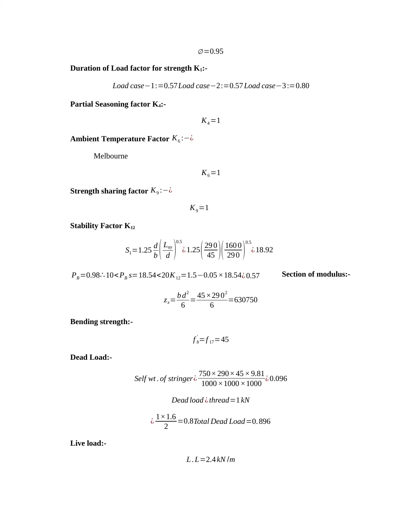
∅ =0.95
Duration of Load factor for strength K1:-
Load case−1:=0.57Load case−2:=0.57 Load case−3 :=0.80
Partial Seasoning factor K4:-
K4 =1
Ambient Temperature Factor K6 :−¿
Melbourne
K6 =1
Strength sharing factor K9 :−¿
K9 =1
Stability Factor K12
S1=1.25 d
b ( Lay
d )
0.5
¿ 1.25 ( 29 0
45 )( 160 0
29 0 )0.5
¿ 18.92
PB =0.98∴ 10< PB s=18.54<20K12=1.5−0.05 ×18.54 ¿ 0.57 Section of modulus:-
zx= b d2
6 = 45 ×29 02
6 =630750
Bending strength:-
f b
' =f 17=45
Dead Load:-
Self wt . of stringer¿ 750× 290× 45 × 9.81
1000 ×1000 ×1000 ¿ 0.096
Dead load ¿ thread=1 kN
¿ 1×1.6
2 =0.8Total Dead Load=0. 896
Live load:-
L . L=2.4 kN /m
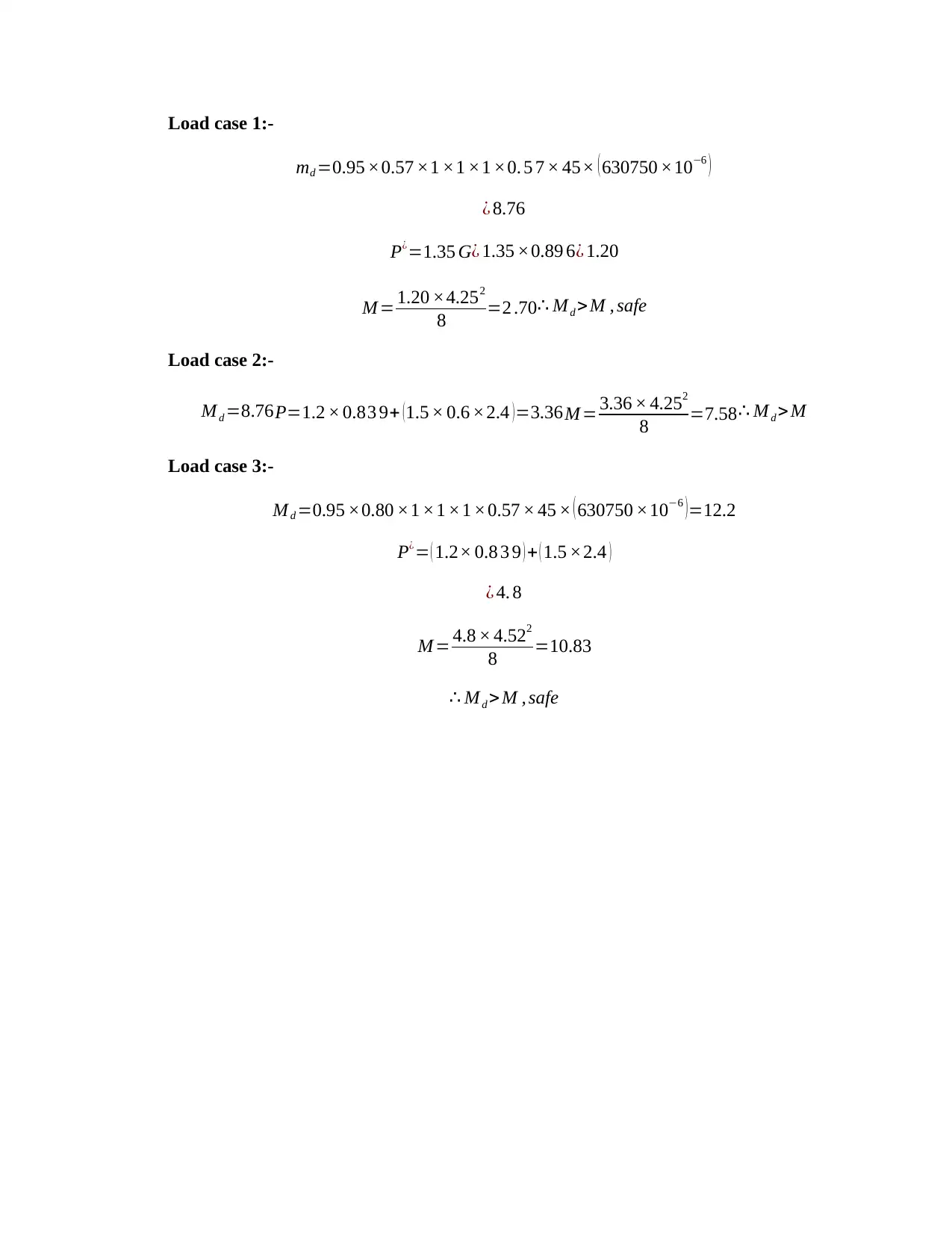
Load case 1:-
md =0.95 ×0.57 ×1 ×1 ×1 ×0. 5 7 × 45× ( 630750 ×10−6 )
¿ 8.76
P¿=1.35 G¿ 1.35 ×0.89 6¿ 1.20
M = 1.20 ×4.252
8 =2 .70 ∴ Md >M , safe
Load case 2:-
M d =8.76P=1.2 × 0.83 9+ (1.5 × 0.6 ×2.4 )=3.36M = 3.36 × 4.252
8 =7.58 ∴ M d > M
Load case 3:-
M d =0.95 ×0.80 ×1 ×1 ×1 ×0.57 × 45 × ( 630750 ×10−6 ) =12.2
P¿= ( 1.2× 0.8 3 9 ) + ( 1.5 ×2.4 )
¿ 4. 8
M = 4.8 × 4.522
8 =10.83
∴ M d > M , safe
1 out of 13

Your All-in-One AI-Powered Toolkit for Academic Success.
+13062052269
info@desklib.com
Available 24*7 on WhatsApp / Email
![[object Object]](/_next/static/media/star-bottom.7253800d.svg)
Unlock your academic potential
© 2024 | Zucol Services PVT LTD | All rights reserved.